

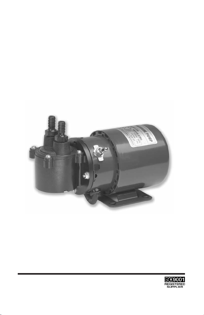
OPERATING MANUAL
AIR CADET®PUMPS
MODEL NO. 420-1901
MODEL NO. 420-1902
A-1299-5102
Edition 03
Thermo Fisher Scientific
1-800-637-3739 (U.S. and Canada only)
11 (847) 381-7050 (Outside U.S.) • (847) 381-7050 (Local)
www.thermo.com • fluidhandling@thermofisher.com

2

3
TABLE OF CONTENTS
Title Page
SAFETY PRECAUTIONS . . . . . . . . . . . . . . . . . . . . . . . . . . . . . . . . . . . . . 4
DESCRIPTION . . . . . . . . . . . . . . . . . . . . . . . . . . . . . . . . . . . . . . . . . . . . . 5
OPERATING INSTRUCTIONS . . . . . . . . . . . . . . . . . . . . . . . . . . . . . . . . . 5
Grounding Instructions (420-1901) . . . . . . . . . . . . . . . . . . . . . . . . 6
Grounding Instructions (420-1902) . . . . . . . . . . . . . . . . . . . . . . . . 7
SPECIFICATIONS . . . . . . . . . . . . . . . . . . . . . . . . . . . . . . . . . . . . . . . . . . . 9
MAINTENANCE . . . . . . . . . . . . . . . . . . . . . . . . . . . . . . . . . . . . . . . . . . . .11
PUMP HEAD REPLACEMENT PARTS LIST . . . . . . . . . . . . . . . . . . . . .11
SPECIAL APPLICATIONS . . . . . . . . . . . . . . . . . . . . . . . . . . . . . . . . . . . .11
NOTE . . . . . . . . . . . . . . . . . . . . . . . . . . . . . . . . . . . . . . . . . . . . . . . . . . .11
WARRANTY . . . . . . . . . . . . . . . . . . . . . . . . . . . . . . . . . . . . . . . . . . . . . . .12
PRODUCT RETURN . . . . . . . . . . . . . . . . . . . . . . . . . . . . . . . . . . . . . . . .12
TECHNICAL ASSISTANCE . . . . . . . . . . . . . . . . . . . . . . . . . . . . . . . . . . .12
FLUOREL - Reg TM Minnesota Mining and Manufacturing Company
VAL OX - Reg TM General Electric Co.
DACRON , VITON - Reg TM E.I. DuPont de Nemours and Co.
Trademarks bearing the ® symbol in this publication
are registered in the U.S. and in other countries.

4
SAFETY PRECAUTIONS
DANGER: Improper use of grounding plug can result in a risk of electric
shock.
DANGER: Unplug power cord before any cleaning operation is started.
WARNING: Gas under pressure should not be used for supply as a haz-
ardous bursting condition could develop in the pump head.
Use only gases contained at atmospheric pressure.
CAUTION: Do not operate pump when pressure ports of both heads are
in a blocked condition.
CAUTION: Do not use metal fittings with any Air Cadet Pump.

5
DESCRIPTION
The diaphragm-operated AIR CADET Pump is designed for pressure, suction and gas circulating applications. The convoluted diaphragm and the
unique pump cavity are designed to provide extended diaphragm life by
minimizing stress, wear and heat buildup. This has been done while ensuring and optimizing pressure and vacuum characteristics.
The media being pumped will come in contact with VALOX®, FLUOREL
®
DACRON®and VITON®. Polyethylene fittings are supplied. This provides
much better chemical resistance than conventional aluminum or stainless
steel pumps. The motor is painted with an epoxy paint.
The Pumps are available for 115V AC or 230V AC applications. They are
intended for either industrial or commercial use.
The brushless motor is totally enclosed, thermally protected and has
sealed ball bearings. No regular maintenance is required. A six-foot length,
three conductor power supply cord is supplied with the unit and the 115V
AC rated motor is a U.L. recognized component.
The polyethylene fittings provided with the pump will accept 3/8 in I.D. flexible tubing.
Figure 1 shows the typical flow characteristics of the 420-1901 pump
as related to pressure and vacuum. The corresponding flow data for the
420-1902 Pump (230V AC) are 5/6 of those in Figure 1.
Note that, even though model 420-1902 is designed for 230V AC, 50 Hz
applications, it can be used on 230V AC, 60 Hz. In this case, the flow data
will increase to that of 420-1901; however, the available torque will
decrease. All AIR CADETS are intended to be started without load (both
ports open to atmosphere). If either a vacuum or pressure exists, the pump
may not start.
OPERATING INSTRUCTIONS
Model 420-1901 is supplied complete with a three-prong grounded plug.
Model 420-1902 is supplied with a two-prong grounded European-type
plug.
PLEASE NOTE:
This motor, when operated as outlined in this
manual, will run fairly hot. This condition is normal.

6
GROUNDING INSTRUCTIONS FOR 420-1901
This product should be grounded. In the event of an electrical short circuit,
grounding reduces the risk of electric shock by providing an escape wire
for the electric current. This product is equipped with a cord having a
grounding wire with an appropriate grounding plug. The plug must be
plugged into an outlet that is properly installed and grounded in accordance
with all local codes and ordinances.
DANGER: Improper use of grounding plug can result in a risk of electric
shock.
If repair or replacement of the cord or plug is necessary, do not connect the
grounding wire to either flat blade terminal. The wire with insulation having
an outer surface that is green with or without yellow stripes is the grounding wire. Check with a qualified electrician or serviceman if the grounding
instructions are not completely understood, or if in doubt as to whether the
product is properly grounded. Do not modify the plug provided; if it will not
fit the outlet, have the proper outlet installed by a qualified electrician.
This product is for use on a nominal 120 volt circuit and has a grounding
plug that looks like the plug illustrated in Figure 2(A). A temporary adapter,
FIGURE 1

7
which looks like the adapter illustrated in Figure 2(B) and (C) may be used
to connect this plug to a 2-pole receptacle as shown in Figure 2(B) if a
properly grounded outlet is not available. The temporary adapter should be
used only until a properly grounded outlet, Figure 2(A), can be installed by
a qualified electrician. The green colored rigid ear, lug or the like extending
from the adapter must be connected to a permanent ground such as a
properly grounded outlet box cover. Whenever the adapter is used, it must
be held in place by a metal screw.
Note: In Canada, the use of a temporary adapter is not permitted by the
Canadian Electric Code.
GROUNDING INSTRUCTIONS FOR 420-1902
Refer to a qualified electrician to install the proper plug on the motor cord
and to supply the proper electrical outlet.
Extension Cords
Use only a 3-wire extension cord that has a 3-blade grounding plug and a
3-slot receptacle that will accept the plug on the product. Make sure your
extension cord is in good condition. When using an extension cord, be sure
to use one heavy enough to carry the current your product will draw. An
undersized cord will cause a drop in line voltage resulting in loss of power
and overheating. The correct size to use depending on cord length and
nameplate ampere rating is No. 18 AWG, 3 conductor up to 100 feet. If in
doubt, use the next heavier gage. NOTE: The smaller the gage number, the
heavier the cord.
FIGURE 2
GROUNDED OUTLET
ADAPTER
METAL
SCREW
COVER OF GROUNDED
OUTLET BOX
GROUNDING PIN
ADAPTER
GROUNDING
MEANS
(A)
(B)
(C)

8
Operation
Wrap the PTFE sealing tape supplied around the fitting thread (to
eliminate any possible leakage) and assemble into the port. DO NOT
OVERTIGHTEN! Use only a single turn of tape—hand tighten—then give
one more turn with a wrench. Instead of the standard fittings supplied with
the pump, any other appropriate system can be attached to the pump.
CAUTION: Do not operate pump when pressure ports of both heads are
in a blocked condition.
A muffler can be used at the outlet to decrease the noise level if desired.
Usually, three feet lengths of tubing at both ends is more than adequate for
quiet operation. If the air or gas being pumped is relatively dirty, use of an
air filter is desirable. Otherwise, excessive amounts of dust and other particles will collect at the valve seats. This may interfere with the proper seating of the valves and will decrease flow, pressure and vacuum characteristics and may make the flow values erratic.
Sudden changes in the diameter of system tubes, fittings, bends and other
obstructions will increase pressure and/or vacuum in the system and will
decrease the available flow. Intentional reduction in flow can be achieved
by a simple valve or pinching of the tube at inlet (preferred for the
diaphragm life) or outlet systems.
WARNING: Gas under pressure should not be used for supply as a
hazardous bursting condition could develop in the Pump
Head. Use only gases contained at atmospheric pressure.
The motor is supplied with an internal thermal overload switch which may
trip if something happens to the pump. If this should occur, check the pump
to ensure that everything is normal. Allow motor to cool for approximately
30 minutes, then restart. If overload trips again, return the complete unit to
your dealer for repair.
DANGER: Unplug power cord before any cleaning operation is started.
When the pump is not in use, store in a clean, dry area. If ports on pump
are open, cover to keep dust and dirt from entering. Wipe power cord
down with dry towel and inspect for cracks in insulation after each use.
Have cord repaired, if found defective, prior to reusing.

9
SPECIFICATIONS
MODEL NO. 420-1901 420-1902
Power 100-115 ± 10%, V AC, 60 Hz, 1.2A 230 ± 10%, V AC, 50 Hz, 0.75A
Air Capacity 1050 Cu. Inch per min 900 Cu. Inch per min
Max. Pressure 18/21 psig* 18/21 psig*
Max. Suction 23 Inches Hg** 23 Inches Hg**
Motor 1/50 hp at 1550 rpm 1/50 hp at 1300 rpm
Pump-Motor Dimensions 8 in L x 4 in W x 4.25 in H*** 8 in L x 4 in W x 4.25 in H***
Motor Dimensions 5.25 in L x 4 in W x 4.25 in H*** 5.25 in L x 4 in W x 4.25 in H***
Port Connections
3
/8 NPT
3
/8 NPT
*Intermittent Duty: Limit output to 21 psig
Continuous Duty: Limit output to 18 psig
**Intermittent or Continuous Duty
*** Polyethylene fittings not included in height dimensions

10
SPECIFICATIONS (CONT.)
Models 420-1901, and 420-1902
Operating Temperature Range: 0° to 40° C (32° to 104° F)
Humidity Range: 10% to 90% non-condensing
Altitude: Less than 2000 m
Pollution Degree: Pollution Degree 2
(Indoor usage - lab, office)
Enclosure Rating: IP 20 per IEC 60529
Weight: 2.7 kg (6 lbs)
Compliance: 115V: UL1450, CSA C22.2,
No. 68
230V (For CE Mark):
EN61010-1
(EU Low Voltage Directive) and
EN61326
( EU EMC Directive)

11
MAINTENANCE
DANGER: Unplug power cord before any cleaning operation is started.
For diaphragm replacement, disassemble top part of the Pump Head. Then
unscrew the diaphragm and install the new diaphragm. Reassemble the
Pump Head. It is good practice to replace the Pump Head when the
diaphragm is replaced. This ensures new, clean valves and maximum performance. Dirty valves will reduce performance.
Do not disassemble the pump housing from the motor. Proper assembly
(factory-adjusted) is critical for proper pump performance.
Keep the pump enclosure clean by using a mild detergent solution. Never
immerse nor use excessive fluid when cleaning the pump.
PUMP HEAD REPLACEMENT PARTS LIST
Item Part No.
Service Kit (Reinforced FLUOREL diaphragm, 420-9005
two retainers, two valves and plastic head)
Service Kit Replacement 420-9004
DACRON-reinforced VITON diaphragm
Service Kit Eccentric Assembly 7530-75
Service Kit Housing 7530-78
Service Kit Diaphragm Shaft 7530-79
Service Kit Cover Bottom 7530-83
Pump Head Assembly (VALOX) 7530-77
SPECIAL APPLICATIONS
Technical information and advice concerning the use of this product in specific applications may be obtained from our Engineering Department. If volume justifies, modifications can be made to adapt the unit to special customer applications. OEM inquiries are welcome and encouraged.
NOTE
The manufacturer reserves the right to make improvements in design,
construction and appearance of our products without notice.

12
Printed in U.S.A.
WARRANTY
Use only MASTERFLEX precision tubing with MASTERFLEX pumps to ensure
optimum performance. Use of other tubing may void applicable warranties.
This product is warranted against defects in material or workmanship, and at the option of
the manufacturer or distributor, any defective product will be repaired or replaced at no
charge, or the purchase price will be refunded to the purchaser, provided that: (a) the
warranty claim is made in writing within the period of time specified on this warranty card, (b)
proof of purchase by bill of sale or receipted invoice is submitted concurrently with the claim
and shows that the product is within the applicable warranty period, and (c) the purchaser
complies with procedures for returns set forth in the general terms and conditions contained
in the manufacturer's or distributor's most recent catalog.
This warranty shall not apply to: (a) defects or damage resulting from: (i) misuse of the
product, (ii) use of the product in other than its normal and customary manner, (iii) accident
or neglect, (iv) improper testing, operation, maintenance, service, repair, installation, or
storage, (v) unauthorized alteration or modification, or (b) post-expiration dated materials.
THIS WARRANTY IS THE EXCLUSIVE REMEDY OF THE PURCHASER, AND THE
MANUFACTURER AND DISTRIBUTOR DISCLAIM ALL OTHER WARRANTIES,
WHETHER EXPRESS, IMPLIED, OR STATUTORY, INCLUDING WITHOUT LIMITATION,
WARRANTIES OF MERCHANTABILITY AND FITNESS FOR A PARTICULAR PURPOSE.
NO EMPLOYEE, AGENT, OR REPRESENTATIVE OF THE MANUFACTURER OR
DISTRIBUTOR IS AUTHORIZED TO BIND THE MANUFACTURER OR DISTRIBUTOR TO
ANY OTHER WARRANTY. IN NO EVENT SHALL THE MANUFACTURER OR DISTRIBUTOR
BE LIABLE FOR INCIDENTAL, INDIRECT, SPECIAL OR CONSEQUENTIAL DAMAGES.
The warranty period for this product is one (1) year from date of purchase.
PRODUCT RETURN
To limit charges and delays, contact the seller or Manufacturer for authorization and shipping
instructions before returning the product, either within or outside of the warranty period.
When returning the product, please state the reason for the return. For your protection, pack
the product carefully and insure it against possible damage or loss. Any damages resulting
from improper packaging are your responsibility.
TECHNICAL ASSISTANCE
If you have any questions about the use of this product, contact the Manufacturer or
authorized seller.
Thermo Fisher Scientific
1-800-637-3739 (U.S. and Canada only)
11 (847) 381-7050 (Outside U.S.)
(847) 381-7050 (Local)
www.thermo.com
fluidhandling@thermofisher.com
 Loading...