

Airaya GRID-C3 Users Manual
Airaya – Fast and affordable outdoor wireless bridges
For Professional Installers
Product Manual
And Installation Guide
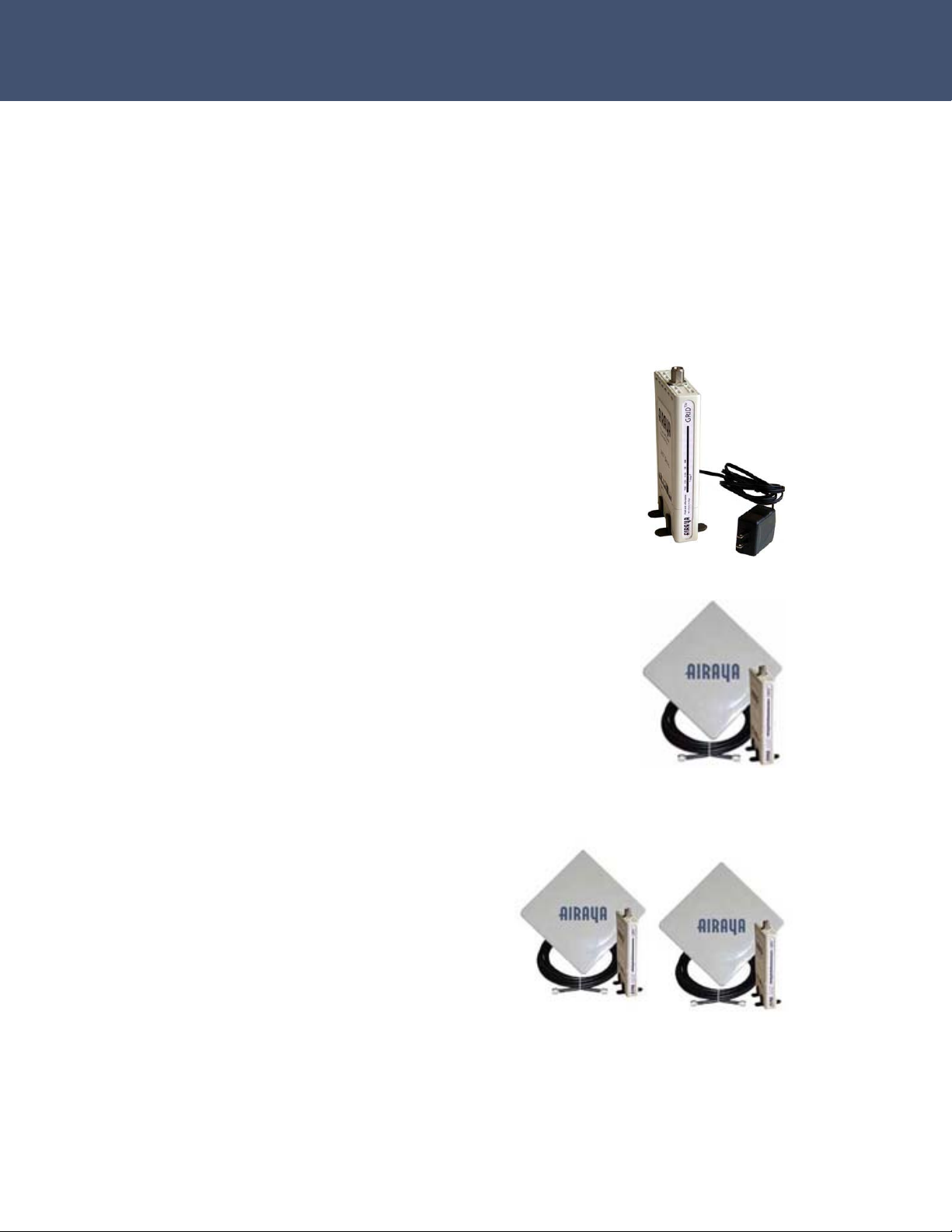
WirelessGRID Indoor Wireless Bridge
(For use with outdoor antennas and RF cables)
Indoor Bridge with
N-type Connector
AI108-4958-N
Indoor Bridge w/RF Cable
and Outdoor Antenna
AI108-4958-1/AI108-4958-SU
Indoor Bridge Kit w/RF
Cables & Outdoor
Antennas
AI108-4958-Kit
Revision 1.01
03/07/2006 3:48 AM
- 1 -

Airaya – Fast and affordable outdoor wireless bridges
AIRAYA is a trademark of AIRAYA Corp. Other trademarks or brand names
mentioned herein are trademarks or registered trademarks of their
respective companies.
International Headquarters
637 Adair Court
Morgan Hill, CA 95037
Tel: 866-224-7292
Tel: 408-776-9583 International
Fax 408-776-9583
E-mail: support@airaya.com
Skype: airaya_support
Web site: www.airaya.com
Copyright © 2004 by AIRAYA Corp. All rights reserved.
No part of this document may be copied or reproduced in any form or by
any means without the prior written consent of AIRAYA Corp.
AIRAYA makes no warranties with respect to this documentation and
disclaims any implied warranties of merchantability, quality, or fitness for
any particular purpose. The information in this document is subject to
change without notice. AIRAYA reserves the right to make revisions to this
publication without obligation to notify any person or entity of any such
changes.
- 2 -

Airaya – Fast and affordable outdoor wireless bridges
Limited Warranty
AIRAYA Corp.
Limited Warranty: AIRAYA warrants all of its products to be free of
manufacturing defects in workmanship and materials, under normal use
and service, for the applicable warranty term. All AIRAYA products carry a
standard 90-day limited warranty from the date of purchase from AIRAYA
or its Authorized Reseller. AIRAYA may, at its own discretion, repair or
replace any product not operating as warranted with a similar or
functionally equivalent product during the applicable warranty term.
The standard limited warranty can be upgraded to a one-year warranty by
registering new products within 30 days of purchase from AIRAYA or its
Authorized Reseller. Registration can be accomplished online via the
AIRAYA web site. Failure to register will not affect the standard limited
warranty. The one-year warranty covers a product during the Life of that
Product, which is defined as the period of time during which the product is
an ‘Active’ AIRAYA product. A product is considered to be ‘Active’ while it
is listed on the current AIRAYA price list. As new technologies emerge,
older technologies become obsolete and AIRAYA will, at its discretion,
replace an older product in its product line with one that incorporates
these newer technologies. At that point, the obsolete product is
discontinued and is no longer an ‘Active’ AIRAYA product.
All products that are replaced become the property of AIRAYA.
Replacement products may be either new or reconditioned. Any replaced
or repaired product carries either a 30-day limited warranty or the
remainder of the initial warranty, whichever is longer. AIRAYA is not
responsible for any custom software or firmware, configuration
information, or memory data of Customer contained in, stored on, or
integrated with any products returned to AIRAYA pursuant to any
warranty. Products returned to AIRAYA should have any customer-installed
accessory or add-on components removed prior to returning the product
for replacement. AIRAYA is not responsible for these items if they are
returned with the product.
Customers must contact AIRAYA for a Return Material Authorization (RMA)
number prior to returning any product to AIRAYA. Proof of purchase may
be required. Any product returned to AIRAYA without a valid RMA number
clearly marked on the outside of the package will be returned to customer
at customer’s expense. Customers are responsible for all shipping charges
from their facility to AIRAYA. AIRAYA is responsible for return shipping
charges from AIRAYA to the customer.
- 3 -

Airaya – Fast and affordable outdoor wireless bridges
Limited Warranty
WARRANTIES EXCLUSIVE: IF AN AIRAYA PRODUCT DOES NOT OPERATE
AS WARRANTED ABOVE, CUSTOMER'S SOLE REMEDY SHALL BE REPAIR
OR REPLACEMENT OF THE PRODUCT IN QUESTION, AT AIRAYA’S OPTION.
THE FOREGOING WARRANTIES AND REMEDIES ARE EXCLUSIVE AND ARE
IN LIEU OF ALL OTHER WARRANTIES OR CONDITIONS, EXPRESS OR
IMPLIED, EITHER IN FACT OR BY OPERATION OF LAW, STATUTORY OR
OTHERWISE, INCLUDING WARRANTIES OR CONDITIONS OF
MERCHANTABILITY AND FITNESS FOR A PARTICULAR PURPOSE. AIRAYA
NEITHER ASSUMES NOR AUTHORIZES ANY OTHER PERSON TO ASSUME
FOR IT ANY OTHER LIABILITY IN CONNECTION WITH THE SALE,
INSTALLATION, MAINTENANCE OR USE OF ITS PRODUCTS. AIRAYA SHALL
NOT BE LIABLE UNDER THIS WARRANTY IF ITS TESTING AND
EXAMINATION DISCLOSE THE ALLEGED DEFECT IN THE PRODUCT DOES
NOT EXIST OR WAS CAUSED BY CUSTOMER'S OR ANY THIRD PERSON'S
MISUSE, NEGLECT, IMPROPER INSTALLATION OR TESTING,
UNAUTHORIZED ATTEMPTS TO REPAIR, OR ANY OTHER CAUSE BEYOND
THE RANGE OF THE INTENDED USE, OR BY ACCIDENT, FIRE, LIGHTNING,
OR OTHER HAZARD.
LIMITATION OF LIABILITY: IN NO EVENT, (INCLUDING NEGLIGENCE),
SHALL AIRAYA BE LIABLE FOR INCIDENTAL, INDIRECT, SPECIAL, OR
PUNITIVE DAMAGES OF ANY KIND, OR FOR LOSS OF REVENUE, LOSS OF
BUSINESS, OR OTHER FINANCIAL LOSS ARISING OUT OF OR IN
CONNECTION WITH THE SALE, INSTALLATION, MAINTENANCE, USE,
PERFORMANCE, FAILURE, OR INTERRUPTION OF ITS PRODUCTS, EVEN IF
AIRAYA OR ITS AUTHORIZED RESELLER HAS BEEN ADVISED OF THE
POSSIBILITY OF SUCH DAMAGES.
SOME COUNTRIES DO NOT ALLOW THE EXCLUSION OF IMPLIED
WARRANTIES OR THE LIMITATION OF INCIDENTAL OR CONSEQUENTIAL
DAMAGES FOR CONSUMER PRODUCTS, SO THE ABOVE LIMITATIONS AND
EXCLUSIONS MAY NOT APPLY TO YOU. THIS WARRANTY GIVES YOU
SPECIFIC LEGAL RIGHTS, WHICH MAY VARY FROM STATE TO STATE.
NOTHING IN THIS WARRANTY SHALL BE TAKEN TO AFFECT YOUR
STATUTORY RIGHTS.
Note: AIRAYA will provide fee-based service for up to three years
following discontinuance of any product from the active AIRAYA price list.
Under the one-year warranty, internal and external power supplies, and
fans are covered by a standard one-year warranty from date of purchase.
- 4 -

Airaya – Fast and affordable outdoor wireless bridges
Regulatory Information
FCC and Industry Canada Guidelines
The radiated output power of the AIRAYA WirelessGRID Wireless Bridge is far
below the FCC radio frequency exposure limits. Nevertheless, the device shall
be used in such a manner that the potential for human contact during normal
operation is minimized. It is the responsibility of the installer and users of the
WirelessGRID to guarantee that the antenna operates at least 20 centimeters
(8 inches) from any person. This is necessary to insure that the product
operates in accordance with the Federal Communications Commission’s RF
Guidelines for Human Exposure.
The WirelessGRID’s built-in antennas may NOT be replaced at any time. They
are designed to comply with the maximum EIRP limits specified by the FCC
and Industry Canada. Modifications to the WirelessGRID, unless expressly
approved by AIRAYA, could void the user's authority to operate the equipment.
The WirelessGRID wireless bridge operates in the 5.25 to 5.35 GHz frequency
range. High power radar systems in both Canada and the United States are
allocated as primary users of this spectrum. These radars can cause
interference and or damage to devices such as the WirelessGRID wireless
bridge when used outdoors.
The term “IC:” before the radio certification number only signifies that
Industry Canada technical specifications were met.
FCC ID: QDE-GRIDC3
IC: 4433A-GRIDC3
THIS DEVICE COMPLIES WITH PART 15 OF THE FCC RULES. OPERATION
IS SUBJECT TO THE FOLLOWING TWO CONDITIONS: (1) THIS DEVICE
MAY NOT CAUSE HARMFUL INTERFERENCE, AND (2) THIS DEVICE MUST
ACCEPT ANY INTERFERENCE RECEIVED, INCLUDING INTERFERENCE THAT
MAY CAUSE UNDESIRED OPERATION.
NOTE: This equipment has been tested and found to comply with the limits for a Class A
digital device, pursuant to Part 15 of the FCC Rules. These limits are designed to provide
reasonable protection against harmful interference when the equipment is operated in a
commercial environment. This equipment generates, uses, and can radiate radio frequency
energy and, if not installed and used in accordance with the instruction manual, may cause
harmful interference to radio communications. Operation of this equipment in a residential
area is likely to cause harmful interference in which case the user will be required to correct
the interference at his or her own expense.
Class A Digital Compliance
- 5 -

Airaya – Fast and affordable outdoor wireless bridges
Frequency Stability Statement
The 40 MHz crystal provides the core clock for the AR2313 and AR5112. This crystal
is attached to the AR5112, witch then internally forms an oscillator. The AR5112
then provides the output of the oscillator to its internal frequency synthesizer, and
to the AR2313.
The maximum frequency tolerance allowed by the IEEE 802.11 standard is ±20
ppm. Therefore, the crystal device needs to meet this requirement over all
operating conditions. Atheros recommends a crystal device with an overall
tolerance of 18 ppm that includes initial tolerance, tolerance over operating
temperature range, and aging tolerance.
The crystal device used in the Reference Design is calibrated at 15 pF load. When
designing the crystal circuit, care should be taken to include the board stray and
other capacitances, such as those inherent with the oscillator circuits, in the overall
calculation of the load capacitance.
- 6 -

Airaya – Fast and affordable outdoor wireless bridges
Contents
Introduction .............................................................................................. 9
Package Checklist.................................................................................... 9
Hardware Description................................................................................ 10
Ethernet Compatibility ........................................................................... 10
Radio Characteristics ............................................................................. 10
Antenna Type ....................................................................................... 10
Backhaul / Point-to-point Architecture ......................................................... 11
Multipoint Architecture .............................................................................. 11
Repeater Architecture ............................................................................... 11
Mesh Architecture .................................................................................... 12
AI108-4958-Kit, -1, -SU, and -N Connection Diagram.................................... 12
System Requirements ............................................................................... 13
Hardware Installation................................................................................ 14
Indoor Bridge Connections...................................................................... 14
Installing and Visually Aligning Outdoor Antenna .......................................... 16
Software Configuration ............................................................................. 18
Getting Started ..................................................................................... 18
Logging into the WirelessGRID NMS ......................................................... 18
Current Settings ................................................................................... 19
WirelessGRID System Setup Tab ............................................................. 22
Network Settings Tab ............................................................................ 24
Radio Settings Tab ................................................................................ 26
Admin Setup Tab .................................................................................. 29
Security Tab –Authentication and Data Encryption ..................................... 32
WirelessGRID Authentication .................................................................. 32
Data Encryption .................................................................................... 33
Encryption Key Manager......................................................................... 34
Security Server (RADIUS) Settings .......................................................... 36
Active Bridge Status Tab ........................................................................ 37
Remote Bridge (SU Station) Statistics Tab ................................................ 38
Firmware Update Tab............................................................................. 41
- 7 -

Airaya – Fast and affordable outdoor wireless bridges
Help Tab .............................................................................................. 42
Antenna alignment and link monitoring tool ................................................. 43
Check List for Antenna Alignment ............................................................ 43
Using the real-time signal strength monitor for antenna alignment ............... 44
Antenna Adjustment Using the real-time Signal Strength Monitor................. 46
Specifications .......................................................................................... 47
Ordering Information ................................................................................ 49
WirelessGRID Worldwide Frequency Channel Plan ......................................... 50
Appendix A – Bench Test Procedure ............................................................ 51
Step 1. Setup a wired Ethernet network between test stations..................... 51
Step 2. Setup wired Ethernet network connections to bridges ...................... 52
Step 3. Setup bridge software configuration for bridge ............................... 54
Step 4. Test network connectivity across a WirelessGRID link ...................... 55
Step 4a. Check throughput of WirelessGRID link (optional) ......................... 56
Step 5. Running the real-time Signal Strength Monitor ............................... 57
Step 6. Field deployment of WirelessGRID bridges ..................................... 58
Appendix B. Multi-point Bridge Configuration Log......................................... 59
Appendix C: Weatherproofing RF Cable Connections...................................... 60
How to Get Help....................................................................................... 61
Worldwide Web Support ......................................................................... 61
Contacting AIRAYA ................................................................................ 61
- 8 -

Airaya – Fast and affordable outdoor wireless bridges
Introduction
AIRAYA WirelessGRID series wireless bridges have been designed to
provide transparent, high-speed data communications between two to 32
locations. Point-to-point, multipoint, and repeater functionality are built
into all AIRAYA WirelessGRID broadband wireless access products.
This solution offers fast, reliable wireless connectivity with considerable
cost savings compared to wired alternatives. Utilizing proprietary 5 GHz
technology, WirelessGRID bridges easily replace Ethernet or T1
connections or seamlessly integrate into a newer 100 Mbps Ethernet Local
Area Network (LAN).
Package Checklist
Each AI108-4958-N comes in one carton and contains the following
components:
One indoor bridge unit with N-type female connector
One 6 foot straight-through Ethernet cable
One 120V AC Power Supply (Full range option available)
This installation manual
NOTE
Two AI108-4958-N bridges must be used to create a link between
two locations. In addition, an RF cable and antenna must be
purchased separately for each AI108-4958-N
Each AI108-4958-1 or AI108-4958-SU comes in one carton and
contains the following components:
One AI108-4958-N units with N-type female
connectors
One 23 dBi antenna with N-type female connector
& mounting bracket
One 25 foot LMR-400 cable with N-type male
connector
This installation manual
- 9 -

Airaya – Fast and affordable outdoor wireless bridges
Each AI108-4958-Kit comes in one carton and contains the following
components:
Two AI108-4958-N units with N-type
female connectors
Two 23 dBi antennas with N-type
female connectors & mounting
brackets
Two 25 foot LMR-400 cables with N-
type male connectors
This installation manual
Please register your product online at: www.airaya.com in the support/
product registration section of our web site. Note: Free technical support
is only available to registered users of AIRAYA equipment.
Please inform your dealer if there are any incorrect, missing, or damaged
parts. If possible, retain the carton and original packing materials for
repacking purposes in case you need to return the bridge for repair.
Hardware Description
Ethernet Compatibility
Each AIRAYA WirelessGRID wireless bridge can be attached directly to a
10BASE-T/100BASE-TX (twisted-pair) Ethernet LAN segment. These
segments must conform to the IEEE 802.3 specification.
Radio Characteristics
The WirelessGRID bridge utilizes a radio modulation technique known as
Orthogonal Frequency Division Multiplexing (OFDM) and is capable of
operating in the 4.9 GHz to 5.850 GHz frequency range with 5, 10, 20, or
40 MHz wide channels. Data is transmitted over a half-duplex radio
channel at speeds of up to 108 Mbps.
Antenna Type
The AI108-4958-kit comes with 23 dBi patch antenna and 28 dBi dish
antennas that operate in the 5.15-5.850 GHz frequency range.
For international and military markets, the AI108-4958-N can be used with
external antennas options and radio output power between 6 and 21 dBm.
Please contact AIRAYA for additional antenna options. Local regulations apply.
- 10 -
Airaya – Fast and affordable outdoor wireless bridges
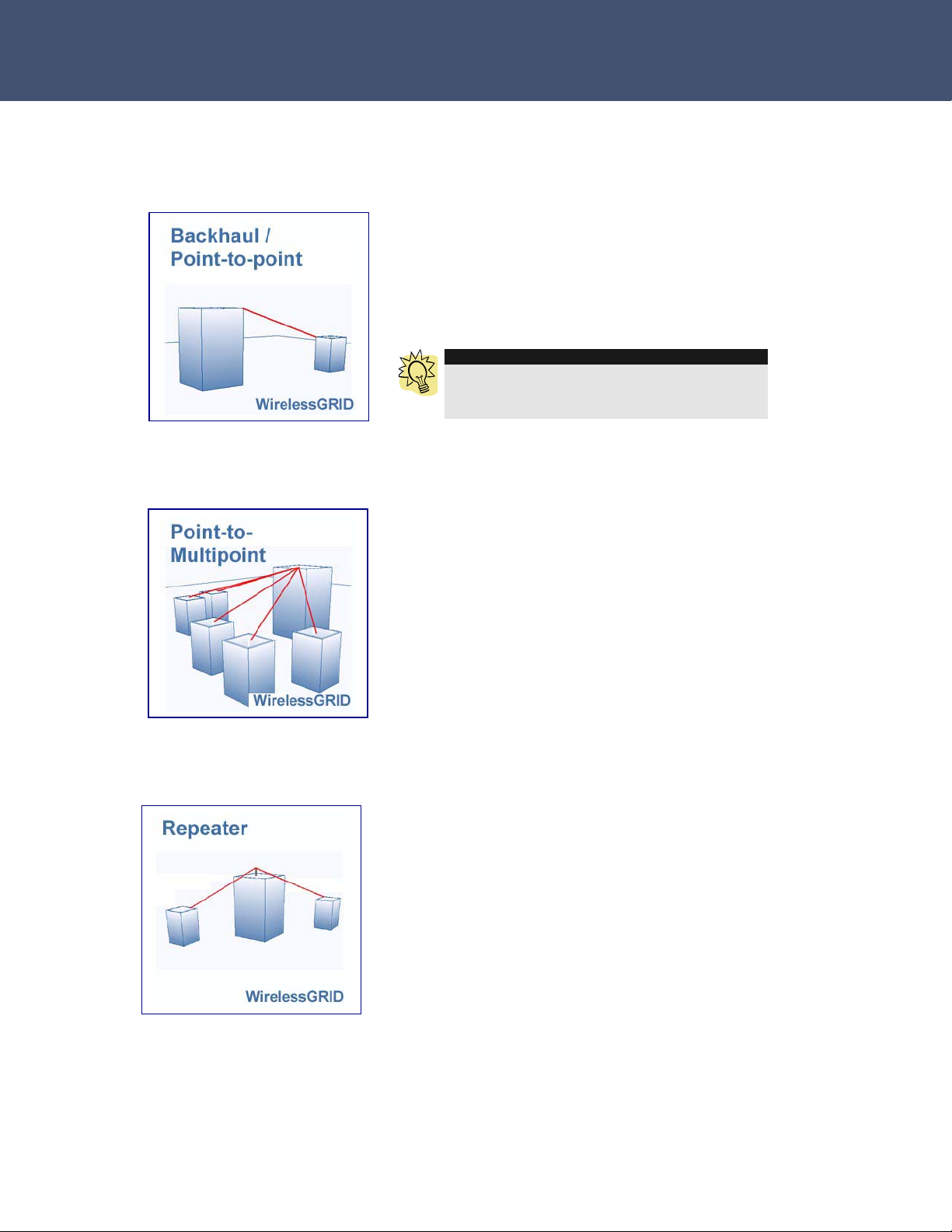
Backhaul / Point-to-point Architecture
Figure 1.
This diagram illustrates a typical
use scenario of a WirelessGRID bridge
interconnecting two networks in separate
buildings.
F
TIP
Utilizing two properly configured links on the
same path will provide redundancy and double
throughput between locations.
Multipoint Architecture
Figure 2. This diagram illustrates a typical use
scenario of a WirelessGRID outdoor base station
connecting to multiple subscriber units at
different locations in a city. Up to 32 subscriber
units can be connected to one base station.
WirelessGRID point-to-point and multipoint
functionality can be combined to form a
broadband wireless infrastructure.
Repeater Architecture
Figure 3. This diagram illustrates the use of an
AI108-4958-ON2 repeater/base station. The
single radio repeater configuration requires two
antenna/cable assemblies to one pointing toward
the building to the left and one pointing toward
the building to the right. Alternatively, this
product can be used as a base station with two
sector antennas to increase the coverage area
wider horizontal plane. For example, two 120
sector antennas attached to the AI108-4958-ON2
would provide a 240
- 11 -
o
degree coverage area.
o
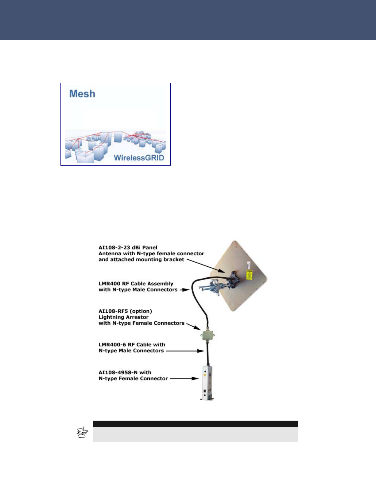
Airaya – Fast and affordable outdoor wireless bridges
Mesh Architecture
Figure 4. This diagram illustrates the combined
use of WirelessGRID backhaul, repeater and
multi-point equipment to cover a large
geographic area, creating a mesh network.
For complete information on model numbers,
please refer to the ordering guide on page 57.
AI108-4958-Kit, -1, -SU, and -N Connection Diagram
Figure 5. This diagram illustrates a typical bridge configuration.
NOTE
All outdoor RF connections should be weather-sealed. Please refer to
Appendix C for instructions on weatherproofing RF connections
- 12 -

Airaya – Fast and affordable outdoor wireless bridges
System Requirements
Before installing the AI108-4958-N, AI108-4958-SU, AI108-4958-1, or
AI108-4958-Kit, be sure you have the following items on-hand:
An AC power outlet (100 to 120 V, 50 to 60 Hz) or (optional 100-
220 V, 50 to 60 Hz) to supply power to each indoor bridge unit
An outdoor antenna mast with a 1 to 6 inch (25.4 to 152.4 mm)
diameter, or a suitable wall mount location and screw-in anchors,
molly bolts, or pan-head screws to attach antenna mounting bracket
An available RJ-45 (UTP) port on a 10/100 Mbps Ethernet switch or
router
Web browser for software configuration
The WirelessGRID bridge has been designed to withstand normal handling
procedures, but reasonable precautions should be taken during
installation, particularly with regard to static discharge.
• Make sure that you are adequately grounded by touching the bare
metal surface on the back of a computer or networking device
before installing bridge.
• Avoid moving around the work area in order to eliminate static
charge buildup.
• If possible, do not work on a carpeted area.
- 13 -

Airaya – Fast and affordable outdoor wireless bridges
Hardware Installation
Indoor Bridge Connections
Figure 5. Front and
rear panel views
The AI108-4958-N, AI108-4958-1, or AI108-SU connect to your network with a
standard 100/10 Mbps Ethernet cable; and connects to the outdoor antenna
using an RF cable. The AI108-4958-N, -1, -SU units features the following LED
status indicators:
LED Indication
Power LED Blinks while bridge is powering up and performing power-on
self-test. While bridge is ready, LED remains on without
blinking.
5 GHz LED Indicates the bridge is operating in 4.9-5.85 GHz range. LED
blinks at a different rate in correspondence to the transfer
rate.
2.4 GHz LED Indicates the bridge is operating in 2.4-2.5 GHz. This
functionality is not available in standard configuration.
10M LED
100M LED Indicates the bridge has a physical Ethernet connection and
Rear Panel
Reset button Pressing the reset button and holding it in for more than 4
Indicates the bridge has a physical Ethernet connection and
is linked to your network at 10 Mbps.
is linked to your network at 100 Mbps.
seconds will set the bridge network settings to factory
defaults. Cycle the power to enable new settings.
- 14 -
Airaya – Fast and affordable outdoor wireless bridges
Before you mount the AI108-4958-N, AI108-4958-1, or AI108-SU
to a fixed location, consider the following requirements to
determine the optimal placement:
The RF cable between the AI108-4958-N, AI108-4958-1, or AI108-SU and
the antenna should be as short as possible without putting too much
stress on the connectors at the bridge and antenna. The RF cable
attenuates (reduces) the radio signal and will reduce the effective range
of your wireless link.
The cable length from the Ethernet network port to the AI108-4958-N,
AI108-4958-1, or AI108-SU must not exceed 328 ft (100 meters).
Placement must allow for easy access to disconnect the bridge unit from
the AC power outlet if necessary.
Follow these steps to install the AI108-4958-N, AI108-4958-1, or AI108SU indoor bridge:
1. Connect the Ethernet cable – The AI108-4 and AI108-N should be
connected to a 10/100Mbps Ethernet network through a switch or
router. Alternatively, a computer can be directly connected to the
bridge using an Ethernet cross-over cable. Connect to the RJ-45
connector socket on the back panel of the bridge with 5 UTP
Ethernet cable and an RJ-45 connector.
2. Connect the power adapter cable to the 5V, 2A DC power socket on
the rear panel, and plug the power adapter into the wall outlet.
Warning: Use only the power adapter supplied with the bridge in
order to prevent damage and void warranty.
3. Refer to the section above on LED status indicators to verify the
unit is powered on and functioning properly.
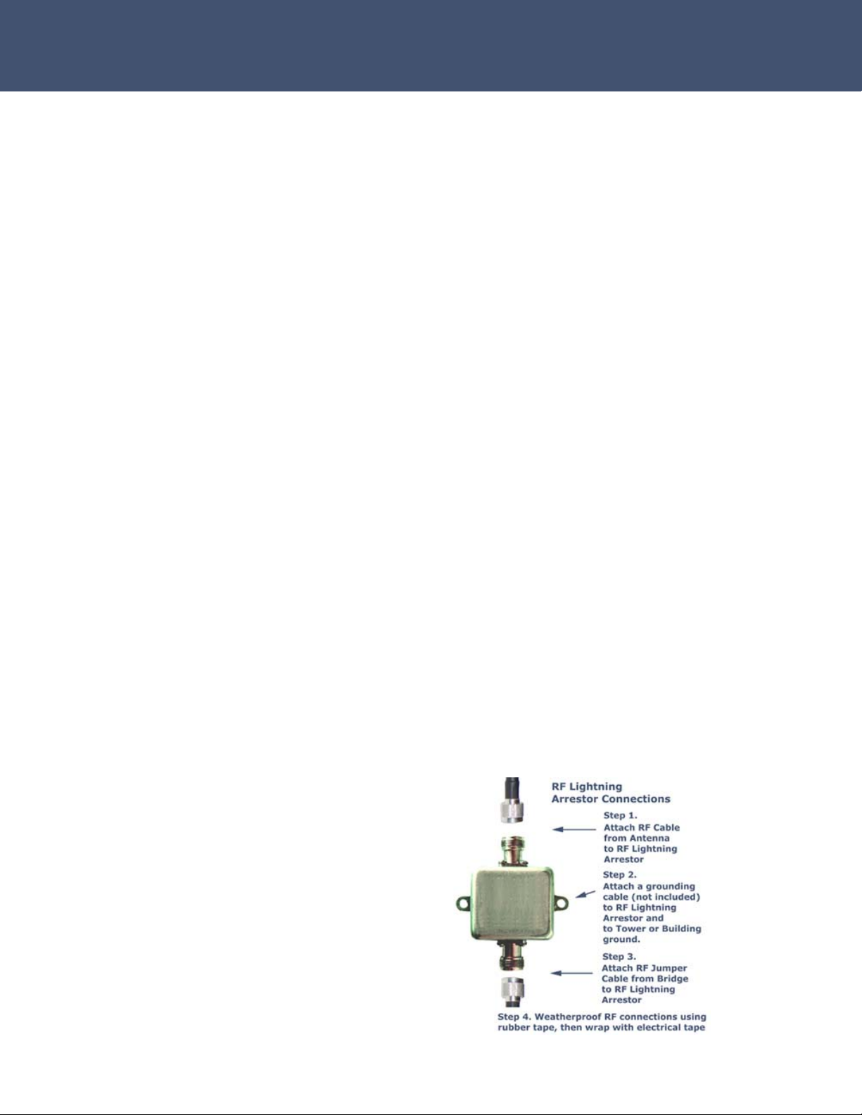
4. Connect the optional
lightning arrestor and
jumper cable assembly
- 15 -
Airaya – Fast and affordable outdoor wireless bridges
Installing and Visually Aligning Outdoor Antenna
To ensure maximum performance and stability of your wireless link, it is
crucial that you determine the right locations for the outdoor antennas
based on the following criteria:
• A good signal path, ideally with visual line of sight and
adequate Fresnel clearance between bridges
• Minimal distance between bridges
• Minimal reflections from other objects.
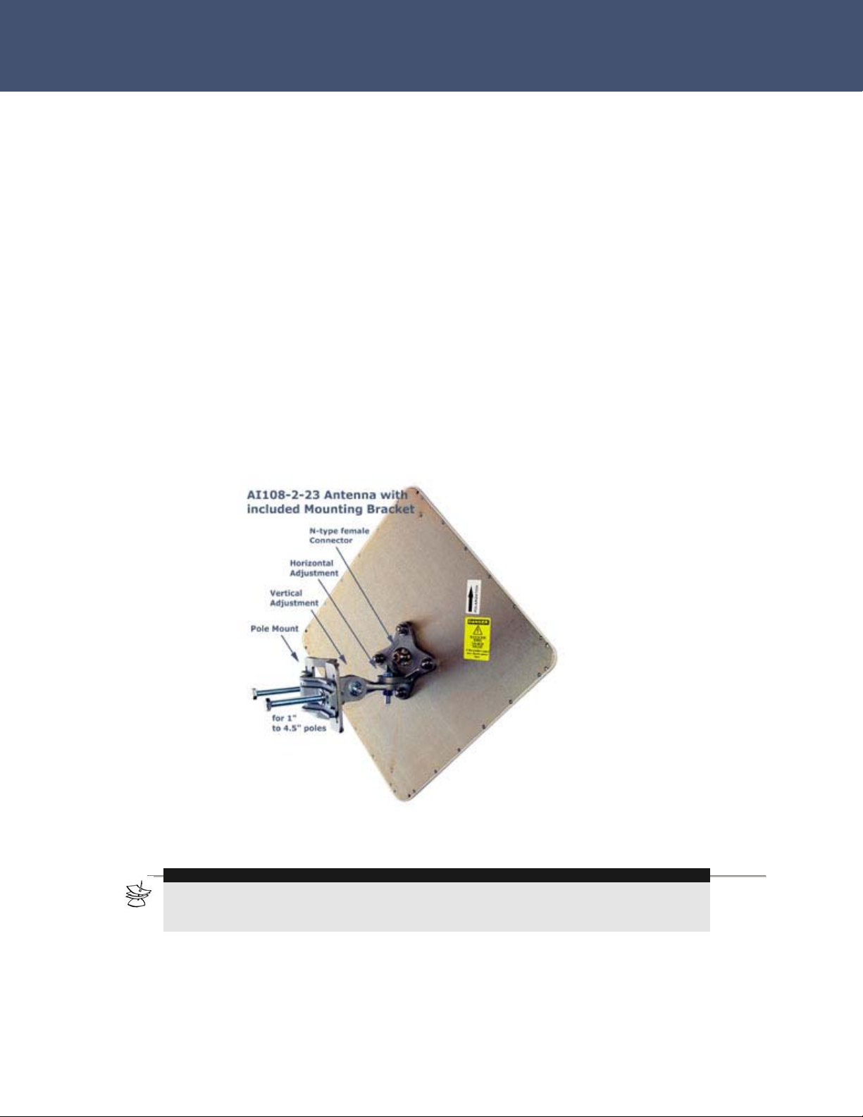
Figure 6. If using 23 dBi directional antennas supplied by AIRAYA, mast
mounting of the external antennas can be accomplished using the included
mounting brackets with full vertical and horizontal adjustment.
NOTE
When wall mounting the antenna to the side of a structure, you will not need the back
portion of the mounting bracket. Use screw-in anchors, molly bolts, or pan-head screws to
attach antenna mounting bracket to side of structure.
- 16 -

Airaya – Fast and affordable outdoor wireless bridges
Follow these steps to install and visually align outdoor antennas:
1. Attach the antenna to a mast or side of a building using the included
bracket.
2. Align the outdoor antenna horizontally: Loosen the horizontal
adjustment bolt and nut to visually aim the antenna at the remote
bridge. Set the appropriate horizontal angle and tighten the horizontal
adjustment bolt and nut so that the angle is locked in place.
3. Align the outdoor antenna vertically: Loosen the vertical adjustment
bolt and nut on the mounting bracket and point the antenna towards
the remote end point. Set the appropriate elevation angle and tighten
the alignment bolts so that the angle is locked in place.
4. Secure the cable along the mast between the outdoor antenna and the
indoor bridge inside your building. Note: We recommend that you
secure the entire cable to the mast at 10-foot intervals.
5. Repeat steps one through four for each remote location outdoor
antenna.
6. Use the real-time Signal Strength Monitor to fine-tune received signal
strength (RSSi) between bridges. This tool is designed to maximize the
throughput of your new WirelessGRID link by providing the highest
possible signal strength across a wireless path. See the section on
“Antenna Alignment and Link Monitoring Tool” for instructions.
TIP
If this is your first installation of an AIRAYA link, AIRAYA recommends that
you perform the bench test procedure in Appendix A before deploying the
product. This will ensure that bridges are functioning properly and fully
configured, and will allow you to become familiar with the tools for aligning
antennas and optimizing throughput before you get into the field.
- 17 -
Airaya – Fast and affordable outdoor wireless bridges
Software Configuration
You can configure the network, radio, and security parameters of the
WirelessGRID bridge using the built-in WirelessGRID Network Management
System (NMS). This web-based configuration utility greatly simplifies the
setup process by allowing you to access all parameters and settings
through a single, consistent user interface.
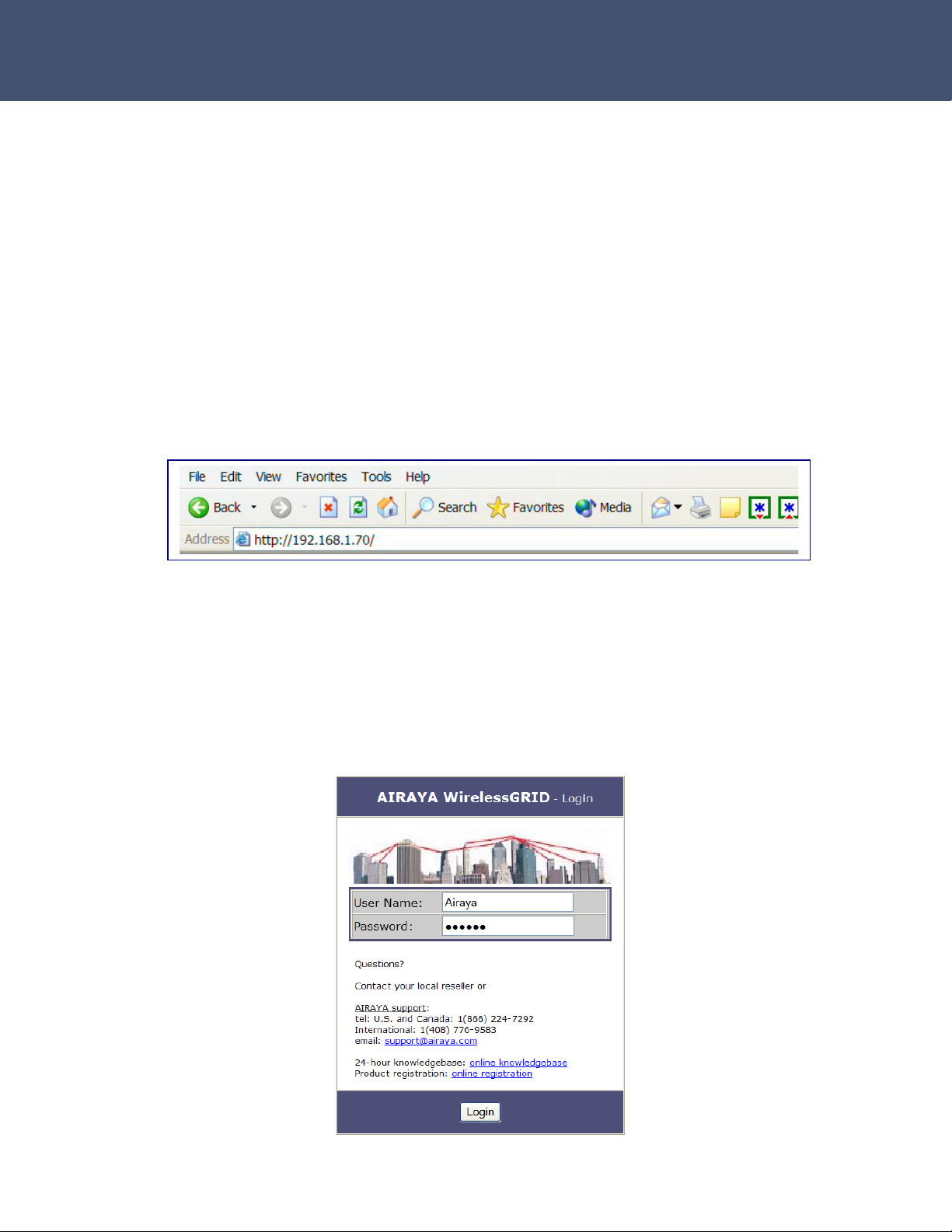
Getting Started
The factory default IP address of the WirelessGRID bridge is 192.168.1.70.
Type that string into the address field of your browser and press the
Return key to load the WirelessGRID NMS.
You will be prompted for a User Name and Password. Refer to the next
section for information about default settings.
Logging into the WirelessGRID NMS
The WirelessGRID bridge requires you to enter a user name and password
to gain access to the configuration utility. The default User Name and
Password is “Airaya.”
- 18 -
Airaya – Fast and affordable outdoor wireless bridges
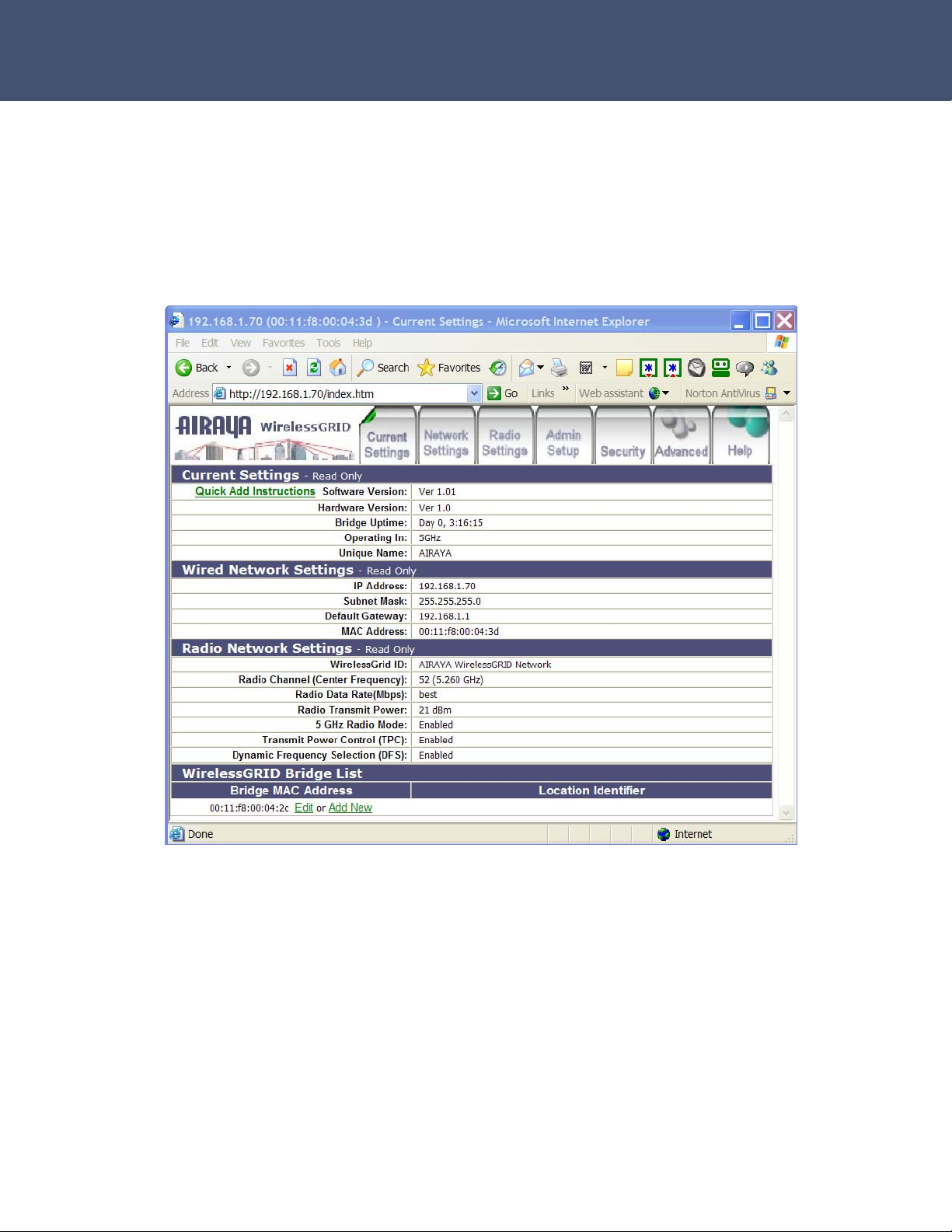
Once logged in, you can access all available WirelessGRID configuration
options. The web interface is organized into tabs that allow you to access
screens that let you view and change bridge parameters.
Tabs include Current Settings, Network Settings, Radio Settings, Admin
Setup, Advanced, WirelessGRID Authentication, Data Encryption, Security
Server, Active Bridges, Station Stats, Download Updates and screen-
specific Help.
The following sections describe the entries in each area of the Current
Settings screen:
Current Settings
Quick Add Instructions – Step-by-step instructions to set up and add a
new bridge to a WirelessGRID network.
Software Revision – Current software (firmware) version installed on the
bridge.
- 19 -
 Loading...