

Page 1
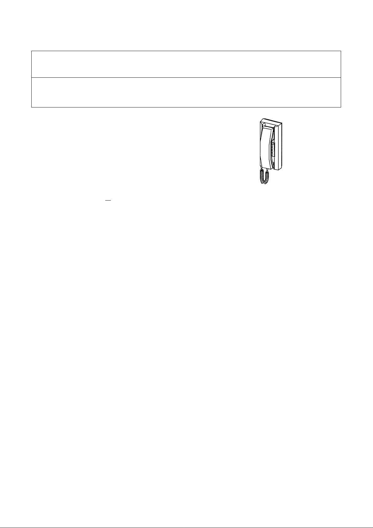
LOOP-WIRED HANDSET INTERCOM
(YAZ PHONE TYPE INTERCOM)
Models: YAZ-90-3W
INSTALLATION & OPERATION MANUAL
This Manual and the Markings on the product
contain various symbois in order that the product
can be used safely and properly, and that the
installer and user are protected from injury and
property damage. The following precautions
must be thoroughly read and understood before
proceeding.
PRECAUTIONS ON INSTALLATION
/K WARNING Negligence could result in death or serious injury to people.
A
CAUTION Negligence could result in injury to people or damage to property.
The following precautions are also applied to YAW-RB adaptors.
833952 02041
®AIPHONE
s
WARNING
A
1. Do not dismantle or alter the unit. Fire or electric
shock could result.
2. Do not connect any power source other than specified
to terminals +, - nor install two power supplies in
parallel to single input. Fire or electric shock could result.
3. Keep the unit away from water or any other liquid.
Fire or electric shock could result.
4. Do not put any metal into the unit though the openings./^
Fire or electric shock or unit trouble could result.
5. Do not plug or unplug with wet hands. /O
Electric shock could result.
6. Do not use DC power supply with a voltage other than
specified. Fire or electric shock could result.
CAUTION
A
1. Before turning on power, make sure wires are not
crossed or shorted. Fire or electric shock could result.
2. When mounting the unit on wall, install the unit in a
convenient location, but not where it could be
jarred or bumped. Injury could result.
3. Do not install or make any wire terminaiions while power
supply is plugged in. It can cause electrical shock or
damage to the unit.
4. Do not manually hold down hook switch while testing
and verifying call tone volume. The call tone is very
loud in earpiece, and could cause hearing damage.
(S)
0
0
0
5. Do not install the unit in any of the following locations.
Fire, electric shock or unit trouble could result.
— Places under direct sunlight, or near heating equipment
that varies in temperature.
— Places subject to dust, oil, chemicals.
— Places subject to moisture and humidity extremes, iOv
such as bathroom, cellar, greenhouse, etc. 'Sk
— Places where the temperature is quite low, such as inside
a refrigerated area or in front of air-conditioner.
6. On products with ground terminals, connect to an earth
ground. Fire or malfunction could result.
A GENERAL PRECAUTIONS
1. The unit is for domestic use only. Do not use outdoors.
2. When wall mounted, the unit may become dusty.
Clean with a soft cloth.
3. In areas where broadcasting station antennas are close by,
the intercom system may be affected by radio frequency
interference.
4. The unit case may become a little warm with use, but this
is not a unit malfunction.
5. If a cellular phone is used close by, the unit may malfunction.
6. Keep the unit more than 1 m away from Radio or TV set.
7. If the intercom station is operated near OA equipment.
Radio or TV, they interactively influence by radio frequency
interference. Carefully select locations for both installation
and operation.
Examples of Symbols;
A
GENERAL
PRECAUTIONS
GENERAL
INSTRUCTIONS
The A mark indicates caution
statement (inci. danger and
warning), which is specifically
shown inside.
The O mark indicates contents
which demands a specific
action shown inside or attached.
0
GENERAL
PROHIBITIONS
DISMANTLE
PROHIBITIONS
1 -
The 0 mark indicates contents
which prohibit a specific action
shown inside or attached.
MOISTURE
PROHIBITIONS
Page 2
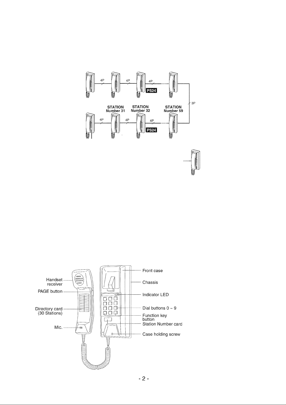
1 SYSTEM OUTLINE & COMPONENTS
YAZ-90-3W is a microprocessor based phone-styie intercom, loop-wired with max. 4 twisted pair wires
throughout system for up to 90 Stations. Each Station can dial 2-digit numbers and communicate with any
other, initiate page to a single zone on one to max. 3 talk channels.
YAZ-90-3W
STATION STATION STATION STATION
Number 10 Number 11 Number 12 Number 29
STATION
Number 30
SYSTEM COMPONENTS
Station unit
YAZ-90-3W
Power supply(24V DC, 2A)
PS-2420S 100 - 240V AC, 50/60Hz.
PS-2420DIN 230V AC. 50Hz.
PS-2420U L 100-240V AC, 50/60Hz.
Paging adaptors
yaVrb
When talkback is included; Release PAGE button and listen.
2 NAMES & FEATURES
4P
STATION
Number 99
3P^
STATION STATION STATION
Number 60 Number 61 Number 62
4P
Phone-Style intercom (max. 90)
Single zone paging adaptor * Each zone requires a paging adaptor, PA amplifier
4P
and a desired number of speakers.
SYSTEM FEATURES
• Max. 90 Stations
• Loop-wired throughout system with
2 to 4-twisted pairs
• 3 talk channels
. Communication privacy
• Incorrect wiring causing malfunction
on a channel, does not affect the
rest of channels
‘ Easy Station Number setting with
dip switch combinations
• Built-in communication functions as
standard, such as call transfer,
camp-on busy, secretary transfer
Page 3
3 INSTALLATION
ACTUAL TERMINAL LOCATION
The connecting terminals are located inside the chassis. Two identical rows of the terminals are provided,
one is to connect incoming wires and the other is to connect outgoing wires.
TT
Jol
Incoming “
la
Inside view of
YAZ-90-3W chassis
SETTING YOUR STATION NUMBER
STATION
mini] : Terminals for 1st talk channel
Connect to terminals 1,2 of the next Station.
: Terminals for 2nd talk channel
Connect to terminals 3, 4 of the next Station,
mjllill ■ Terminals for 3rd talk channel
Connect to terminals 5, 6 of the next Station.
'[±]im ■ Terminals for Power supply
Connect to terminals +, - of the next Station.
Outgoing
STEP #1
Assign a Station number from 10 through 99.
• The YAZ-90-3W system does not require central
exchange unit and, therefore, assigning
Station number must be done on each Station.
• The YAZ-90-3W Station may have any number
from 10 through 99 according to users’
convenience.
• Be sure to assign a Station number for every
installed Station otherwise that Station would not
be able to receive calls.
» Do not assign a same number to more than one
Station.
STATION NUMBER CARD
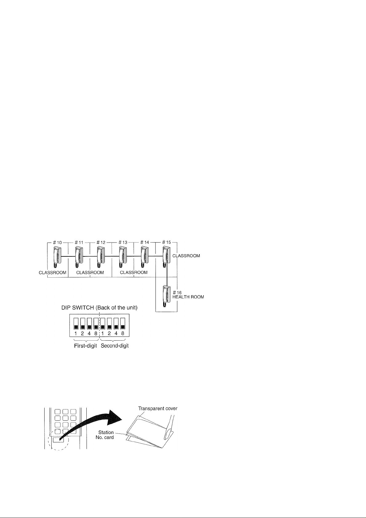
STEP #2
On the DIP SWITCH section (back of the unit),
locate the switches to verify the STATION number
for the station.
Example; STATION #12
1 2 4 8112 4 8
10
' Using the minus-head screwdriver, push either
end of the transparent cover.
> Fill in your Station number programmed on the
card.
:#12
-3-
Page 4

4 WIRING ------------------------------------------------------------------------------------------------------------
1. Cable
Use twisted pair cable, not straight conductors. (Type CPEV, shielded)
(1) YAZ-90-3W station employs such components as CPU(microprocessor) and 1C chips. Twisted pair
cable must be used to prevent the unit from being interfered by line inductive noises generated by
the surrounding electricai appiiances and from crosstalk and malfunction caused by cable
conductors themselves.
(2) Keep at least 30cm (1 ’) away from other cable, like AC power lines, paging speaker lines or
telephone lines, or provide metal conduit for running cable.
2. Wiring distance
The total wiring distance should not exceed 2.9Km (1.8 mile) with 0.8mm dia. cable (20AWG).
(Ii+l2+i3 +
Note; The line loop resistance should not exceed 200 Ohm for communication line between the farthest
...............
stations (Stations 5 and 10) in the system.
£9 +£io\n the below illustration)
DIAMETER
DISTANCE
AWG
DISTANCE
00.5mm
1,100m
24AWG 22AWG 20AWG
0.7 mile
00.65mm
1,900m
1.2 mile
0 0.8mm
2,900m
1.8 mile
3, One power supply is required for every 30 Stations
BLOCK A
STATION
1
No. Of YAZ-90-3W used
Up to 30 stations
From 31 to 60 stations
From 61 to 90 stations
STATION
30
Q! PS-2420
Power supply
required
1 pee
2 pcs
3 pcs
BLOCK B
STATION
60
I'M
DI PS-2420
Location of Power supply
Install a PS-2420 power
supply in the center of each
wiring block of 30 stations.
BLOCK C
STATION
|D|
PS-2420
90
Notes;
• When power supply is installed in each Block:
#1,2 and 3 as shown in the left illustration, do
not connect terminals +, - between each Block.
• The loop resistance of power supply line
between PS-2420 power supply and the
farthest Station in each Block, should be less
than 20 Ohm.
• When locating power supplies for each Block,
count the paging adaptors as follows;
• one YAW-RB single-zone paging adaptor as
5 X YAZ-90-3W Stations.
4. Installation location requirements
In general, observe the installation location requirements as stated in PRECAUTIONS section.
When the YAZ system is installed outside the building, such as ski resort and/or between buildings, etc.
the cable has to be buried under ground in metai conduit. Be sure not to run the cable in midair which
can invite lightning surge and causes permanent damage to the YAZ system.
- 4
Page 5

5 WIRING DIAGRAM
' YAZ-90-3W is a Parallel-wiring system, requiring up to 4-twisted pairs of conductors throughout the system.
STATION
#:[T^
YAZ-90-3W
n y yy
y y y y
12 4 8
12 4 8
STATION
#:[n]
YAZ-90-3W
P
n y yy
n y yy
12 4 8
12 4 8
STATION
#:[12]
YAZ-90-3W
Q y yy
y a y y
12 4 8
12 4 8
STATION
#: [2^
YAZ-90-3W
y a y y
y y y y
12 4 8
12 4 8
STATION
#:
YAZ-90-3W
n y yn
s y y s
12 4 8
12 4 8
" Station#
Terminals #1 & 2
for talk channel
Terminals #3 & 4
for 2nd talk channel
Terminals #5 & 6
for 3'''^ talk channel
IMPORTANT WIRING INSTRUCTIONS
WIRING
• Use twisted pair cable.
• Connect 1st twisted pair to terminals 1 and 2, 2nd twisted pair
to terminals 3 and 4, 3rd twisted pair to 5 and 6 and 4>d twisted
pair to + and -. Do not cross wires.
■ Even if you have extra wires, do not use them for talk line.
Do not connect two or more wires to each number terminal.
PS-2420 POWER SUPPLY CONNECTION
• One PS-2420 power supply is required for every 30 Stations.
' Each PS-2420 power supply must be located near center
of each 30 Station group.
• The + and - lines must not be installed between each groups,
i.e. If the system includes 60 Stations, the 1st pS-2420 should
be connected to Station No.25 and the 2nd PS-2420 to Station
N0.55. Do not connect terminals + and - between Stations
N0S.39 and 40.
• If you have extra wires, it may be used for wiring to +, lines (never for talk lines). It is important, however, the line
resistance on +, - lines is equal as shown in the drawing.
(Pair)
e-
(Pair)
It tc
~n if
jCC3)[
Group 1 Group 2
DO NOT CONNECT
Yes
(Pair)
Yes
-o
(Pair)
No
5-
STATION
#10-39
STATION
#40-69
Page 6

6 MOUNTING
DIP SWITCH (Back of the front case)
YAZ-90-3W unit is designed for wall-mounting and the terminal section is located on inside of
the chassis. Be sure to run cable through conduit or in the wall and mount the YAZ-90-3W
unit onto single-gang box.
Wall-mounting
1. Loosen a screw and separate the front case from chassis.
2. Unplug connector from the receptacle on back of front case.
3. Attach chassis onto single-gang box.
4. Connect wires to the terminals on the chassis attached.
5. Attach connector to the receptacle again.
6. Hook front case to chassis at its top.
7. Attach front case to chassis by the screw.
-6-
Page 7

7 OPERATIONS
SELF-CHECK
1. Pick up handset and dial tone is heard.
2. Press number buttons [o], [T], [T|and [a]. Your station is placed in self-check mode. Busy tone means
your operation is void. Try again.
3. Depress and hold down either number button Q], [2]or|l]to check the corresponding talk channel.
4. A continuous tone means your station is operative. An intermittent tone means your station is
non-operative.
STATION CALLING
1. Pick up handset.
2. Press two dial buttons of station to talk with
(example: [T], [o]for Station #10).
3. Cali by voice, holding down PAGE button in handset.
4. Communicate. At the end, replace handset.
Tremolo tone
Talk as on a telephone after the called station replies.
Busy tone
The station is in communication.
Hang up and call later.
OR
Press [®l button. Camp-on busy is set, and hang up.
(The LED flashes to indicate)
RECEIVING
CALLTRANSFER
COMMUNICATION AMONG 3 STATIONS
(or Call transfer)
CALL TRANSFERRED STATION
[no] •
incoming call is annunciated by either tremolo or voice.
Lift handset and reply.
Note; Tremolo call tone times out in approx, 35 sec.
When you transfer your call with one station to another;
Press button and a Station No. you will transfer the
call to. Hold on until the Station replies.
After talking, hang up.
OR
Press [®l and the Station No.
INTERMITTENT tone means your transfer is being
completed. You may hang up.
To have a third Station to join your present talking, press
[x] button and Station No. to ring. When you hang up,
call transfer is completed.
If your call will not be answered within approx. 18
seconds, it returns to initial two-party conversation.
SECRETARY TRANSFER (Station transfer)
SECTETARY NO.
@ • [^
To have any of incoming calls to be transferred to your
Secretary Station or any designated Station;
Lift handset. Press [®] button and two digits of Secretary
station. Replace handset. Indicator LED flashes on your
Station. Hang up.
To clear;
Press and buttons.
- 7
Page 8

PAGING TO A SINGLE ZONE (when YAW-RB is used)
^ ADAPTOR No. (0 ■9)
iij*./-PAGE button
-i
Lift handset. Press [Xj button.
Press a number button 0 to 9 assigned for YAW-RB.
Transmit your message while holding down PAGE button.
Replace handset.
8 TECHNICAL PRECAUTIONS
Operating temperature
The YAZ-90-3W is rated to operate between temperatures 0°C~ +40°C (32°F ~ 104T).
Cleaning
Clean the YAZ-90-3W equipment with a soft cloth dampened with neutral household cleanser. Never use any abrasive
cleaner or cloth.
At the end of communication, be sure to replace handset on cradle properly. If not, the YAZ-90-3W will not receive a call.
9 SPECIFICATIONS
• Power source
• Current consumption
• Communication
• Talk channel
• Station selection
• Wiring
Wiring distance
Permitted line resistance
: DC 24V. Use a PS-2420 power supply(ies).
: Maximum 80mA (per station). Standby: 25mA.
: Simultaneous with handset.
: Maximum 3 channels.
: 2-digit dial (No.10 ~ 99).
2- twisted pairs in parallel for 1 channel (1- 2, + -“").
3- twisted pairs in parallel for 2 channels (1-2, 3-4, + -““).
4- twisted pairs in parallel for 3 channels (1-2, 3-4, 5-6, + -
: 2.9Km with 0.8mm dia. (1.8 mile with 20AWG) in total.
: Less than 200 Ohm Loop for communication line.
Less than 20 Ohm Loop for power line.
This equipment has been tested and found to comply with the limits for a Class B digital device, pursuant to Part 15 of the FCC Rules.
These limits are designed to provide reasonable protection against harmful interference in a residential installation. This equipment
generates, uses, and can radiate radio frequency energy, and if not installed and used in accordance with the instructions, may cause harmful
interference to radio communications. However, there is no guarantee that interference will not occur in a particular installation.
If this equipment does cause harmful interference to radio or television reception, which can be determined by turning the equipment off and
on, the user is encouraged to try to correct the interference by one or more of the following measures:
•Reorient or relocate the receiving antenna. • Connect the equipment into an outlet on a circuit different from that to which the receiver is
connected. «Increase the separation between the equipment and receiver. • Consult the dealer or an experienced radio/TV technician for help.
•F
^ Aiphone warrants its products to be free from defects of material and workmanship under normal use and service for a period **•
of one year after delivery to the ultimate user and will repair free of charge or replace at no charge, should it become defective ^
upon which examination shall disclose to be defective and under warranty. Aiphone reserves unto itself the sole right to make 4the final decision whether there is a defect in materials and/or workmanship; and whether or not the product is within the
warranty. ^
This warranty shall not apply to any Aiphone product which has been subject to misuse, neglect, accident, or to use in violation
of instructions furnished, nor extended to units which have been repaired or altered outside of the factory. ^
This warranty does not cover batteries or damage caused by batteries used in connection with the unit. X
This warranty covers bench repairs only, and any repairs must be made at the shop or place designated in writing by Aiphone. -t*
Aiphone will not be responsible for any costs incurred involving on site service calls.
AIPHONE CO., LTD., NAGOYA, JAPAN
AIPHONE CORPORATION, BELLEVUE, WA, USA
AIPHONE S.A., WISSOUS, CEDEX, FRANCE
WARRANTY
8-
Oaiphone
Providing Peace of Mind
http://www.aiphone.com/
Printed in Japan (E)
 Loading...