

Page 1

0 AlPHONE
835549 0986 t;
YAZ PHONE TYPE INTERCOM
MODEL: YAZ-90-3 (wall mount)
- INSTRUCTIONS -
YAZ-90-3 is a microprocessor-based intercom, requiring no central exchange unit and with a maximum capability of
90 stations installed per system.
Wiring is accomplished by running 4 twisted pairs in parallel throughout the system, which facilitates ease in installation,
changing location and system expansion.
Various communication functions are standard and the YAZ system is ideal for use in schools, hospitals, offices, public
institutions, factories, banks etc.
NAMES & FUNCTIONS
(T) Handset
(2) Page button
@ Directory card
(4) Indicator LED
Dial buttons ( io]~ )
Function button ( ' ® I , i x J )
(7) Station number card
Optionai terminal
box with cord of
about 2.5 m (8 feet)
Field installation
only)
SYSTEM FEATURES
* Up to 90 phone stations connected in parallel by 4 twisted pairs throughout the system.
* 3 communication channels.
* Incorrect wiring causes mulfunctions of the communication channel concerned but will not affect the remaining two
communication channels.
* Complete communication privacy.
* Intercom unit designed for wall mount. YAK-A terminal box/cord is optional for desk-top use.
* Assigning station number is easily accomplished by just setting a plate on each station.
* A variety of STANDARD communication functions, such as call transfer, camp-on busy, etc. Paging and remote control
operations are available with optional accessories.
BEFORE YOU INSTALL AND OPERATE THE EQUIPMENT
Prohibitions and precautions -
* Operation;
1. DO NOT HOLD HOOK SWITCH DOWN WHILE PICKING UP HANDSET. THE CALL
TONE SOUNDS THROUGH THE HANDSET RECEIVER ELEMENT AND COULD
CAUSE HEARING DAMAGE.
NEVER
Installation;
1. DO NOT CONNECT ANY TERMINAL ON ANY UNIT TO AC POWER LINES.
2. BE SURE TO REMOVE PLUG OF POWER SUPPLY FROM AC OUTLET BEFORE
YOU OPEN THE UNIT OR MAKE WIRING CONNECTIONS.
3. Avoid running the connecting wires thorough doors, windows or between furniture,
which may pinch and disconnect the wires.
4. Installation location requirements on Page 3 must be met.
Maintenance;
1. Clean your intercom equipment with a soft cloth dampened with neutral household
cleanser. Never use thinner nor benzine, etc.
Page 2

YAZ SYSTEM SPECIFICATIONS
Power source
Current consumption
(per station)
Communication
Communication channel
Station selection
Wiring
DC 24V. Use one PS-24N power supply for every 30 stations.
Maximum 150mA.
20mA in standby mode.
Simultaneous by handset.
Maximum 3 channels.
2-digit dial ( [T^ ~ [^ ).
2- twisted pairs in parallel @ >ElI 0 ) ^ communication channel.
3- twisted pairs in parallel ([T] [2^,, [+] ) for 2 communication channels.
4- twisted pairs in parallel (|^ [2],[^ [|^ ,[^ [^, [+] [)|] ) for 3 communication
channels.
Wiring distance
Permitted line resistance
Total wiring distance should not exceed 2.9 km (1.8 mile) with 0.8 mm dia. (20AWG) cable.
Less than 200 ohm. loop for communication line.
Less than 20 ohm loop for power line.
COMPONENTS AVAILABLE FOR USE WITH YOUR YAZ SYSTEM
Station unit Accessories (for optional functions)
€■
u
Power supply
Kg
Accessory
YAZ-90-3: Phone type inter
com, wall mount (3 commu
nication channels).
PS-24N: Power supply
adaptor. OnePS-24Nis
required for every 30 stations.
YAK-A: Terminal box with
cord and connector for desk-top use.
YAW-R: Paging adaptor for
one zone.
YAW-RA: Paging adaptor for
up to 8 zones with multiple
selective zones and all page.
PB-YKX: Talkback adaptor.
Required for each talkback
paging zone.
YAW-S: Remote control
1?.
adaptor for lighting, etc.
'* For details, please refer to the Instructions packed
with each unit.
PRE-INSTALLATION INSTRUCTIONS
1. Use twisted pair cable, not straight conductors.
(1) YAZ-90-3 phone employs such components as CPU (microprocessor) and IC chips. Twisted-pair cable must be used to
prevent the unit from being interfered by line inductive noises generated by the surrounding electrical appliances and
from crosstalk and mulfunction caused by cable conductors themselves.
(2) Keep at least 30 cm (!') away from other cable, like AC power lines or paging speaker lines or telephone lines or provide
metal conduit for running cable.
- 2 -
Page 3
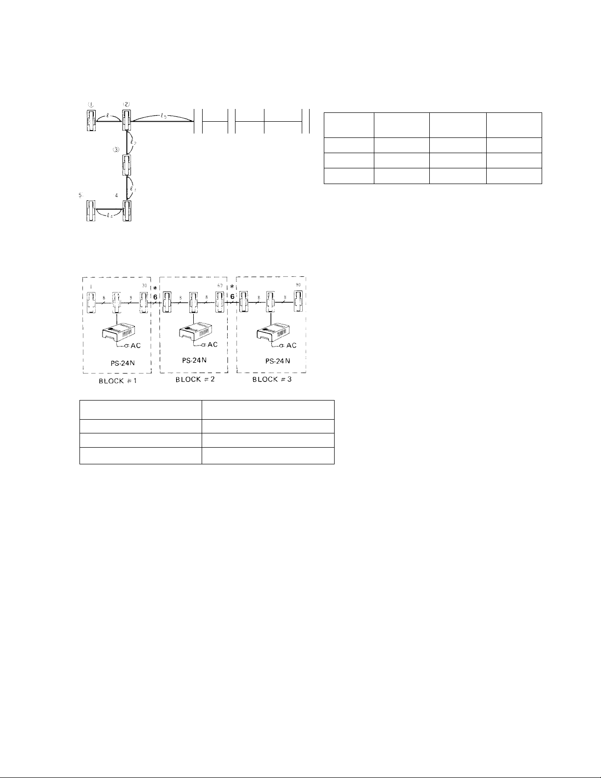
2. The total wiring distance should not exceed 2.9 km (1.8 mile) with 0.8 mm dia. (20 AWG) cable,
(fii +£j +£3 +
...................
£9 +£10 in the below illustration).
f i l
1
P I
1 !
J
i
f\
I
J'
I
3. One power supply is required for every 30 phones.
Diameter
U
of wires
Distance
AWG
Distance 0.7 mile
Note: The line loop resistance should not exceed 200
ohm for communication line between the farthest
phones (stations (5) and ® ) in the system.
*Notes: When power supply is installed in each block: #1,
0.5 mm dia.
1,100 m
24AWG
2 and 3 as shown in the left illustration, do not
connect terminals ^ between each block.
The loop resistance of power supply line between
PS-24 N power supply and the remotest phone in
each block, should be less than 20 ohm.
0.65 mm dia.
1,900 m
22AWG
1.2 mile
0.8 mm dia.
2,900 m
20AWG
1.8 mile
No. of YAZ-90-3 used
Up to 30 stations
From 31 to 60 stations
From 61 to 90 stations
Note: When locating power supplies for each block, please count the adaptors for paging or remote operation of lights as
follows;
* one YAW-R 1-zone paging adaptor as 5 YAZ-90-3 phones.
* one YAW-RA 8-zone paging adaptor as 10 YAZ-90-3 phones.
* one YAW-S remote operation adaptor as 4 YAZ-90-3 phones.
4. Installation location requirements
Do not install YAZ-90-3 phones and power supply to such places as exposed to;
1) high temperature (eg. direct sunlight, air conditioning heat, furnace, etc.)
2) low temperature (eg. refrigirated warehouse).
3) extremely high humidity.
4) water, oil, dust, chemicals, etc.
5) When the system is installed outside the building, such as ski resort and/or between buildings, etc. the cable has to be
buried under ground in metal conduit. Be sure not to run the cable in the sky which invites lightning surge and causes
permanent damage to the system.
Power supply required
1 pee
2 pcs
3 pcs
Install PS-24N power supply in the center
of each block (30 stations)
Location of Power supply
-3 -
Page 4

ACTUAL TERMINAL LOCATION
The connecting terminals are located inside the chassis. Two rows of the terminals are provided, one is to connect
incoming wires and the other is to connect outgoing wires.
nr
A
pmm
[HE (terminals for second communication channel)
jpSE
(terminals for first communication channel)
Connect to terminals 1 i | 2 |of the ne.xt station.
Connect to terminals a P iof the next station,
(terminals for third communication channel)
Connect to terminals J] )6]of the next station.
_[T]rri (power supply terminals)
— — Connect to terminals ri f- the next station.
INSIDE VIEW OF YAZ-90-3 CHASSIS
SETTING YOUR STATION NUMBER
STEP # I: Assign station number from 10 through 99.
STATION
n
CLASSROOM CLASSROOM
CLASSROOM
I
CLASSROOM
ASS
u
HEALTH ROOM
• YAZ-90-3 system does not require central exchange
unit and, therefore, assigning station number must be
done on each station.
• The YAZ-90-3 station may have any number from
through 199j according to the users’ convenience.
• Be sure to assign a station number of every station installed otherwise that station would not be able to receive calls.
• Do not assign the same number to more than one station.
• Alphabets^ to]j^on the plates should remain unused.
• In case two plates touch each other, cut off the remaining end.
STEP # 2: Attach the No. -setting plate (provided in the case) to the socket on back of each unit.
Select 2 plates for each phone
Remove cover of the socket.
ON BACK OF
FRONT CASE
Separate the plates.
station.
For station # 12, select digit
#[f]and[2].
First, separate cahassis from
front case.
Attach the plate to the socket.
For station # 12
[FIRST',!]
SECOND
STATION NUMBER CARD
For station # 20
"FIRST
Please attach the plates so that
the station numbers' digits are
upright.
It Is not necessary to use any
plate for digit [5] ■
(s) Replace the cover.
the transparent cover.
------
FIRST DIGIT
i
-----
SECOND DIGIT
Page 5

MOUNTING INSTALLATION
* Wall-mounting;
YAZ-90-3 unit is designed for wall-mounting and the terminal section is located on the chassis. Be sure to run cable
through the conduit or in the wall and mount the YAZ-90-3 unit onto the one-gang electrical box.
(T) Remove a screw and (¿) Remove connector
separate the front case
from the chassis.
from the receptacle
on back of the front case.
Attach the chassis onto
the one-gang electrical box.
(?) Connect wires to the
terminals on back of the
chassis.
(5) Attach connector to
the receptacle again.
YAK-A TERMINAL BOX INSTALLATION
Hook the front case
to the chassis at its top.
(T) Attach the front case
to the chassis.
When you wish to use a YAZ-90-3 phone station on your desk, please use terminal box complete with cord
and connector, Model: YAK-A, which must be ordered separately.
(D Remove a screw.
O C o
u or
G C C
G D o
@ Pass the YAK-A’s connector through either top
or bottom hole and anchor the cable by the
screw removed in Step 4.
@ Remove a connector.
@ Fix the connector on
the chassis by tape, etc.
Attach the connector to the
receptacle.
(7) Remove a screw (3 x 8mm),
self-tapping) fixing the clamp.
* Wall mounting installation;
(T) Remove a screw and
separate cover.
@ Attach the terminal
case to 1-gang box or wall
with the supplied screws.
5 -
Connect wires.
(4) Replace the cover.
Be careful not to pinch
wires between connectors.
Page 6

WIRING DIAGRAM
STATION #@)
---------
STATION #(25)
STATION # (3^ STATION #
* YAZ-90-3 is a parallel-wiring system, requiring only 4 twisted-pairs of conductors throughout the system.
Terminals Nos.Q] and [^for first communication channel.
Terminals Nos.[s] and [^for second communication channel.
Terminals Nos.[5] and [^for third communication channel.
Terminals Nos.[+] and for power supply.
STATION # (99)
IMPORTANT WIRING INSTRUCTIONS
(1) WIRING;
* Use twisted pair cable.
* Connect first twisted pair to terminals [T] , second twisted pair to terminals [S] , third twisted pair to ^ ^ and
forth twisted pair to[T] [J . Do not cross wires.
* Even if you have extra wires, do not use them for communication line (Do not connect two or more wires to each number
terminal).
(2) PS-24N POWER SUPPLY CONNECTION
* One PS-24N power supply is required for every 30 stations.
* Each PS-24N power supply must be located near the center of each 30 station group.
* Jp' and #-) lines must not be installed between 30 station groups, i.e. If the system includes 60 stations the first
PS-24N should be connected to station No. 25 and the second PS-24N to station No. 55. Do not connect terminals[T]
and py between stations Nos. 39 and 40.
* If you have extra wires, it may be used for wiring to [T] [)p lines (never for communication lines). It is important, how
ever, the line resistance on p] p(] lines is equal. See drawing below.
Group 1 Group 2
Too NOT CONNECTi
ex. STATION STATION
[T^-[3^ |40l-r^
Page 7

SELF-CHECK OPERATION
1. Pick up handset and dial tone is heard.
2. Press number buttons |5] > 1X1 > [1] > [3 ^nd , which sets your station in self-check mode.
Busy tone means your operation is void. Try again,
3. Depress and hold down either number button [T] > IXl or corresponding to communication channel desired to check.
* A continuous tone means your station is operative.
* An intermittent tone means your station is defective.
OPERATIONS
1. CALLING & COMMUNICATION
CALLING
OPERATION
1. Pick up handset.
2. Press two dial buttons of
MODE OF THE CALLED STATION
ACTION
Talk as on the telephone after
the called station replies.
desired station (i.e.j 1 j 0 ;for
station #10).
3. To call by voice, depress page
button in handset.
4. After communication, hang up
handset.
The station is communicating with
other station.
H^OR Press button for setting
Hang up handset and call later.
camp-on busy and hang up
handset (Indicator LED flashes
upon hanging up handset).
RECEIVING
Incoming call is announced by either tremolo tone or by voice. To reply, simply pick up handset.
2. CALL TRANSFER
When you transfer your call with one station to another,
1. Press [^button and the station number to which you are transferring the call.
When the station replies, hang up handset.
OR
2. Press @ button and the station number, intermittent tone means the transfer is completed and you may hang up handset.
3. COMMUNICATION AMONG 3 STATIONS
When you wish to have the third station join the conversation being held, press QL button and the third station number
(If your call to a third station is not picked up in 15 seconds, it will automatically return to the initial communication bet
ween the first two stations).
4. SECRETARY TRANSEER (STATION TRANSEER)
When you wish any of incoming calls to be received by your secretary or other designated station,
1. Pick up handset,
2. Press button and the two dial buttons of secretary station.
3. Hang up handset.
4. Indicator LED on your station starts to flash when you hang up handset.
* To clear Secretary (Station) Transfer mode;
Press and buttons at your station.
5. PAGING WITH YAW-R
1. Pick up handset.
2. Press Q-:J button.
3. Press a dial button (0 — 9) of YAW-R number assigned (No. )
4. Page while depressing page button in handset.
5. Release page button in handset to listen, when talkback is included.
6. Hang up handset.
-7-
Page 8

6. PAGING WITH YAW-RA
1. Pick up handset.
2. Press button,
3. Press a dial button (0 - 9) of YAW-RA number assigned (No. ).
4. For all page; Press button.
For zone page; Press a dial button ([T]~ [^) of zone desired.
For multiple zone page; Press in succession dial buttons of zones desired.
Note: If wrong zone numbers were selected, press [TT button. All the previously selected zones are cancelled.
5. Page while depressing page button in handset.
6. Release page button in handset to listen, when talkback is included.
7. Hang up handset.
Note: Talkback is not available in all page mode.
7. REMOTE OPERATION OE CONTROLLING ON/OFF OF LIGHTS OR DOOR RELEASE, ETC.
WITH YAW-S
1. Pick up handset.
2. Press QC button.
3. Press a dial button (0 ^ 9) of YAW-S number assigned (No. ).
4. Press either dial button or page button in handset.
An intermittent tone indicates the lighting function is in ON mode.
A continuous tone indicates the lighting function is in OFF mode.
5. • Alternate operation; Momentarily press @ button to turn on lights OR
Momentarily press [jy] button to turn off lights.
• Momentary operation; Press and hold @ button down to activate door release, etc.
6. Hang up handset.
FCC APPROVED IN THE UNITED STATES:
WARNING. — This equipment generates, uses, and can radiate radio frequency energy and if not installed and used in
accordance with the instructions manual, may cause interference to radio communications. It has been tested and
found to comply with the limits for A Class A Computing Device Pursuant to Subpart J of Part 15 of FCC Rules, which
are designed to provide reasonable protection against such interference when operated in a commercial environment.
Operation of this equipment in a residential area is likely to cause interference in which case the user at his own ex
pense will be required to take whatever measures may be required to correct the interference.
We at AIPHONE are proud of our products. Our designers and engineers strive to bring you the finest in communication
equipment. Each item has been carefully tested and inspected before leaving our factory. Properly installed and used, your
Aiphone intercom system should give years of trouble free service.
We are pleased to offer the following warranty:
Aiphone warrants its products to be free from defects of material and workmanship under normal
use and service for a period of one year after delivery to the ultimate user and will repair free of
charge or replace at no charge, should it become defective upon which examination shall disclose
to be defective and under warranty. Aiphone reserves unto itself the sole right to make the final
decision whether there is a defect in materials and.^'or workmanship; and whether or not the prod
uct is within the warranty.
This warranty shall not apply to any Aiphone product which has been subject to misuse, neglect,
accident, or to use in violation of instructions furnished, nor extended to units which have been
repaired or altered outside of the factory.
This warranty does not cover batteries or damage caused by batteries used in connection with the
product.
This warranty covers bench repairs only, and any repairs must be made at the shop or place des
ignated in writing by Aiphone. Aiphone will not be responsible for any costs incurred involving on
site service calls.
WARRANTY
Aiphone Co., Ltd., Nagoya, Japan
Aiphone Corporation, Bellevue, Washington
YAZ-90-3-1-0986 Ce.
iNTERTOM SYSTEMS
AIPHONE
HOME, BUSINESS, INDUSTRY
Printed in Japan (E)
 Loading...