

Page 1
97100 0697
®AIPHONE
WIRELESS ROAMER SYSTEM
Integration of Aiphone’s
Intercom and Paging system
with 900MHz Cordless Phone
V
- INSTALLATION & OPERATION MANUAL
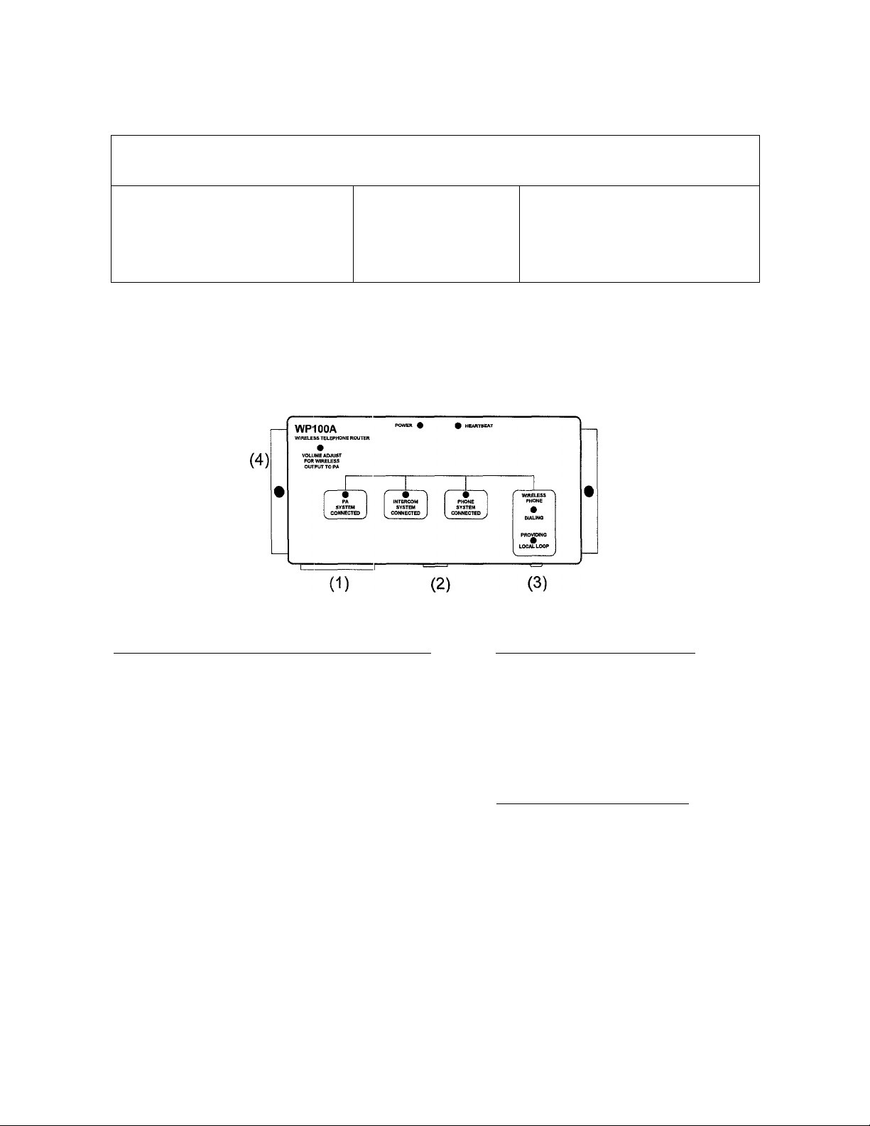
NAMES AND FUNCTIONS
1
WP100A
WP100A Wireless Telephone Router
ANA9500 900MHz Phone
Used with Aiphone’s
• MC-60/4A and MC-3 Market Com
• TD-H Selective Call Intercom ^
WP100A Wireless Intercom Interface “F?OAMER”
(1) 12-pin connector plug
(2) Phone cord input
(3) Power supply input
(4) Volume adjustment for PA input
DESCRIPTION:
The Wireless Intercom Interface (WP100A) allows a
900MHz cordless phone to work with Aiphone’s
intercom and paging systems:
• MC-60/4A and MC-60/4B
• MC-3
• TD-H or TD-Z
The cordless phone can make or receive an outside
phone call, initiate a page, or talk to someone on an
intercom station. The phone can also initiate or
respond to a call from the intercom station.
Aiphone Communication Systems
Equipment furnished with WP100A
1 - 24V AC Power supply
1 - 7’, 8-conductor phone cord
1 - RJ31X Phone jack
2 - Packet of screws and wire nuts
1 - 4.7K ohm resistor, 1/4W
1 - Installation manual
Uniden ANA9500 Cordless Phone
1 - Base Unit
1 - Handset
1 - 8’, 2-conductor phone cord
1 - 10V DC Power supply
2 - Rechargable batteries
1 - Belt clip
1 - RJ11 Telephone jack
2 - Operational guide (photocopy quantities)
Intercom Solutions for
Communications and Security
Page 2

9 FEATURES
• Full communications with the Telephone system, Intercom system, and Paging system.
• Place and receive outside phone calls
• Make a page through the overhead PA system
• Receive a call from any intercom station (ring or vibration from ANA9500)
• Place a call to an intercom station on a specified channel
• Compatibility with any 2500-set compatible cordless phone, or our specified
ANA9500 900MHz phone.
• Multiple cordless phones in a system, each with its own WP100A interface.
• Up to 2 cordless phones with MC-60/4A system
• Up to 4 cordless phones with the TD-H or TD-Z paging systems
• Compatible with MC-3, two-line system (Max. 1 cordless phone)
^ PRECAUTIONS
BEFORE YOU INSTALL OR OPERATE THE EQUIPMENT
Wireless Interface Adaptor:
1. Do not connect power supply to unit until all wiring connections are complete.
2. Select an Installation location that is accessible, and not exposed to temperature
extremes, moisture, or excessive dust.
3. The optimal place for installation is near the telephone and paging control
equipment.
Wireless Telephone Base Station:
1. In a standard sized facility where usage will be indoors, the base may be
installed near the telephone control equipment or in a Manager’s office.
2. In larger facilities, or where the wireless phone will be used outdoors, the base
station may need to be installed in a remote overhead location in the center of
the facility. If this is the case, an AC outlet must be nearby and a 2-conductor
phone cable must be run from the telephone equipment. When the base is
inaccessible to the user, the optional remote charging cradle (EXP9585) is
required.
A INSTALLATION
ADDITIONAL EQUIPMENT NEEDED FOR INSTALLATION:
• Standard telco interconnect too kit • Drill
• Tie wraps, tape, wire, hardware • Screwdriver set
1. Surface mount WP1OOA to wall or backboard with supplied screws. Unit should be
located near the telephone system and intercom/paging adaptor and amplifier.
AC outlet must be closeby to plug in 24V AC transformer.
2. Connect WP1 OOA to MC-A/A pagiing adaptor for intercom and PA functions. Wire
connections are made at 12-pin connector, which plugs into socket on WP100A.
Use 2 conductor shielded wire for paging output to MC-A/A. Use 3 conductor wire
to connect one intercom channel to WP100A (2 for power, 1 for communication).
Page 3

d INSTALLATION (Continued)
3. Plug 8 conductor phone cord between WP100A and RJ31X terminal block.
4. Connect a 1-pair cable (red/g reen) from the RJ31X terminal box to an analog port
on the telephone system.
5. Make a hardwire connection of 1-pair between the RJ31X and RJ11 terminal boxes.
(RJ31X white/blue to RJ11 red/green.)
6. From RJ11 terminal block, connect a 1-pair telephone cord with modular jack to the
“line in” port of the ANA9500 cordless phone base.
7. Plug 10V DC transformer into ANA9500 cordless phone base.
NOTE: See wiring diagrams for complete and detailed wiring information.
PHONE SYSTEM CONNECTION:
• The ANA9500 phone requires an analog port on the telephone system. Connect it to a
dedicated analog extension, or to a dedicated incoming line. If the phone system is digital,
the phone system provider should be contacted and asked to provide an analog port.
• If the cord from the WP100A to the RJ31X is unplugged, the cordless phone will still be
connected to the phone system, but will not have access to the intercom or PA system.
PAGING SYSTEM CONNECTION:
• Pins 1 and 2 of the WP100A should be connected to the highest priority input (600 ohm
balanced). If the amplifier has only one input and no muting circuit, a resistor (included in
accessory kit) must be installed. Refer to the amplifier’s instructions for actual connection
information, then choose the appropriate wiring diagram from this manual.
INTERCOM SYSTEM CONNECTION:
• The system can be configured to allow the intercom system to ring the cordless phone by
selecting channel 2 from the phone. Install jumpers as shown below on channels where
ring feature is required whenever a specific intercom channel is active. (MC-3 and MC-60/
4A only.) If the jumpers are not installed, the phone will still have communication with the
intercom, but the ringing function will be disabled.
Jumpers on: Rina channel
8 to 12
4 to 5, 9 to 12
4 to 6, 10 to 12
4 to 5, 5 to 6, 11 to 12
--------------------------------
--------------------------------
--------------------------------
-------------------------------------
>1
>2
>3
>4
TD-H SERIES SELECTIVE CALLING SYSTEM WITH WIRELESS ROAMER:
• The TD-H system can be interfaced with the Wireless Roamer for paging and intercom
functions.
- The TD-H stations can ring a cordless phone by being connected to a
station number, then pressing the station number and “CALL” on the TD-H phone.
The cordless phone will ring, and the person can answer by pressing “TALK”.
- The cordless phone can call to a person on a TD-H handset by being connected to
the TD-H’s “C” (call) terminal. To call, press TALK, the station number (1~4), and
the “#” key. The TD-H phone will ring, and when answered, begin speaking.
• Up to 4 WP100A interface units can be included in the TD-H system, each with its own
ANA9500 phone. This allows maximum flexibility for interfacing between the wireless and
hardwired communication systems.
Page 4

S TERMINAL FUNCTIONS and ADJUSTMENTS
The WP100A has a 24V AC transformer input, an 8-conductor modular phone jack input,
and a 12-pin terminal connector.
12-pin Connector Terminal Definitions:
The 12-pin connector can be connected to the system wiring while unplugged, then
simply plugged into the slot when wiring is completed.
1 Output to Amplifier (600 ohm balanced input)
2 Output to Amplifier (common)
3 Amplifier output shield (connect shield of 1 & 2 wires)
4 Common or negative
5 Call channel programing (For ring jumpers with MC system)
6 Call channel programing ( “ “ )
7 Call input ring terminal from TD-H system (TD-H system only)
8 Communication line 1 from intercom to phone
9 Communication line 2 from intercom to phone
10 Communication line 3 from intercom to phone
11 Communication line 4 from intercom to phone
12 Ring activation from intercom to cordless phone (MC system only)
VOLUME ADJUSTMENT:
• With a small screwdriver, the volume can be adjusted for the output volume of the page
from the ANA9500 phone. Additional volume adjustments for the paging system can be
done at the paging adaptor and amplifier.
PAGING ADAPTOR AND AMPLIFIER CONNECTIONS;
To connect the Wireless Roamer system to the paging system, use the 600 ohm balanced
input into the paging amplifier. This is usually noted as a “TEL” (telephone) input.
WP100A
--------
4
----------------
> MC-A/A
> 5/.
8~11 —> 3, 4, 6, 7 (For communication)
WP100A
--------
> Aiphoine PG-C series Amplifier
1 --------> 1 TEL (Set dip switches 1 &2to ON position)
2
-------
> 2 Common
3
-------
> 3 (Shield connection)
WP100A
---------
1
-------
2
-------
3
-------
> TOA 900 Series with L41S 600 ohm bal. muting module
> 3 (Hot)
> 2 (Common)
> 1 (Earth, Shield connection)
WP100A
--------
1
2
-------
3
-------
> Standard Paging Amplifier (Use muting input if music is included)
------
> 600 ohm balanced, HOT
> 600 ohm. Common
> Ground (Shield connection)
4
Page 5

fi WIRING DIAGRAMS
MC-60/4A WITH WIRELESS ROAMER SYSTEM
ANA9500 Phone Base
- With Aiphone PG-C Series Amplifier -
NOTES:
1. Lines 3 and 4 of the intercom are wired for
communication with the Roamer phone. The ring
jumpers allow the MC-60/4A to call the ANA9500
phone by selecting channel 4. Press "TALK" on
the phone to answer the call.
2. To call from the phone to the MC-60/4A system,
Press "TALK" and either “3” or "4".
3. Pretone will sound when paging from either the
MarketCom or ANA9500 phone when using the
PG-C series amplifier.
4. MC-60/4A handsets must be vi/ired in blocks with
maximum 10 stations per block.
PG-C DIP SWITCH SETTINGS:
* Before operating the system, be sure to configure
the dip switches as foilows:
1 & 2: ON (Upper position)
3: OFF (Lower position)
4 through 7: ON (Upper position)
8: OFF (Lower position)
Optional:
6 = Pretone on/off. If no pretone is desired, move
switch 6 to OFF position.
Page 6

fi WIRING DIAGRAMS
MC-60/4A WITH V\riRELESS ROAMER SYSTEM
ANA9500 Phone Base
- With MC-A/A and Amplifier -
IF P.A. AMP HAS ONLY 1 INPUT AVAILABLE
FOR PAGING
WP100A
NOTES:
1. All communication lines are shown wired to the
Roamer phone, allowing the phone to answer a
call on any intercom line. The ring jumpers allow
the MC-60/4A's to ring the ANA9500 by
selecting channel 4. Press "TALK" on the phone
to answer the call.
2. To call from the phone to the MC-60/4A system,
Press "TALK" and channel number (1 through 4).
3. MC-60/4A handsets must be wired in blocks
with maximum 10 stations per block.
Page 7

fi WIRING DIAGRAMS
MC-3 WITH WIRELESS ROAMER SYSTEM
ANA9500 Phone Base
- With MC-A and Amplifier -
IF P.A. AMP HAS ONLY 1 INPUT AVAILABLE
FOR PAGING
WP100A
NOTES:
Line 2 (green) is the designated intercom channel
1
for communication with the Roamer phone.
The ring jumpers aliow the MC-3's to ring the
ANA9500 phone by selecting channel 2. If both
intercom channeis are used regularly, It is
advised that the ring jumpers not be instalied.
2. To cail from the phone to the MC-3 system,
Press "TALK" and "2".
3. MC-3 handsets must be wired in blocks with
maximum 10 stations per block.
Page 8

WIRING DIAGRAMS
TD-H WITH WIRELESS ROAMER SYSTEM
ANA9500 Phone Base
- With PD-1 and Amplifier -
WHEN USING A PG-C SERIES AMP
PG-C Amp
PG-C DIP SWITCH SETTINGS:
* Before operating the system, be sure to
configure the dip switches as foilows:
1 through 8: OFF (Lower position)
Optional: 6 = Pretone on/off. If pretone is
desired, move switch to ON (Upper position).
IF P.A. AMP HAS ONLY 1 INPUT AVAILABLE
FOR PAGING
WP100A
NOTES:
1. In this example;
Channel 5 of TD-6H/B calls the Roamer phone.
Channel 6 of TD-6H/B accesses the paging system.
2. To call from the phone to a TD-H intercom, Press "TALK",
channel number (1 through 4) and press # to activate ringer.
3. To cali from a TD-6H/B to the Roamer phone, press "5" and
"CALL" on the TD-6H/B (in this example). To answer, press
"TALK" on the ANA9500.
Page 9

7 OPERATIONS
The WP100A Reamer System connects the ANA9500 cordless phone to the paging and
intercom system, as well as to the facility’s telephone system. The cordless phone allows
full roaming capabilities for the manager or person most needing to be in communication
with people both inside and outside the building.
TELEPHONE SYSTEM:
The WP100A connects the ANA9500 to the telephone, paging, and intercom systems. The
WP100A has three inputs to provide major functions.
1. When a hardwired extension in the phone system calls the ANA9500: Connected
through an analog port on the telephone system, a ring signal is sent to the WP100A.
• If the cordless phone is not busy, it will ring. There are three settings for ring: loud,
soft, and vibration. When the TALK button is pressed, the phone goes “off hook”
and is connected to the incoming call.
• If the ANA9500 is busy with an intercom call, both the cordless phone and
intercom will hear a call-waiting tone. The standard telephone placing the call
will hear a ring-back tone.
2. When an intercom station calls the ANA9500: The ring jumper(s) must be installed on
the WP100A to allow the MarketCom system to ring the cordless phone. (See pg. 3)
• The person at the intercom picks up the handset and selects the designated
channel button.
• If the ANA9500 is not busy, it will ring. When the TALK button is pressed, the
cordless phone is connected to the designated channel on the intercom system.
• If the cordless phone is busy with a standard telephone call, a busy tone will be
heard at the calling party’s intercom.
• If the ANA9500 is busy with an intercom call, both the cordless phone and
Intercom will hear a call-waiting tone.
3. Placing a call from the ANA9500 cordless phone: If no other call is waiting, a go-ahead
tone will be heard when the TALK button is pressed.
• To connect to a standard telephone extension, press “TALK, *”.
• To page, press “TALK, 0”, wait for pretone, then make a page announcement.
• To connect to an intercom channel, press TALK and designated communication
channel (1~4).
• With the TD-H system, the ANA9500 can ring a TD-H phone if wired to do so.
ADVISORY TONES:
During normal operation, the WP100A generates the following advisory tones:
• Go Ahead. Series of three tones sent when the ANA9500 goes off-hook and
there are no calls waiting.
• Paging. Series of five tones sent after the ANA9500 has dialed “0” to access the
PA system, and indicates that a page can now be made.
• Paging Pre-tone. Tone sent over the PA system to indicate that a page is
forthcoming. When using Aiphone’s PG-C series amplifier, the same pretone will be
heard when paging from the intercom or cordless phone, with adjustable volume.
Page 10

7 OPERATIONS
_________________________________________________
ADVISORY TONES (Continued):
• Call Waiting. Tone sent to the ANA9500 and the intercom station connected
to it to indicate that another telephone or intercom is trying to call the cordless
phone.
• Ring-back. Tone sent to an intercom that is attempting to call the ANA9500.
This tone is heard on the intercom station to indicate that the cordless phone is
ringing.
• Busy. Tone sent to an intercom that is attempting to call the cordless phone when
it is already on a call through the standard telephone system.
ft TROUBLESHOOTING
SYSTEM STATUS LED INDICATORS:
Name;
Power
Heartbeat
PA System Connected
Intercom System Connected
Phone System Connected
Dialing
Providing Local Loop
Function:
• Illuminates when power is on
• Fiash(;s during normal operation
• Illuminates when ANA9500 is connected to PA
• Flash(5S for an incoming call, stays lit when the ANA9500
is connected to an intercom station
• Flash(;s for an incoming call, stays lit when the ANA9500
is accessing an outside phone line (or other phone extension)
• Flashes when digits are being pressed on ANA9500
• Illuminates when local loop is provided to the ANA9500 phone
FAULT TOLERANCE:
• If the WP100A loses power, internal jumpers in the WP100A connect the cordless phone
to the facility’s phone system. If the 8-conductor phone cord is unplugged, internal jumpers
will connect the ANA9500 phone to the phone system. This ensures that in power outages
or system tampering that the cordless phone will still have primary telephone functions.
REMOVAL OF WP100A:
If the WP100A Interface unit needs to be taken out of the system for any reason, unplug
the phone cord at the RJ31X terminal block. This will ensure that the cordless phone will
still be connected to the telephone system (through internal jumpers in the RJ31X).
10
Page 11

ft TROUBLESHOOTING (Continued)
After the WP100A has been installed, no routine maintenance is required. Problems with
the system are easily identified by observing the LED status indicators.
PROBLEM:
Power LED
not illuminated
Heartbeat LED
stopped flashing
ANA9500 phone
does not receive
or send
CORRECTIVE ACTION:
Check that the power supply and cable are plugged in properly and
firmly. Verify that the AC outlet is live.
If the heartbeat LED has stopped flashing (remaining steady or not lit
at all), unplug the power supply for 10 seconds, then plug back in.
1. Unplug the 8-conductor cable from the RJ31X block
connector (not fiom the WP100A) and verify that the ANA9500
can access the facility’s phone system.
2. If the ANA9500 can’t access the phone system, unplug the
ANA9500 and rejplace it with a standard analog telephone (2500
set). The 2500 set is for testing only; it cannot be rung by the
WP100A. Verify that the test phone can access the facility’s phone
system. If it does work, then the ANA9500 may be faulty, or a portion
of the phone system or cabling may be defective.
ADDITIONAL TROUBLESHOOTINC5 FOR ANA9500:
Problem:
Charge light
doesn’t come on
Corrective Action:
• Make sure AC adaptor is plugged into the base unit and AC outlet.
• Make sure handset is properly seated in base unit.
• Make sure NiCad battery is properly placed on the handset.
• Make sure the charging contacts on the handset and base are clean.
Conversation
interrupted
frequently
Warning tone &
NO SERVICE
message
Handset doesn’t
ring.
• Make sure the base unit antenna is fully vertical.
• Move closer to the base unit while communicating, or relocate the
base unit to a more central location.
• Check for LOW BAT warning.
• Move closer to the base unit.
• Make sure ring jumpers are installed properly.
• Ni-Cad battery may be weak. Charge the battery for 8-10 hours.
• Check the Ringer Alert setting, which may be on “RING OFF” mode.
• Make sure the base unit antenna is fully vertical.
• The handset may be too far away from the base unit.
11
Page 12

Ç> SPECIFICATIONS
WP100A WIRELESS TELEPHONE RO UTER:
Power:
Phone Output:
PA Output:
Dimensions:
24V AC. Use AC adaptor provided.
Analog port
600 ohm balanced
5-9/16”H X 10-3/16”W X 1-3/8”D (Width includes mounting flanges.)
ANA9500 900MHz CORDLESS PHONE:
Power: 10V DC
Frequency Control: Phase Lock Loop
Modulation:
Operating T emp:
MSK
10 to 130 degrees
Base Unit:
Trans/Rec Freq:
Dimensions:
Weight:
902MHz - 928 MHz Spread Spectrum
7-3/4”H X 3-1/8”W >: 7/8”D
Approx. 1 lb. 5 oz.
Handset:
Power:
Dimensions:
Weight:
Battery:
Rechargeable Ni-Cad battery pack
6-1/2”H x2-1/8”W X 7/8”D
Approx. 8.6 oz. witfi battery
Capacity: 400 mAH, 4.8V
Talk Mode: 3 hours (typical)
Standby Mode: 42 hours (typical)
Specifications are subject to change without notice.
Aiphone Communication Systems
1700 130th Ave. N.E.
Bellevue, WA 98005
(425) 455-0510
FAX (425) 455-0071
Toll Free Technical Support
(800) 692-0200
FAX (800) 832-3765
12
Intercom Solutions for
Communications and Security
 Loading...