

Page 1
83154100 0595
C AlPHONE
VY Series
PanTilt VIDEO ENTRANCE CALL SYSTEM
Models:
VY-10EM (10-call)
INSTALLATION & OPERATION MANUAL
CONTENTS
1 SYSTEM OUTLINE & COMPONENTS........................................................................................................1
2 NAMES & FEATURES..................................................................................................................................2
3 PRECAUTIOS ON INSTALLATION & WIRING............................................................................................3
4 WIRING..................................................................................................................................................4 ~ 10
5 MOUNTING............................................................................................................................................11 ~ 12
6 OPERATIONS on VY-EM AND MY....................................................................................................13-14
7 TECHNICAL PRECAUTIONS.....................................................................................................................15
8 SPECIFICATIONS......................................................................................................................................16
1
SYSTEM OUTLrNE AND COMPONENTS
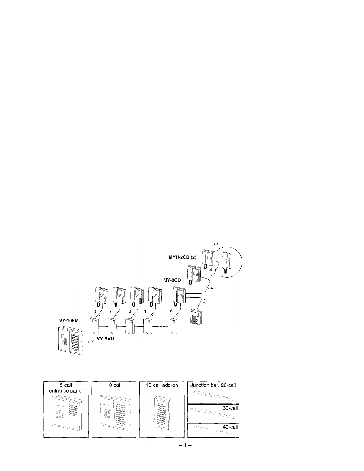
■ System outline
The VY-EM Series is a 5- or 10-call PanTilt entrance-call panels. Residential monitor
MY-1CD or MY-2CD may be installed in conjunction with VY-RVU adaptors.
MY-1HD
MY-1CD
Package contents
5-, 10-call entrance panel
(VY-5EM, VY-10EM)
Back box
Packet of screws
Tamper-proof screwdriver
Directory card
Directory opener
Installation & Operation Manual
3 pairs 5 pairs
for indiv. call,
separate sheathed
MY-DS
wide-angle,
surface
Components available
VY-5EM VY-10EWI
VY-10U
VYK-A20, 30, 40
VY-RVU PS-24N
Residential
adaptor
Power supply
Page 2
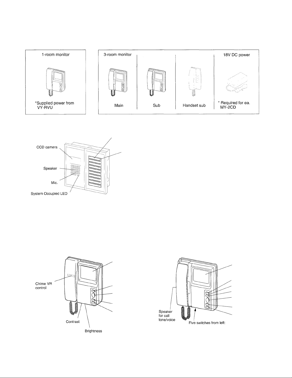
Components available
• Residential monitor
MY-1CD
NAMES AND FEATURES
VY-10EM
MY-2CD
Residence directory
Residence call
button
MYH-2CD
MY-1HD
PS-18D/18C
VY-EM consists of CCD camera / intercom
& 5 or 10 direct call key entrance panels.
One to three VY-10U add-on panels can be
united with junction bar VYK-A20~40, and
mounted on back boxes assembled.
Surface-mount box (B-VY10) is available
for VY-5/10EM.
Features
* PanTilt Video Entrance-Call system, 5 to max. 40-call
* 1 to max. 3 video entries
* 3-pair trunkage, VY-RVU adaptor to adaptor and individual call wires separately jacketed
* Choice of MY-1CD single-room or MY-2CD 3-room monitor
* Communication secrecy, single-channel
* Door release system
MY-1CD
video monitor
(4" CRT)
Door release
PanTilt control
pad
Backlight
control
Monitor
No separate power supply required
MY-2CD
* Reset, SWI, contrast, brightness &
call tone volume
★ See page 9 for SW1 setting.
Residential door station, PanTilt or wide-angle MY
or lE/IF audio
Sub monitor(s) MYH-2CD or sub handset(s) MY-1 HD
Video monitor
(4" CRT)
. Door release
- Call annunciator LED
' All room call
' PanTilt control pad
Backlight control
Monitor
Page 3

I PRECAUTIONS ON INSTALLATION & WIRING ---------------------------------------------
A CAUTION
if Do not connect any terminal on any unit to AC power lines to prevent fire or unit damage.
★ High voltage is present on the monitor unit inside. Do not open MY room monitor without first
unplugging the power supply, to prevent electric shock.
if Do not attempt to install or connect wires on VY-EM nor MY equipment while system’s power
supply is plugged in.
★ MY monitors and related equipment, except door station, are designed for indoor use only. Do not
install outdoors.
★ Do not connect any other power supply than specified on +, - on VY-EM and MY monitor. Doing so
can damage the equipment.
IMPORTANT
★ For system’s installation, there is no need to disassemble the equipment. Do not open any VY-EM
system components unless properly qualified.
★ Any other manufacturer’s products installed with this system (door release, external signalling device,
etc.) are not covered under Aiphone’s warranty.
★ Do not mount VY and MY equipment in the following places, as it may cause the system to malfunction:
• High or extreme cold temperature areas: under direct sunlight, near equipment that varies in
temperature, in front of air-conditioner, inside a refrigerated area, etc.
• Places subject to moisture or humidity extremes.
• Places subject to environmental conditions, such as dust, oil, chemicals, etc.
★ VY/MY are an electrical devices, which must not be subjected to water, or any other liquid.
★ Weather conditions, such as lightning storms, may cause damage to VY-EM equipment. We
recommend that power surge protection be installed as follows: (However, this does not guarantee
that no damage will occur).
> If the power supply has a GROUND terminal, take it to an earth ground.
In this case, a separate surge arrester is not necessary.
Before actually installing the VY-EM & MY system, the contents on pages 4-12 must be thoroughly read and understood.
-3-
Page 4
WIRING
--------------
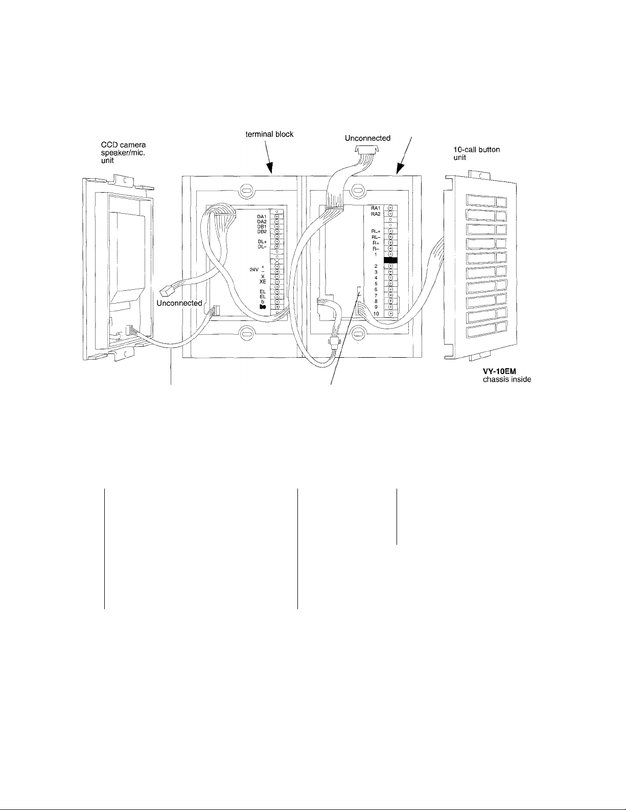
I Terminal block layout
6P connector
VY-EM
Impedance-matching
connector
Trunk line
to VY-RVUs
• For
wiring to VY
, DA2 : Video signal
DAI
EM entrance panels
DB1 , DB2 : Video signal
, DL- : Door release control
DL+
-1-
X , XE
EL
b
, - :
, EL
, be
(for 2-3 VY-EM's)
Power supply (DC24V)
system control
(for 2-3 VY-EM's)
Door release connection
lllumination/light control
Laying out the system
• Cable
Use twisted pair cable 1.0-1.2mm dia., 18 - 16AWG for trunkage line. If it contains extra pairs,
those must be terminated with a 120 Q resistor at both ends. As to individual call wires, use the
same but separately jacketed twisted pair cable, in which unused pairs may remain unterminated
-4-
• For wiring to residential VY-RVU's
RA1 , RA2 : Video signal
RL+ , RL- : Door release control
R+ , R- : Power supply
1 - 10 :
★ VY-10U add-on panel has the same terminal block,
allowing to run another trunk cable.
Individual calling,
separately sheathed
Page 5
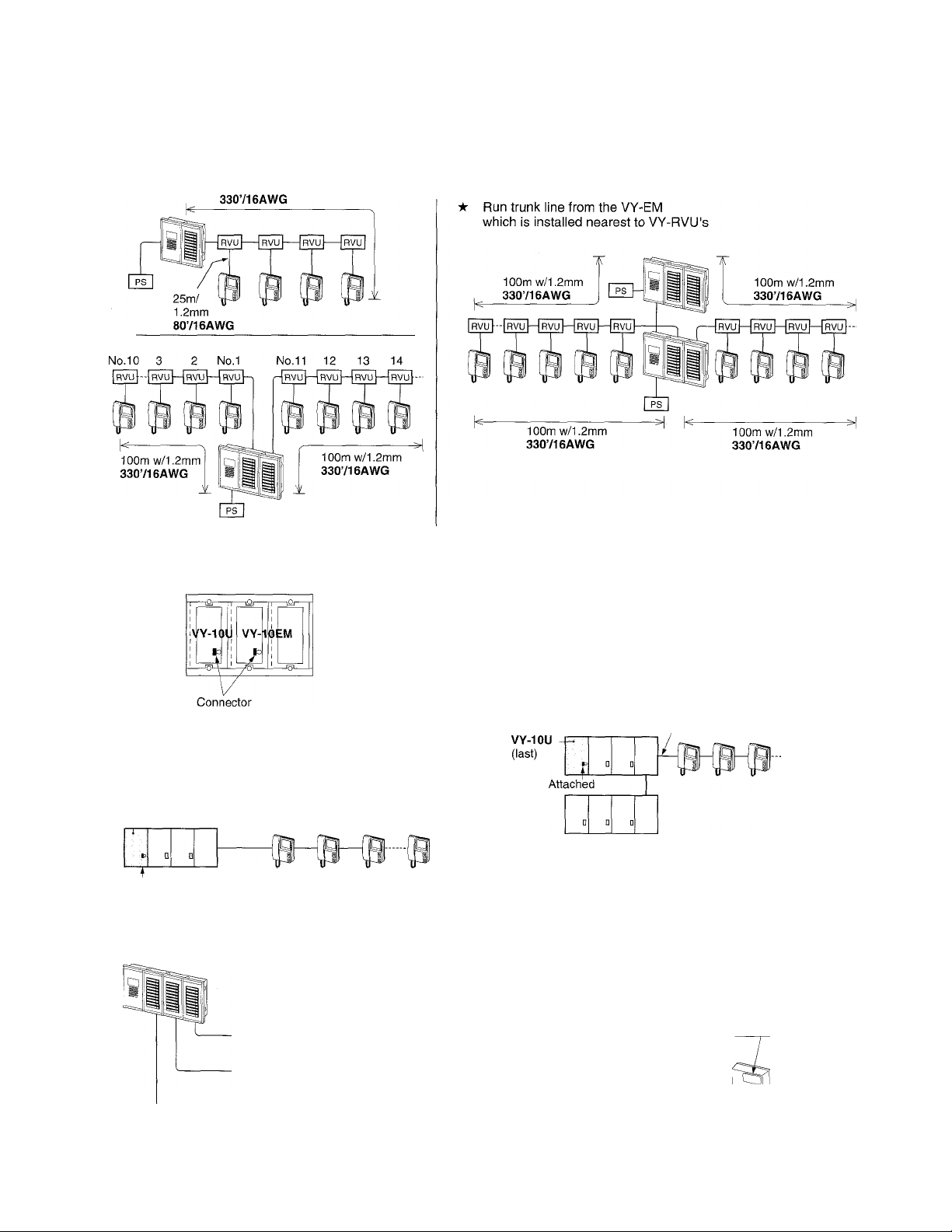
• Trunkage
VY-EM system may have one or multiple trunk cable run to VY-RVU residential
adaptors, each trunk installing any number of VY-RVU's as required.
VY-10U has the same terminal block as on VY-EM, allowing to start another trunk
cable run.
10Om w/1.2mm
• Impedance-matching on VY-EMAAY-10U
VY-10EM
Attached
VY-10U (last)
Attached
• Impedance-matching on VY-RVU
VY-EM
Set all sw. to
ON position.
VY-RVU
VY-EM & VY-10U add-on are equipped with
terminating connector.
When system has more than one VY-EM
paneis and with VY-10U, plug off at all those
panels, except on the last VY-EM or VY-10U
from which trunk cable is run.
Trunk
On the last VY-RVU adaptor on a trunk
cable(s), set the 4 switches to all
upper ON position.
BBsat
•5-
VY-RVU
Page 6

Wiring to door release (on each VY-EM)
VY-EM entrance call panel provides
dry contact closure for door release.
VY-10EWI
EL-9S
z:
12V AC,
0.35A
Q □
AC transformer
PT-1210N
^ Door release of other manufacture
can be used in conjunction with Aiphone’s
MAW-B relay, powered by VY-EM’s PS-24N.
VY-10EM
EL
EL
Lighting control at VY-EM entrance
VY-EM panel also provides
dry contact closure for
illuminating incandescent
lamps for general lighting of
less than 10OW.
It turns on when the VY-EM
placed a call, activating the
room monitor.
VY-10EM
Page 7

Trunkage wiring
Trunkage
VY-10EM
For 20~40-call entrance panels,
1. Unite VY-EM and VY-10U(s) each with plug-in connectors,
except on the last VY-10U, (See page 12.)
2. Remove all impedance-matching connectors, except on the
last VY-10U. (See page 5.)
3. VY-10U is equipped with the same terminal block layout as
per diagram below. Run a 2nd trunk cable and max. 5-twisted
pair cable, separately sheathed.
VY
VY-10EM
&
Q
iS
-
SI
VY-RVU
NEVER
I to next
a I VY-RVU's
D0(_^
to VY-10EM
VY-RVU
J
3P
V y
y X
B
VY-RVU
VY-RVU
* Run 3-twisted pair cable to
VY-RVU's without reconnections.
* As to direct-key 1 ~ 10-call wire,
run max. 5-twisted pair,
separately sheathed.
* Observe pairing terminals as shown
above.
* Secure 100m/ji 1.0 (330718AWG) with
reinforced wires on R+, R-.
I Wiring distance
VY-EM ~ Residential monitor (farthest)
Diam. 1.0mm
Distance
AWG
Distance
80m
18AWG
260'
VY-EM ~ PS-24N
Diameter
Distance 10m
AWG
Distance
■7-
1.2mm
16AWG 14AWG
35' 65'
1.2mm
100m
16AWG
330'
1.6mm
20m
Page 8

VY-EM more than 100m (330’) application
When VY-EM has distant installation of a VY-RVU area more
than 100 ~ 300m (330’ ~ 980’) away, use an MYW-BA and a
specified 1-pair video cable out of 3-pair trunk. A PS-24N is
additionally required for the VY-RVU’s.
VY-EM
MYW-BA VY-RVU
- A1 B1 -
A2
One pair for video, specified
Specified
B2 -
tuc
PS-24N
RA1
RA2
RL+
RL-
R+
R-
Specified
&
:zn
West Penn D990 (in USA) or equivalent
• Impedance: 90ohm
• Permitted closed loop DC resistance: 9.9
ohm or less
• Non-PVC insulation
plus 2 pairs (R+ unconnected), separarately
sheathed.
: PS-18YC or PS-18C.
PS-18YD or PS-18D
Residential monitor MY-ICD
to next VY-RVYU
Run 6-conductor cable, twisted or
non-twisted to MY-ICD.
Take SG terminal to earth, which
may help to eliminate noise from
+, - lines.
VY-RVU
I Wiring distance
VY-RVU ~ Residential monitor
Diameter 1.0mm
Distance 20m 25m
AWG 18AWG
Distance
★ The distance is doubled with reinforced wires on
65'
MY-ICD
1.2mm
16AWG
80'
•8-
Page 9

Residential monitor MY-2CD
to next VY-RVYU
VY-RVU
MYH-2CD
в
ÍLjÍ[
MYH-2CD
о
* Run 6 conductor cable twisted or
non-twisted to MY-2CD.
* Residential door station can be
either PanTilt, wide-angle or audio
only.
* Take G terminal to earth on
PS-18D (18C), which may help to
eliminate noise from +, - lines.
* Connect A1, A2 on VY-RVU to
4-tone chime receive terminals
1A1,1A2on MY-2CD.
SW1 setting
MY-2CD
1 station
2 station
3 station
(*) MY-2CD B : VY system.
(**) MYH-2CD A : Terminated, B : high-impedance
В - -
В
ВГ)
I Wiring distance
VY-RVU ~ Residential monitor
Diameter
Distance 20m
AWG
Distance 65'
★ The distance is doubled with reinforced wires on
+ , -■
1.0mm
18AWG 16AWG
-9-
MYH-2CD
or MY-1HD
A
В A(* **)
1.2mm
25m
80'
MYH-2CD
or MY-1HD
-
Page 10

2 ~ 3 Entrance Call Panels
VY-10EM VY-10EM VY-10EM
1
Si
To VY-RVU
PS-24N
n
X X
X X
1 )^
_ _ _
----------
—►
-------►
►
Trunkage
Each call
receive C
terminal
★ The distance between VY-EM(any) and farthest monitor MY-1CD
or MY-2CD should not exceed 100m with 1.2mm dia. (330' w/IOAWG).
- 10-
Page 11

MOUNTING
Mounting location
VY-EM entrance call panel employs CCD camera with
infrared LEDs, and its performance can be affected with
the environmental lighting conditions.
For best results, observe the followings:
1. Decide the height of camera, referring to the image
viewing area, as shown right.
2. VY-EM panel does not face light-emitting sources or
direct sunlight, coming directly into camera lens.
3. VY-EM panel, while holding weather-resistency, should
not be exposed to direct rain, etc. (Protection with hood,
etc. should be considered).
Mounting VY-5EM or VY-10EM panel
VY-EM consists of 3 components: front panels, chassis &
back box. VY-EM panel flush-mounts on back box in the
wall.
Pan/tilt viewing area
shown by dotted line
1 34cm (13")
72cm (29")
34cm (13") 1
- 50cm
■ (20")
Viewing area of camera
remaining in still position.
Back box VY-5EM, VY-10EM is measured
(H X Wx D):
240 X 250 X 62 (mm)
9-7/16" X 9-7/8" X 2-7/16"
★ The hole should have a space of at least
3mm, 1/8" on both sides.
1. Disassemble 2 front panels, unscrewing 4 tamper screws on the panel frames.
2. Disconnect front panels, unplugging connectors from the chassis.
3. Mount the chassis on back box at 4 points, (screws are supplied)
4. Make wire terminations on the terminal block according to the wire color codes prearranged.
★ Plug off matching connector on all middle call button panels.
5. Reconnect front panels, and remount to the chassis.
■ VY-RVU residential adaptor
VY-RVU can be mounted with 83.5mm, 3-5/16" guide. The adaptor operates with its housing getting
warm, which is a normal occurrence.
^ When running intercom cables, maintain a distance of at least 2 feet (60cm) from any AC
wiring, fluorescent lighting, and dimmer switches.
-11 -
Page 12

Assembling VY-10U (1 ~ 3) panels to VY-EM
VY-5EM or VY-10EM with VY-10U panel(s), are
made up for 15 to max. 40-call entrance panel.
Back box dimensions
VY station
VY-5EM, VY-10EM
VY-10EM + 1 VY-10U
20-call
VY-10EM-t-2VY-10U
30-call
VY-10EM-h3VY-10U
40-call
High
240 mm
10 feet
Wide Deep
250 mm
10 feet
390 mm
16 feet
530 mm
21 feet
670 mm
27 feet
62 mm
3 feet
1. Loosen screws (7) on back of VY-5/1 OEM chassis.
2. Attach new junction bar (2) VYK-A20 ~ 40, aligning
on the ditch.
Fasten all screws, on VYK-A plate to unite.
3. On back boxes, before assembly, knock out a hole
on each facing side. Attach VY-10U box to VY-EM's
with 2 screws top and bottom.
4. Detach panel frames, using special screwdriver.
5. Loosen panel-fixing screws (6-10) and disconnect
VY-EMA/Y-IOU's to separate from chassis.
6. Mount the chassis (assembled) to back box.
7. Reconnect and mount VY-EM/VY-10U panels on
the chassis.
1 Loosen
Ditch
Junction
bar
VY-10EM
back view
VYK-A20
__
4. Detach
- 12-
Ditch
^ ii ii ii
VYK-A20, adjustable
Page 13

6 OPERATIONS on VY-EM and MY
■ On VY-EM entrance-call panel
Momentarily press a residence call
button.
•k The channel to VY-EM can be resumed with 5-sec. time-out timer in any operation.
On MY-1CD residential monitor
Chime, 4-tone is activated.
Video monitor is turned on
with image.
Pick up handset, and
communicate.
On MY-2CD residential monitor
When a room station replies, speak to
the mic, standing in front of panel
(within 50cm, 20").
Hang up handset.
The monitor is turned off.
When call button is pressed, 4-tone chime sounds,
and all monitors are turned on with image.
Pan/tiit viewing
While the image is
alive on the monitor,
operate pan-and-tilting
the VY-EM camera
pressing the edge of
diamond-shaped pad.
The VY-EM camera
returns to initial
position, after hanging
up handset.
-13-
Pick up (any) handset,
and communicate.
The monitor is turned off
upon hanging up.
image viewing area
-180cm, 72"
Page 14
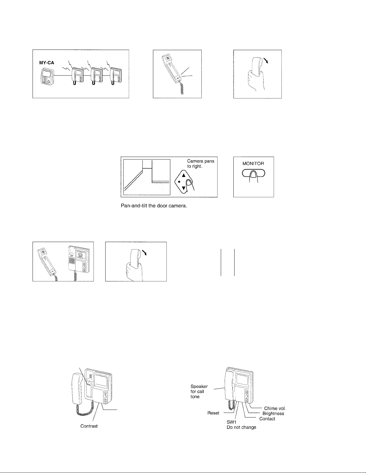
MY-2CD system - Operates indepently from VY-EM
■ Receiving a cail from residentiai MY-CA
Chime sounds in 2-tone, activating all
monitors with image.
★ If the monitor is turned off, press Monitor button once to restore.
Pick up (any) handset,
and communicate.
■ Pan/tilt monitoring of MY-CA
MONITOR
Cpp
Once
Any time
Press once Monitor button.
Image of MY-CA comes on.
Receiving a caii from VY-EM during communication
\|
Hang up, and the monitor is
turned off.
Press Monitor to turn off.
11 '
Monitor is turned on with
chime tone.
★ VY-EM call-in is held for approx. 10 seconds, while MY-2CD is communicating.
Hang up handset at both to Repick up handset at answering
conclude. station.
Adjustments
MY-1CD
Chime voi.
Brightness
- 14-
MY-2CD
Page 15

TECHNICAL PRECAUTIONS
(System In-use LED)
(Incorrect calling)
(Video monitoring)
(Call-in timer)
(Communication timer)
(Door release)
★ When system has more than one VY-EM entrance-call panels, see,
before use, the Occupied LED is not lit. It invalidates a call.
★ When a call button of another suite, is pressed during communication, it
disconnects the line present, and rings that station. On the VY-EM panel,
see the Occupied LED goes off, and the initial suite station can be called
again.
★ MY-1CD or MY-2CD residential monitors are not capable of monitoring
VY-EM. Only when called, pan-and-tilting VY camera is operable.
★ On MY-2CD system only, MY-CA camera (and MY-DS wide-angle) can be
activated for monitoring and pan/tilt scanning its entry.
★ 45 seconds for call-in from VY-EM (With 5 sec. time-out timer)
★ 2-1/2 minutes for room-to-VY-EM (MY-CA) communication.
(With 5 sec. time-out timer) To resume, press MONITOR button while
communicating. Repick up if handset is placed.
★ When key-marked button is held down, the white line may appear on the
monitor, which is a temporal occurrence.
Terminating the unused pairs in trunk cable
★ Unused pairs in the trunk cable,
must be terminated by a 120
.ohm resistor at both ends for
clearer video transmit lines.
(Operating temperature)
Cleaning the VY-EM equipment
★ Clean VY-EM and MY-1CD/MY-2CD with a soft and dry cloth.
When the soil is not easily cleaned, the cloth may be dampened with neutral household cleanser.
Never use any abrasive cleaner or cloth.
★ Keep direct forceful rain or water away from the front of VY-EM, is spite that the units are designed
★ The VY-EM is rated to operate at temperatures between -10°C and 60°C
(14°F and 140°F). When the outside temperature lowers rapidly, the lens
may fog up slightly, causing a blurry picture at the inside monitor. The
ventilation openings will allow the moisture to evaporate, and the picture
will return to normal.
Reconnect
-15-
Page 16

8 SPECIFICATIONS
VY-EM
* Power source
* Current consumption:
Max.
Standby
Station capacity
Camera unit
Scanning iine
Type of monitor
Calling
Communication
Door release system
Wiring & distance
VY-EM to residence area (VY-RVU‘s) 3 pairs + 1 / resid. 80 m
Between VY-EM's
VY-RVU to MY-1CD or MY-2CD 6 cond. (parallei) 20m
★ See pages 5 ~ 11 wiring section for each system configuration.
Dimensions (H x W x D) & weight
24V DC. Install a PS-24N power supply at each VY-EM.
VY-EM 2nd or 3rd VY
1.4A 0.19A
0.15A 0.15A
VY-10U
0.075A
OA
1-3 YY-EM entrance call stations
1-3 VY-10U add-on panels, 10-cali
5-40 MY-1CD and/or MY-2CD residential monitors
CCD camera, with infrared LEDs
525 lines
MY-1CD or MY-2CD w/PanTilt pad
Electronic chime, 4 or 2-tone (from resid. door)
Single-channel, non-open communication
VY-EM has EL,EL dry-contact closure for door strike
(Capacity: Max. AC 24V, 50mA. Max. DC 24V, 250mA).
Activation by key-mark button on communicating MY monitor
Use twisted pair cable for trunk
1.0mm
3 pairs + 1 / resid. Within the specified distance
★ The distance VY-RVU to monitor is doubled
with reinforced wires on +, -.
18AWG
260'
65'
1.2mm
100m
25m
16AWG
330'
80'
VY-5EM, VY-10EM
VY-10U
VY-RVU 140 X 74 X 42 (mm).
This equipment has been tested and found to comply with the limits for a Class B digital device, pursuant to Part 15 of the FCC Rules. These
limits are designed to provide reasonable protection against harmful interference in a residential installation. This equipment generates,
uses, and can radiate radio frequency energy and, if not installed and used in accordance with the instructions, may cause harmful
Interference to radio communications. However, there is no guarantee that interference will not occur In a particular installation. If this
equipment does cause harmful inteference to radio or television reception, which can be determined by turning the equipment off and on, the
user is encouraged to try to correct the interference by one or more of the following measures:
• Reorient or relocate the receiving antenna. • Connect the equipment into an outlet on a circuit different from that to which the receiver is
connected. • Increase the separation between the equipment and receiver. • Consult the dealer or an experienced radio/TV technician
for help.
-t-
Aiphone warrants its products to be free from defects of material and workmanship under normal use and service for a period of two
years after delivery to the ultimate user and will repair free of charge or replace at no charge, should it become defective upon which
-sexamination shall disclose to be defective and under warranty. Aiphone reserves unto itself the sole right to make the final decision
whether there is a defect in materials and/or workmanship; and whether or not the product is within the warranty.
This warranty shall not apply to any Aiphone product which has been subject to misuse, neglect, accident, or to use in violation of
instructions furnished, nor extended to units which have been repaired or altered outside of the factory. This warranty does not cover
batteries or damage caused by batteries used in connection with the product.
This warranty covers bench repairs only, and any repairs must be made at the shop or place designated in writing by Aiphone.
Aiphone will not be responsible for any costs incurred involving on site service calls.
•i*
280 X 290 X 90.2 (mm).
11" x11-1/2" X 3-3/4".
280 X 140x90.2 (mm).
11"x 5-1/2” X 3-3/4".
5-1/2" x3" X 1-1/2".
WARRANTY
62 recessed.
2-1/2" recessed
62 recessed.
2-1/2" recessed
2.0Kg. (4.41 lbs.)
0.8Kg.(1.76 lbs.)
0.25Kg.(0.60 lbs.)
•i*
•i*
•i*
•f*
-i*
Aiphone Co., Ltd., Nagoya, Japan
Aiphone Corporation, Bellevue, WA, USA
VY-EM-I(E) 0595J
-16-
COMMUNICATION SYSTEMS
® AIPHONE
HOME, BUSINESS, INDUSTRY.
Printed in Japan (E)
 Loading...