

Page 1
0894©
o AIPHONE
APARTMENT HOUSE INTERCOM SYSTEM
MODELS;
INSTRUCTIONS
VC-K
VC-OM. VC- 1M, VC-2M
VC-4M. VC-6M. VC-8M
VC- 10M
VCH-8,VCH-16
VC-26MY. VC-42MY
VC-26MT, VC-58MT
(Apartment station)
(Entrance station, 0-/1-/2-call)
(Entrance station, 4-/6-/8-call)
(Entrance station, 10-call)
(Add-on call button panel, 8-/16-call)
(One-paneled entrance station,
horizontal type, 26-/42-call)
(— do —, vertical type, 26-/58-call)
Screws for VC-K;
NA
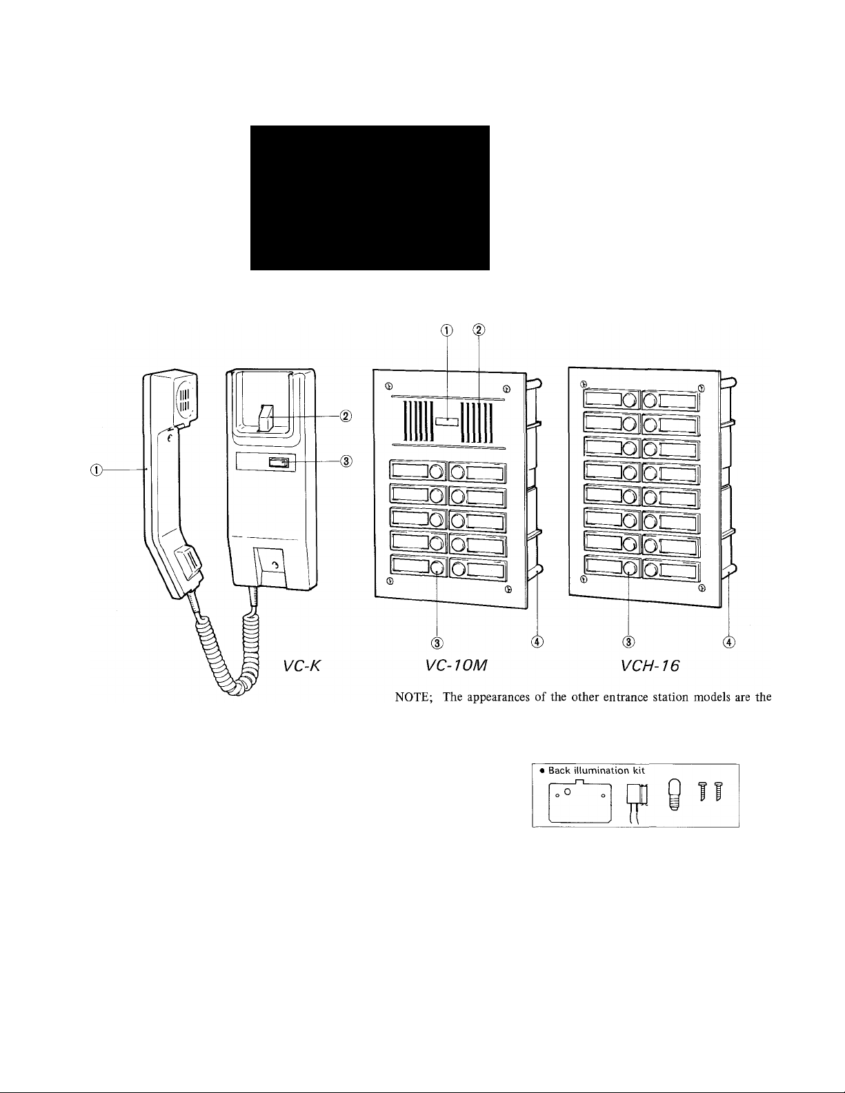
NAMES AND FUNCTIONS
VC-K;
© Handset
@ Hook knob
® Door release button
same as VC-IOM or VCH-16, except the number of call buttons.
Screws, washers and directory illumination kit for VC-nM & VCH;
® © ® ®
VC-IOM, VCH-16;
(VCH-16 has two sets).
© AIPHONE mark
® Speaker/mic unit
® Call button with directory
© Back box
- 1
Page 2
SYSTEM FEATURES
* Loop-wiring system by 4 common plus 1 individual wires per station (3 + 1, if door release is not required).
* Maximum two VC-K stations per apartment.
* Seven entrance station models with 8- or 16-call add-on panels to meet small to larger apartments.
* Directory card back illumination.
* One-paneled entrance stations available, either vertical or horizontal type.
* VC-BBX surface-mount back box for VC-nM & VCH panels.
VC-26MY
VC-26MT
Oi^
ofoc
^iOr
VC-42MY
ZDC'iO^ ^OllOl 1
!1
i::]oion
l!
iDoloc:
LJOIIOLZ
|l
^OllOd
-451 mm (17-3/4"
-492 mm (19-3/8"
^1 iL
l| 1
l| l!
11 11
ll II
VC-58MT
“]OlOI 1
~i01!0l i
LJOIOI 1
LJOlOl 1
^□OllOl 1
UOIIOI !
^OIIOI .i
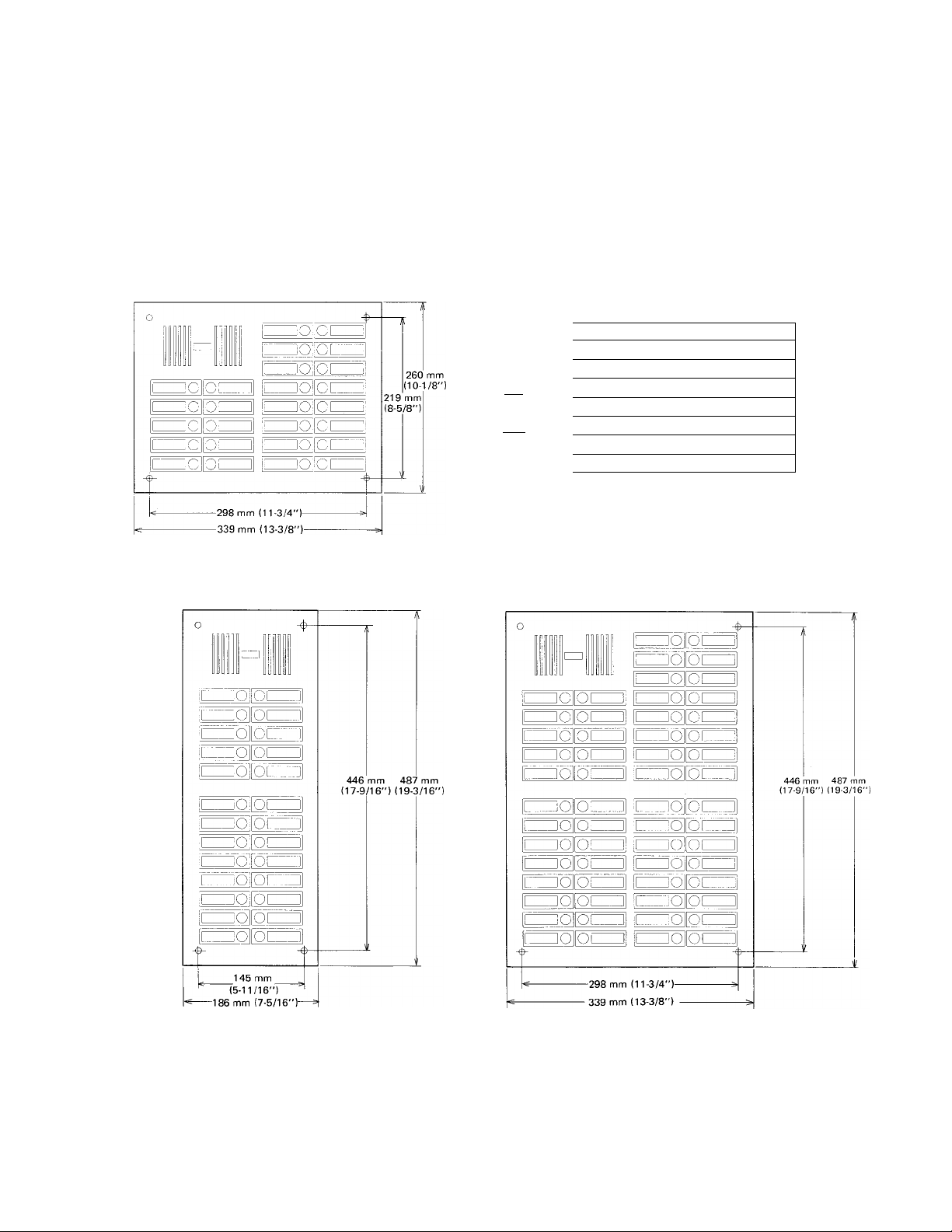
(10-1/8”)
219 mm
(8-5/8”
260 mm
NOTES; The above drawings illustrate a full compliment of call buttons mounted on each panel.
Page 3

a
* Operation;
* Installation;
* Unit selection;
* Maintenance;
BEFORE YOU INSTALL AND OPERATE THE EQUIPMENT
— Prohibitions and precautions —
1. DO NOT HOLD HOOK SWITCH DOWN WHILE PICKING UP HANDSET, THE CALL TONE SOUNDS THRU THE
HANDSET RECEIVER ELEMENT AND COULD CAUSE HEARING DAMAGE.
2. Common talk system. Your conversation with entrance station can be heard if other apartment station picks up handset.
3. Calling & communication are not available between two room stations, if installed, in the same apartment.
1. DO NOT CONNECT ANY TERMINAL ON ANY UNIT TO AC POWER LINES.
2. Only one entrance station per system.
The VC-K/VC-M models are not compatible with the existing models; VA-K/VAM-/VAM-A.
1. Clean your VC-K station with a soft cloth dampened with neutral household cleanser. Never use thinner nor benzine,
etc.
2. Do not splash water on the entrance station by hose, etc.
3. Call button unit can be replaced individually.
SYSTEM COMPONENTS
MODELS
• Apartment station;
> Entrance station;
»Add-On panel;
• Door release;
EL-9S
RY-PA
> Power supply;
PS-12S
PS-12A
PS-12C
> For additional audio call;
RY-PA
VC-K
VC-OM
VC-IM
VC-2M
VC-4M
VC-6M
VC-8M
VC-IOM
VC-26MY
VC-42MY
VC-26MT
VC-58MT
VCH-8
VCH-16
DESCRIPTION
Apartment station with DOOR
RELEASE button. Wall-mount
only.
Entrance station with back box.
- do
- do 2-call.
- do 4-call.
- do 6-call.
- do 8-call.
— do 10-call.
One-paneled entrance station
with back box, 26-call.
- do 42-call.
- do —, 26-call.
- do 58-call.
Add-on panel with 8 call buttons,
-do-, 16 buttons.
Electric door release.
AC 12V, 250 mA.
Door release relay adaptor.
Power supply adaptor.
ACl 10-125V, 220-240V.
50/60 Hz.
Output: DC 12V, AC12V.
— do —, DC 12V only.
- do -, UL/eSA LISTED.
DC 12V (for North America).
Relay adaptor for chime or
buzzer.
0- call.
1- call.
QTY PER SYSTEM
One or two per apartment.
One per system.
One per system.
Any number.
One per system.
1 pee.
One for one VCM + two VCH.
Additional for every three VCH.
One per room station.
REMARKS
* Mounts on SINGLE-GANG BOX.
* Mounts on the supplied back box.
* BACK BOX DIMENSIONS:
H: 230 mm (9-1/16")
W: 156 mm (6-1/8")
D: 68 mm (2-11/16")
* Surface-mount back box VC-BBX
is available.
* Two to four back boxes can be
united before flush-mounting to wall.
* Install one PS-12S (or PS-12C) power
supply for one VC-M plus up to two
VCH, and an additional power supply
for every three VCH.
Contact rating for electric door release;
Max. AC/DC 24V, 2.5A.
" No additional power supply is
required when the back illumination
is not wired.
Contact rating; Max. AC/DC 24V, 2.5A.
* Chime or buzzer must be powered
separately from the system.
-3
Page 4

INSTALLATION
3
(1) ACTUAL TERMINAL LOCATION
© © ©
1
©
2 3 4 B
+ - 1 2 3 4 B L+ L-
© ©
© © © © ©
.
VC-K INSIDE VIEW
VC-M PANEL BACK VIEW
(2) WALL-MOUNTING INSTALLATION
VC-K
PC BOARD
TERMINAL
SECTION
© ©
m
m
m
m
m
ITTI
60 mm
(2-3/8-)
: for communication (VC-K to entrance station)
: for communication (Entrance station to VC-K)
: for grounding
: for door release
: for call signal
: for power supply (DC 12V)
Q
; for RY-PA or DC 12V door release.
(1) Separate front case from chassis by removing
a screw and S-pin connector.
(2) Attach the chassis to either SINGLE-GANG
BOX or wall directly.
(3) Connect wires to terminals on chassis.
(4) Reattach the female connector to receptacle
on PC board.
Be careful with the sharp pins.
(5) Remount the front case.
VC-nM
VC-nM
FRONT PANEL
VC-K
CHASSIS
When mounting VC-K to wall directly,
remove the bottom right part of front
case by nipper, etc. for cable inlet.
-SCREW (x4)
WASHER (x 4)
(1) Cut out a hole in the wall of H; 230 mm (9-1/16")
X W: 156 mm (6-1/8"), securing depth of 68 mm
(2-11/16").
(2) Pass cable thru either of knock-out holes and
connect wires to terminals on back of front
panel.
(3) Attach the front panel to back box with the
supplied 4 screws.
NOTE; Be careful that the connected wires should be
put to either side neatly, in order not to
create shadows by the directory card illumina
tion.
When mounting VC-nM and VCH unit(s), put back
boxes in the wall with 186 mm (7-5/16") interval
between two box centers.
-VCH H:
: back;
::box ;
Page 5

VC-nMY, VC-nMT
To install one-paneled VC-M back boxes into the wall;
457
156-»
(6-1 /8”)
(for VC-26MT)
(18")
-----
309
112-3/16")
(For VC-26MY)
As shown, connect two, three or four back
boxes by sliding into the slots each other,
until firmly locked by the claw.
Make sure that all the boxes are put together
with the UP mark pointing upward.
To pass wiring cable, open knock-out holes
in the boxes, which are also necessary for
passing jumper wire from each call button
block to terminal B on back of SP/mic.
unit, as shown in the right.
-------
' 230
(9-1/16")
_L
KNOCK-OUT
HOLES
(18-3/16")
(for VC-42MY)
TERIVIINAL
T
(9-1/16")
X-
230
i__teljl
I M
I__Цl la
I i®ii 7®l I
I M
! [©RI T51 I
i®i
i®i I
___
Tel !
----(12-3/16")
(for VC-58MT)
I isni
~15I[)151 I
I
TWIItel I
I №i'ina I
309
-------
ìTiìTsr
ie|l(m I
□
457
(18")
KNOCK-OUT
HOLES
c
I KBIHF
iim
isn]
mEi
I №iim:
I I
1—m tm—1
lei 1
i F©i
li
i®i 1
1_11
i®i 1
1
__
1 [W
1
M
___
KNOCK-OUT HOLES
1
KNOCK-OUT HOLES
Page 6

WIRING DIAGRAMS
(1) WHEN USING AC-OPERATED DOOR RELEASE;
ENTRANCE STATION APARTMENT
VC-1M VC-K STATION
For North America only;
VC-1M VC-K
PS-12S
6-
Page 7

NOTES; © In APARTMENT # ® , two room stations can be signalled by tone simultaneously, when
called by entrance station. Calling is not available between room stations A and B.
@ DC-operated door release can be connected to |L -t| , |L —| terminals directly.
@ For call extension, use either chime or buuzzer locally available, rated less than DC 24V, 2.SA.
Page 8

2
OPERATIONS
ENTRANCE STATION
APARTMENT STATION
Depress CALL button of
corresponding apartment.
After apartment station
replies, talk handsfree.
Electronic buzzer sounds
at (two) room station(s).
(and at call extension, if
installed.)
SPECIFICATIONS
a
* Power source: DC 12V. Use PS-12S or PS-12A (or PS-12C in North America) power supply.
* Current consumption: 80 mA (at intercom).
100 mA (at lamp).
* Calling: Electronic buzzer tone (Frequency; Approx. 600 Liz.)
* Talk channel: Single channel, common talk system.
* Wiring: 4 wires in common -i- 1 individual per apartment (3 wires plus 1, if door release is not included).
* Wiring distance: (Line resistance; Max. 35 ohm looped).
• Between VC-M & VC-K;
Diameter
Distance
AWG
Distance
• Between power supply and door station; (Line resistance: Max. 4 ohm looped)
Diameter
Distance
AWG
Distance
* Dimensions;
0.6 mm
280 m
—
—
0.6 mm
30 m
—
—
0.65 mm
330 m
22 AWG
1,100'
0.65 mm
40 m 60 m
22 AWG
125'
RELEASE button to ac
tivate door release.
0.8 mm
500 m
1.0 mm
800 m
20 AWG 18 AWG
1,650'
0.8 mm
2,500'
1.0 mm
90 m
20 AWG 18 AWG
190'
280'
~~~~---------
-----VC-M panel
VC-M back box
VC-K
VC-BBX
Aiphone warrants its products to be free from defects of material and workmanship under normal use and service for a period of one
year after delivery to the ultimate user and will repair free of charge or replace at no charge, should it become defective upon which
examination shall disclose to be defective and under warranty. Aiphone reserves unto itself the sole right to make the final decision
whether there is a defect in materials and/or workmanship; and whether or not the product is within the warranty.
This warranty shall not apply to any Aiphone product which has been subject to misuse, neglect, accident, or to use in violation of
instructions furnished, nor extended to units which have been repaired or altered outside of the factory.
This warranty does not cover batteries or damage caused by batteries used in connection with the product.
This warranty covers bench repairs only, and any repairs must be made at the shop or place designated in writing by Aiphone. Aiphone
will not be responsible for any costs incurred involving on site service calls.
Aiphone Co., Ltd., Nagoya, Japan
Aiphone Corporation, Bellevue, Washington
VC-M-ME) 0894D
Height
260 mm (10-1/4")
230 mm (9-1/16")
210 mm (8-1/4")
264 mm (10-3/8")
WARRANTY
Width
186 mm (7-5/16")
156 mm (6-1/8")
80 mm (3-1/8")
190 mm (7-1/2")
Depth
2 mm (5/64")
68 mm (2-11/16")
61 mm (2-3/8")
52 mm (2-1/16")
::^9epcpcpcpcpepepcp(
INTERCOM SYSTEMS
INI EKCUM SYSI bMb
® AIPHONE
HOME, BUSINESS, INDUSTRY
Printed in Japan (E)
 Loading...