

t*-h
a,t\'+
APARTME
MODELS;
INSTRUCTIONS
ERCOM
(Apartment
(Entrapce
(Entrance
(Entrance
(Add-on
(One-paneled
horizontal type, 26- / 4?-calll
(-
do
-,
call button
ilililrilt|il
SYSTE
station)
-
station,
station,
station, 1 O-call)
vertical
O- / 1
l?-calll
4- / 6- / B-calll
panel,
entrance station,
Wpe,
26-l58-call)
8-l16-call)
Screws
for VC-K;
Screws,
BE'?
ffi
ffiffi
reffi
vc-t oM
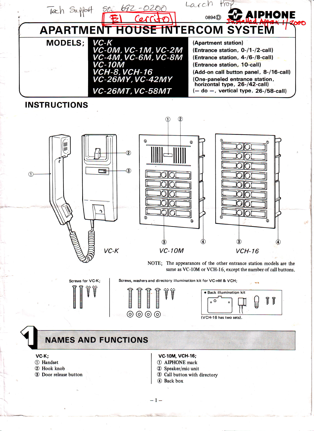
NOTE; The appearances
same as VC-lOM or
washers and directory
illumination
HHEH??
@@@@
of the other entrance
for
kit
o
(VCH-16
reffi
VCH-I6,
VC-nM &
illumination kit
Back
[]fl
has two sets).
VCH-
exceptthenumberof
VCH;
I 6
station models
gEF
are the
callbuttons.
VC-K;
Flandset
O
Hookknob
@
Door
@
release
button
VC.1OM,
AIPHONE mark
O
Speaker/mic unit
@
Catt button with
@
Back
@
-t-
VGH.16;
directorv
box
*
Loop-wiring system by 4 common plus
*
Maximum
*
Seven
*
Drectory
*
One-paneled
*
VC-BBX surface-mount back box for VC-nM & VCH
two VC-K stations
entrance station
illumination.
back
card
enlrance
per
models with 8- or l6-call add-on
stations
available, either vertical
I individual
apartment.
wires
panels
or
panels.
per
station
to meet
horizontal
(3
small
type.
+
l, if
door release is
to
larger
not required).
apartments.
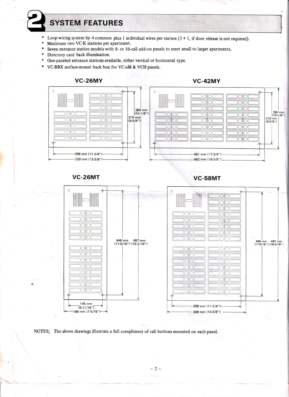
VC-26MY
/-tl
--|__l--:l
-
f
rT--
,v#
rlv!:J
v
r:
)L
I
r- r lt=-.
:l
r t
ji
/-l l/-l
rU
{ l
t t. lt r --j
(11-3/4")---J
298 mm
(13-3/8")
339 mm
VC-26MT
llilllil.-ilililililil
f-:!!]ur
-"lolto--l
!:]L-.
ir-- loltr-ril
l::::::::lr:] ZltlL-l
l-rol.r
--E---
.
I
tnolftrr
ti- rdhr,l
l rzrlZr--.:ll
L I
!_/
r'-r-r-thr-l
.--:1!L::1--i
:::-ta
i
(_lllr
lL
ll,t
__
l
-
--
r
tl
I
_:
)t
ll
_l
---l
vc-42MY
L:_]C
.
vtv
-^-:-
mm
260
t10-1
j
mml
,
rt"rl
I
.:::::
t8"l
:-T::^-f^-l
^ :i.-rr-rt
;
r-vtv_ _J.)z!:
Jvtv
_v
:;-h-
.jl[-r-] F
v
rl
rl
ll lr-------- rih--l
!
Lv
l
i: rl-r-
l
lr
tr--rnttr-..-- lt
l,
vr
vlvr
-----rl-^r__l
vlvr
rvllvr
ji
!l
:
I
26O
1
219 mm
(&5/8")
mm
0-1 /8" )
_l
(17-314"
1 mm
(19-3/8")
mm
492
vc-58MT
446
(17-9lr6") (19-3/16")
mm
487
mm
---ltr-',.
f,:
[L-]llLr
li.- r,lfn*,
jr-/
.
lL_
!)L
r-lo.j.ltor-ll
145 mm
l5-11 116"1
NOTES; The above drawings
-rl
]l
Jl
illustrate
a
fulI compliment
ri
+298mm
i
of call buttons mounted
-2-
mm
3tt9
on each
\U
(11-3/4")
(133/8")
panel.
BEFORE
-
Prohibitiors ard
YOU INSTALL AND
precautions
OPERATE
-
THE EOUIPMENT
"
.,i.
,
Operation;
DO NOT HOLD HOOK SWITCH
1.
HANDSET
2. Common
& communication
Calling
3.
RECEIVER
talk system.
ELEMENT AND
Your
are not
DOWN WHILE PICKING UP HANDSET, THE
conversation with entrance station can be
available between
Installation;
TERMINAL ON ANY
DO NOT CONNECT
1.
entrance
Only
one
2.
ANY
station
per
system.
Unit selection;
The VC-K/VC-M models are not compatibie with
*
Maintenance;
your
1. Clean
not
Do
2.
3. Call
button
SYSTEM
VC-K station with a soft cloth
on the entrance
water
splash
unit can be
replaced
individually.
COMPONENTS
station by
COULD CAUSE
room
two
TO AC
UNIT
the
existing
dampened with
hose,
etc.
HEARING DAMAGE.
stations,
POWER
models:
heard if
if installed, in the
VA-K/VAM-/VAM-A.
other apartment station
LINES.
neutrai household
TONE
CALL
same
cleanser. Never
Y
SOUNDS THRU
picks
apartment.
use thinner nor
THE
up handset.
benzine,
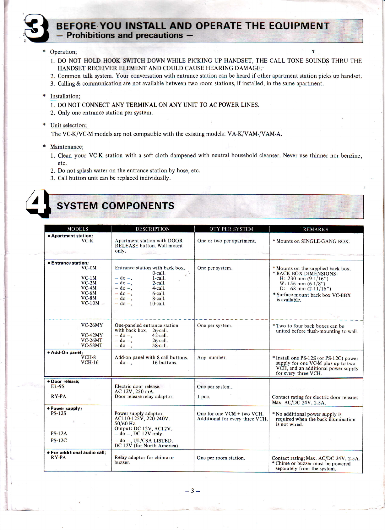
Apartment
RELEASE button. Wall-mount
only.
.
Entrance
.
Add-On
e
Door
EL.9S
RY-PA
.
Power
PS-l2S
PS-12A,
PS-l2C
.
For additional audio call;
RY-PA Relay adaptor for
station;
panel;
release;
supply;
VC-OM
VC.lM
VC.2M
VC-4M
VC-6M
VC-8M
vc-10Nt
VC.26MY
VC-42MY
VC.26MT
vc-s8MT
VCH.8
VCH.16
Entrance station with back box,
-
do
-
do
-
do
-
do
do
-
do
One-paneled entrance station
with back box,
-
do
-
do
-
do
Add-on
-
do
Electric door release.
AC l2V, 250 mA.
Door release relay
Power
AC1 10-125V,
50/60 Hz.
Output: DC 12V, ACl2V.
-
do
-
do
DC
btzzer.
station
-,
-,
-,
-,
-,
-,
-,
-,
-,
panel
-,
supply adaptor.
-,
DC l2V only.
-.
UL/CSA LISTED.
(for
12V
with
DOOR
0-call.
l-call.
2-call.
4-call.
6-call.
S-call.
l0-call.
26-call.
42-call.
26-caIl.
58-call.
with 8 call buttons,
buttons.
16
adaptor.
220-240Y.
North America).
chime or
One or two
per
One
per
One
number.
Any
per
One
pce.
I
for one VCM
One
Additional
per
One
system.
system.
system.
room station.
per
apartment.
+
for every three
two
VCH.
VCH
*
Mounts
on
SINCLE-GANG
*
Mounts
|
*
I
*
*
|
*
|
Contact rating
Max. AC/DC
*
Contact
*
on the
BACK BOX
H:
W:156
D:
Surface-mount
is available.
T*o
united before
Install
supply for
VCH, and an additional
for every three
No additional
required when
is not
Chime or buzzer
separately
DIMENSIONS:
230 mm
to four
(9-1116")
(6-ll8")
mm
(2-11l16")
68 mm
back boxes
tlush-mountine
one PS-12S
one VC-M
for electric
24V,2.5A.
power
wired.
the back
rating;
Max. ACIDC
from the system.
supplied back
back
box VC-BBX
can be
(or
PS-I2C) power
plus
up to two
supply is
must be
power
door release;
illumination
24V
Dowered
VCH.
BOX.
box
to wall
supply
,
2.5 A,.
-3-
+
oic\
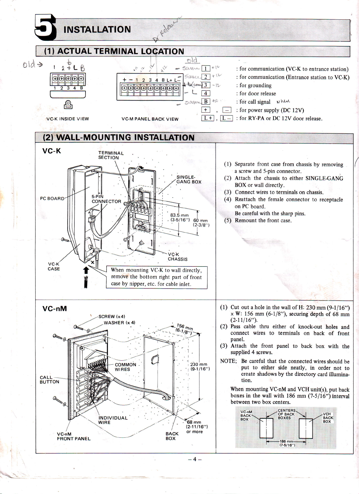
INSTALLATION
(1)
ACTUAL TERMINAL
-^
r
xitg
INSIDE VIEW VC-M PANEL
VC-K
LOCATION
--LE
BACK
VIEW
\..*[
'
r'
*
ffl
Dltt'
-ii
Et"
f;t
L-:--.1 r t- J
t-t-+l,
it:l
for
communication
for
communication (Entrance
for grounding
for
door release
for
call
signal
power
for
for
supply
RY-PA or DC
(VC-K
p
hl*
(DC
l2V door
to entrance
l2V)
release.
station to
station)
VC-K)
(2)
WALL-MOU
VC-K
PC BOARD
VC-nM
CALL
BUTTON
NTING I NSTALLATTOil
TERMINAL
SECTION
When
mounting
remove
case
by
COMMON
WIRES
the
nipper,
VC-K to
bottom
etc.
A
all
{.,,1
right
for
i
I
l
INDtvIDUAL
\{rRE
SINGLE-
GANG
VC.K
CHASSIS
wall
directly,
part
of front
cable
inlet.
BOX
230
(9-1l1
r
mm
6")
(1)
Separate
a screw and 5-pin
(2)
Attach the chassis
or wall
BOX
(3)
Connect
(4)
Reattach the female
PC
on
board.
Be
careful
(5)
Remount
(l)
(2)
(3)
NOTE;
out
Cut
x W:
(2-r1
Pass
connect wires
panel.
Attach the
supplied 4 screws.
When
boxes in the wall
between two box
a hole in the wall
156 mm
16").
l
cable
Be
careful that the
put
to
create shadows
tion.
mounting VC-nM
VC-nM
BACKI
.:
BOX
fiont
case
directly.
wires
to terminals on
with
the
the
front case.
(6-118"),
thru either
to terminals
front
either side
with
centers.
from
chassis
by removing
connector.
to either
connector to receptacle
sharp
panel
by the directory
186 mm
CENTERS
OF
BACK
BOXESi
SINGLE-GANG
chassis.
pins.
of H:
230
securing
of
connected
neatly, in
and VCH
knock-out
on
to
back box
(7-5116")
i:
depth
unit(s), put
mm
back of front
wires
order
card illumina-
VCH
BACK
BOX
(9-l/16")
of 68
mm
holes
and
with
the
should be
nor to
back
interval
(
BACK
BOX
-4-
186
mm+
t7-5t16"1
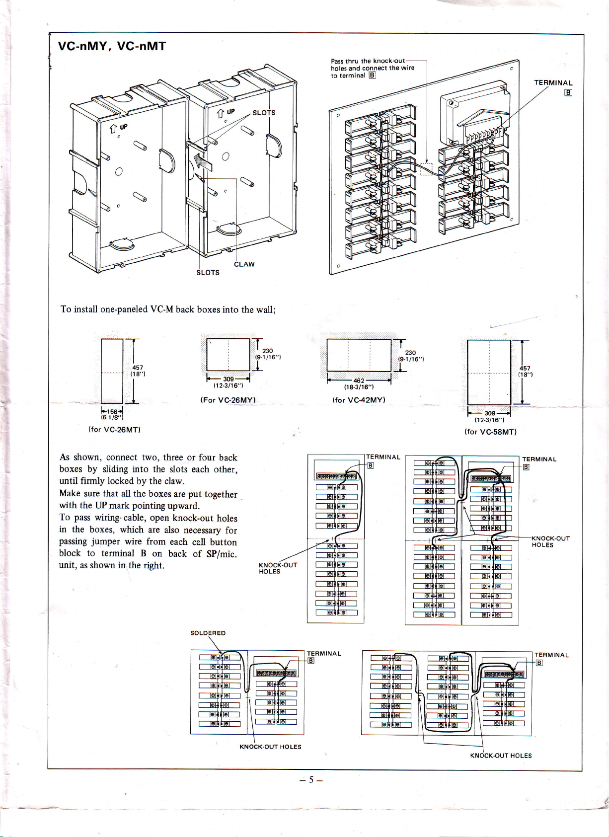
VC-nMY,
t:
o
VC-nMT
t
uP
,r',sLors
thru
Pass
holes and
terminal
to
the knockoul
the
colllect
[El
wire
TERMINAL
E
To install one,paneled VC-M
l*rse.l
(6-1
/8")
(for
VC-26MT)
As
shown, connect two, three or
boxes by
until firmly locked
Make
with
To
in
the boxes,
passing
block to terminal
unit,
sliding into the slots
by the
that
sure
the
pass
all the boxes
UP mark
pointing
wiring-cable,
which are
jumper
wire
B
as shown inrthe right.
claw.
upward.
open
also
from
on
back boxes into
ri----i-]-I| , llr.o
|
titI
F.;;+
(12-3116"1
(For
VC-26MYl
four
back
each other,
put
are
knock-out
each
back
together
holes
necessary
call
button
of
SP/mic.
:
for
the wall;
(s-tlro"l
|
KNOCK-OUT
HOLES
-*,
{18-3/1
(for
VC42MYl
6")
:,
:191/16")
',1
"
80
KNOCK.OUT
HOLES
TERMINAL
5-
KNOCK.OUT
HOLES
' - ---*''e:
I

(1)
WHEN
USrNG
AC-OPERATED
DOOR
RELEASE;
F\
U
irudl
ENTRANCE
VC-lM
l,Jl
I tfrt-lflt I
t-=-i
l..l
STATION
APAR
VC-K
m
li
lrl
TMENT
STATION
For North America only;
M
(21
BASIC SYSTEM
M
wlTH
T-----l
i
l-
rll
itt-llV,ll
iu"
L-----.J
DG-OPERATED
No.
1
i
T----t
I
OOOR
No.2
| |
rrr u i I--l
u"i
i
L---J
u;
1
i
i
R:
I
L
AC
---l
I
I
-.-.-
DI RECTORY
@H
POWER
PS-1
(or
TERMTNAL
ON
DOOR RELEASE
Rating;
DC 12V
ro;EEJ
SUPPLY
2SlPS-1
PS-1
2C)
EACH
CARD BACK I
(on
VC-nM)
2A
I
I
{
L
LLUMINATOR
ENTRANCE
VC.4M
In
aPIRTMENT
@
called
Dc-operated
@
For
call extension,
@
STATION
#
by entt4nce
station.
d<iblnrplease
use either
INSTALLATION
#@
t-t
ll
r
two room
,
e
Calling is not
can
be
connected
chime or
*(t\
r \:9/
il
U
stations
can be
available
to
ILTI
between room
bvuzzer locally
signalled
, El
terminals
available,
by tone
stations
simultaneously,
A
and B.
directly.
rated less than
DC
24V
|
|
when
,2.5A.
ATTACH
2 SCREWS SUPPLIED,
NOTE; VC-1 M-VC-10M
THE PLATE
VCH-16; Use
TO
WITH LAMP
positions
"A"
OB
& VCH-8;
A
and
"8"
POSITION
DOWNWARD.
position
Use
B.
B.
WITH
-7 -
lL-
To
'.4
remove;
Desolder the bus
O
Unscrew the teiminal.
@
Detach
@
Push
the claw.
O
Be careful
oerncn
6
t
wire.
the switch unit.
lose
not to
f
the spring
and button.

,l
I
ENTRANCE STATION
o=-J
-ffi|il
flilil
CALL
ol
button of
apartment.
o lafl
-R
Depress
corresponding
After apartment station
replies, talk handsfree.
SPECIFICATIONS
{.
Power
*
*
x
x
*
source:
Current consumption:
Calling:
Talk
channel;
Wiring:
Wiring
distance:
o
Between
Diameter 0.6
Distance
AWG r
Distance
o
Between
Diameter
Distance
AWG
Distance
Dimensions;
DC 12V. Use PS-l23 or PS-l24
80 mA
100 mA
Electronic buzzer tone
Single channel, common
4 wires in common + 1 individual
(Line
resistancei
VC-M & VC-K:
power
supply
and door
Electronic
at (two)
(and
brzzer sounds
room station(s).
at
extension. if
call
installed.)
(or
PS-l2C in North America)
(at
intercom)
(at
lamp).
(Frequency;Approx.
talk
system.
per
apartment
Max.
35 ohm
looped).
mm 0.65 mm
m 330 m 500 m
280
(Line
station;
0.6
resistance:
mm
30m
600 Hz.)
(3
wires
APARTMENT STATION
Pick
up handset
to reply.
Depress
RELEASE
tivate
door release.
power
supply.
plus
f . if door release
22 AWG
1
00'
,1
Max. 4 ohm
looped)
is not included).
mm
0.8
20 -A.\YG 18 AWG
1,650'
0.65 mm 0.8 mm
40m 60m 90m
AWG 20 AWG 18 AWG
22
t25',
a
190' 28O',
and hold Door
button
to ac-
1.0 mm
800 m
2,s 00'
1.0
mm
panel
VC-M
VC-M back box 230 mm
VC.K 210 mm
VC-BBX 264mm
Aiphon€
year
examination
whether
This
instructions
This
This
will not
Aiphone Co.,
Aiphone Corporation, Bellevue,
warrants its
delivery
after
there
warrantv
furnished, nor extended
warranty does
warranty covers bench
responsible
be
Ltd.,
vc.M-r(E,0894D
products
to the ultimate
disclose
shall
is a defect
not apply
shall
not
Nagoya, Japan
to be defective
materials and/or
in
cover
for
any
free
to be
user and
to any Aiphone
to units
batteries
repairs
Wash ington
or damage
only, and any
costs incurred
Height
260 mm
(lO-114")
(9-Il16")
(8-114"\
(10-3/8")
WARRANTY
from
defects
will repair
and under
workmanship;and
product
which
caused by
involving on site service calls.
material
of
free
of charge
warranty.
which |fas
have
been
repiirs must
batteries
Aiphone
whether
repaired
be
-8-
width
186 mm
156 mm
190 mm
workmanship
and
or replace at ho charge, should
reserves unto
product
not
or
the
subiect
been
or altered outside
used in connection
made
at
to
the shop or
(7-sl16")
(6-118")
(3-1l8')
80 mm
(7-r12")
under
itself
is
misuse, neglect, accident, or to use
of
the
with
place
designated
Depth
2mm(s164")
normal
the sole
within
factory.
product.
the
68 mm
6l mm
52
and service
use
it
become defective upon
nght to make
warranty.
the
in writing
by Aiphone. Aiphone
for
the
mm
period
a
final
in
(2-11116")
(2-318")
(2-ll16"\
of one
which
decision
violation
of
@#nflijffii-t
Printed in Hong Kong
(E)
 Loading...