

Page 1
83640300 0795©
® AlPHONE
TB-M Series
10-call PanTilt Door Adaptor
Model: TB-ADM10
INSTALLATION & OPERATION MANUAL
CONTENTS
1 SYSTEM OUTLINES COMPONENTS................................................................................................................... 1
2 NAMES & FEATURES.............................................................................................................................................2
3 PRECAUTIONS ON INSTALLATION & WIRING.....................................................................................................2
4 WIRING....................................................................................................................................................................3
5 MOUNTING..............................................................................................................................................................5
6 OPERATIONS .........................................................................................................................................................6
7 TECHNICAL PRECAUTIONS..................................................................................................................................8
8 SPECIFICATIONS...................................................................................................................................................8
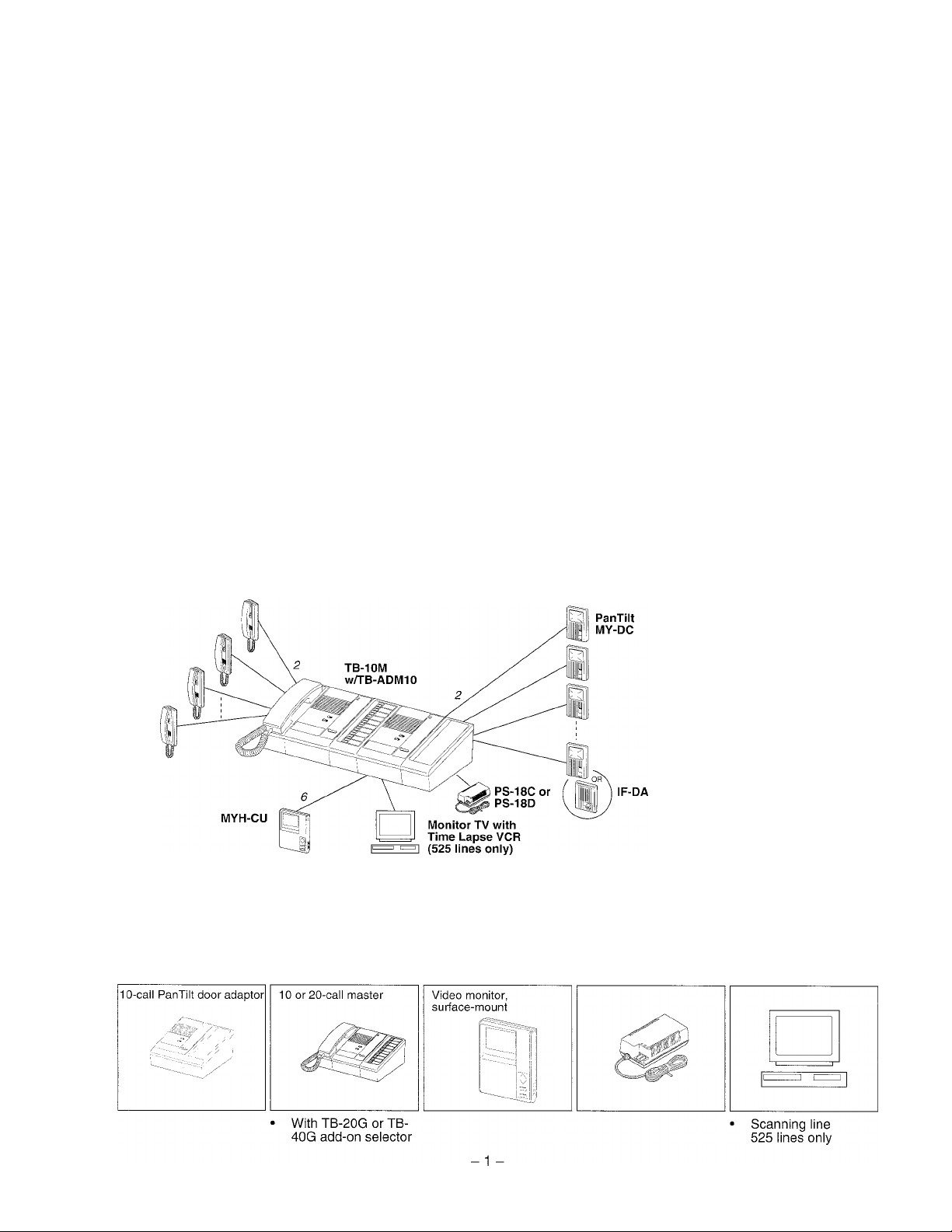
SYSTEM OUTLINE & COMPONENTS ----------------------------------------------------------
TB-ADM10 Is a 10-call PanTilt door adaptor for use with TB-M Internal Telephone System. Using TB-SE
sub handset capacity, TB-M may incorporate up to 10 MY PanTilt or lE/IF audio door stations.
TB-SE
★ A monitor TV must be used for Auto-Scanning, which exceeds usual
2.5 minutes on MYH-CU (together with Time-Lapse VCR).
■ Components available
TB-ADM10 TB-10M, TB-20M
MYH-CU
PS-18C, PS-18D
Package contents
TB-M 10-call PanTilt door
adaptor (TB-ADM10)
Junction cable (2)
Packet of screws
Installation & Operation Manual
Monitor TV,
Time Lapse VCR
Page 2
■ Components available ' Video door stations, PanTilt or Wide-angle
MY-DC
Others: MY-DG, metal panel,
MY-EA
MY-FA
MY-CA
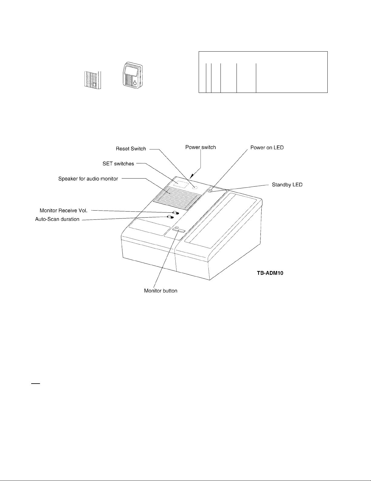
NAMES AND FEATURES
MY-DS
Wide-angle
Audio door stations
IF-DA lE-JA
IliV
1
Others: lE-FY, aluminum panel
lE-DC lE-NC
..
.........
1
for visual monitoring selectively
or auto-scanning
FEATURES
Max. 10 PanTilt video control and communication
Outdoor remote can be either PanTilt MY Series, audio lE/IF Series, or
overhead camera
Auto-scanning with 10 to 30 second duration
Video output to monitor TV and/or time-lapse VCR (525 lines only)
> PRECAUTIONS ON INSTALLATION & WIRING ---------------------------------------------
A
CAUTION
if TB-ADM10 is an electrical device operating on low DC voltage. Do not connect any terminal
on any unit to AC power lines to prevent fire or unit damage.
★ Do not attempt to install or connect wires on TB-ADM10 while system's power supply is
plugged in.
if TB-ADM10 is for indoor installation only. Do not install outdoors.
■ Before installing TB-ADM10, refer to Precautions stated in TB-M Series Manual.
-2-
Page 3
WIRING
Terminals block layout
Terminal symbols
1. Door station audio, video & PanTilt signals
1A1, 1A2 (door 1) ~ 10A1, 10A2 (door 10)
IA22A23A24A25A26A27A28A29A2IOA2UI U2 B1 B2
@©©©©©©©©0®©©©
1Ai2Ai3Ai4Ai5Ai6Ai7Ai8Ai9Ai10Ai b b N1 N2 H-------------------------
©©©©©©©©©©©©©©©©
10 pairs of A1, A2
terminals for PanTilt
door stations
★ Do not cross wires with
other door stations'.
DCI8V
TB-M entry call system
TB-M is capable of connecting only one entry call adaptor, audio or video. So, it is not possible to use
TB-AD1 or TB-AD10 adaptors together with TB-ADM10 within a system.
Video monitor capacity
Only one MYH-CU video monitor can be mounted along with TB-M console.
Cable
Using cable must be a parallel cable for each door station. Do not use multi-pair cable.
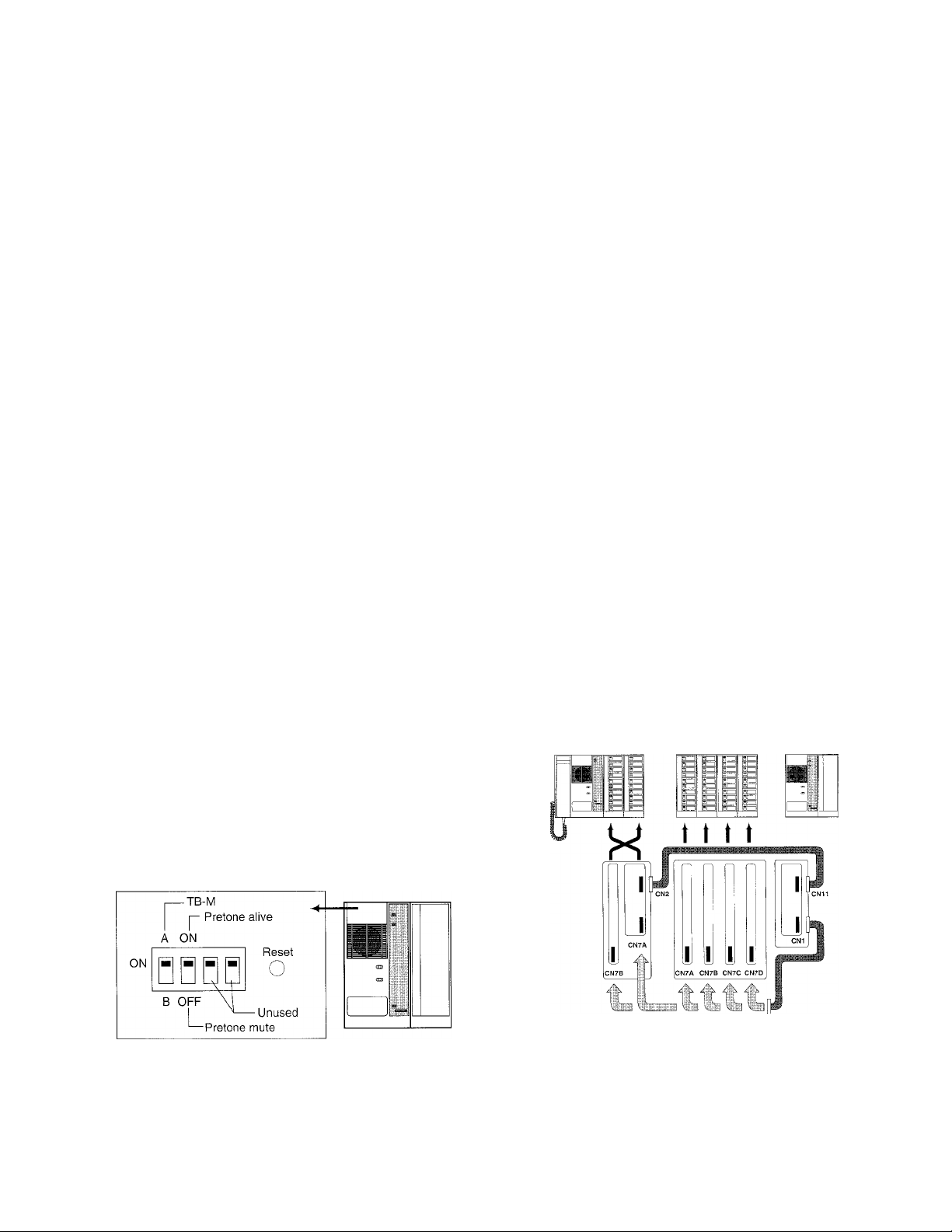
Connecting TB-ADM10 to TB-M or TB-G add-on selector
TB-ADM 10 is equipped with two junction cables of 100cm long. Plug in connectors to inside sockets,
which are located on PC board of TB-M & TB-G. It decides automatically a select switch bank for door
stations.
★ When TB-ADM10 is plugged to TB-M or TB-G, the terminals of corresponding switch banks can
not be used for TB-SE subs.
Pre-tone on/off setting
Remove a cover on top left of TB-ADM 10. Do
not change A setting, which is preset for TB-M.
The second switch when put to above ON
position, validates pre-tone, which sounds at
door station (any), upon selected by TB-M.
2. For MYH-CU monitor
+, - : 18V DC power supply
U1,U2 ; control
B1,B2 : Video output
3. For external device
b, b : Control of Time-Lapse VCR
(to its control terminal)
Coaxial cable connector to video input on
Monitor TV
N1,N2 : unused
Junction cable alignment
TB-20M (TB-10M) TB-40G (TB-20G) TB-ADM10
Reset switch
When TB-ADM10 malfunctions, press Reset
switch.
TB-ADM10
-3-
Page 4

WIRING DIAGRAM
• TB-10M with five MY video entries
Five PanTilt
door stations
MY-DC
Non-Polarized
10-call PanTllt
adaptor
TB-ADM10
Pre-tone
1A1
1A2
2A1
2A2
-3A1
-3A2
4A1
4A2
ON or OFF
B1
B2
U1
U2
Video-monitor
MYH-CU
Impedance Matching
Remains
1A1
1A2
U1
U2
Non-Polarized
In place of MY-DC,
audio lE/IF Series
may be connected
★ In this example, 6-10
A1, A2 terminals must
be vacant.
• One TB-ADM10 per single or dual TB-M system
• Max.10 PanTilt door stations, or MY-CA in
MYW-CA or lE/IF Series audio.
• Reduces TB-SE subs capacity.
★ When 1A1, 1A2 - 5A1, 5A2 terminals are
used on TB-ADM10, # terminals 1 - 5 must
be vacant on TB-M.
• TB-AD1 or TB-AD10 audio door adaptors
can not be connected.
5A1
5A2
6A1
6A2
7A1
7A2
8A1
8A2
9A1
9A2
10A1
10A2
CN9
N1
N2
CN1
CN11
Use junction cable
supplied.
I
I
CN7A
CN2
©
©
lU-
To: control terminal
of Time-Lapse VCR
10-call master
TB-10M
To: Monitor TV
and/or Time-Lapse
VCR, etc.
P
(525 line only)
★ In this example,
1-5 terminals
must be vacant.
Handset sub j
TB-SE
: PS-18C or PS-18D
• Do not use any other power supply.
• Plug in TB-ADM10 to a designated socket
as per table below;
TB-ADM10
CN1
connects to:
CN11
connects to :
TB-10M TB-20M
CN7A CN7A or
CN7B
CN2 CN2
TB-20G TB-40G
CN7A or
CN7B
CN7A.7B,
7C or7D
— —
★ Remain
unused
-4-
12V
T
R
AC15-16V
or DC18V
IN
10-
Non-Polarized
D
D
To PS-18C or
PS-18D Of
TB-ADM10
Page 5

MOUNTING
• Desk-top mounting
Wall-mounting
TB-ADM10
1. Remove 2 screws on front panel, removing 2 covers.
2. Lift off front case holding sides at top.
3. Disconnect TB-ADM10, plugging off connector.
4. Open a cable inlet hole (rubber part) on rear or bottom of chassis.
5. Pull in cable(s), and make wire terminations.
6. Use attached cable clamp(s) for neat and secured connection.
7. Reconnect and mount front case to chassis, attaching the covers to place.
★ For wall-mounting, the chassis must be mounted upside down.
When wall-mounted with TB-M (and TB-G)
Decide an exact location of TB-M master, and the next unit(s) atachedly mounts with the guides below;
TB-M master TB-G add-on TB-ADM10
selector
Wall-mounting guide
Master
TB-10M
TB-20M
★ Processing conductor end
Attached
TB-20G 202.5
TB-40G 277.5
TB-ADM10
TB-20G 240.0
TB-40G 315.0
TB-ADM10
5C-2V or
RG-59/U (20GA)
li'v
Guide A
225.0 — —
262.5
11mm (7/16”)
3mm (1/8”)
8.5mm (3/8”)
Attached Guide B
TB-ADM10 172.5
TB-ADM10 247.5
TB-ADM10
TB-ADM10 247.5
— —
3C-2V or
RG-59/U (22GA)
Fold back
Unit: mm
172.5
Page 6

OPERATIONS
Pan and tilting MY camera
While MYH-CU monitor is on, pan and tilt the MY door camera.
Receiving a call from MY door station
1. Press CALL button on MY door station.
2. Intermittent tremolo rings on TB-M. The LED is lit to indicate.
MYH-CU turns on. It times out in 40 seconds.
3. Pick up TB-M handset, and press a designated button.
4. Communicate. Image is alive for 2-1/2 minutes.
5. When MYH-CU turns off, press MONITOR button on
TB-ADM10 to resume.
6. At conclusion, hang up TB-M handset. MYH-CU turns off.
Camera
tilts down.
Camera pans to right.
Calling an MY door station
1. Pick up TB-M handset, and press a designated button.
2. MYH-CU turns on. Pre-tone is heard at MY door station.
The channel is established. Call by voice.
3. Communicate.
When called by MY door station, while communicating
1. A call-in LED is only lit. Image on MYH-CU remains unchanged.
2. To reply, press an LED-lit button, and the image is switched.
Selective & handsfree audio/visual monitoring
1. On TB-ADM10, press MONITOR button.
The LED above is lit.
2. Within 5 seconds, press a designated
button of MY door station you wish to
monitor. The LED is lit.
3. MYH-CU turns on. Hear audio from
TB-ADM10 speaker.
4. To call, pick up TB-M handset.
When called by MY door station during visual
monitoring
1. Call-in LED is only lit, with audio call tone muted. The image is kept on,
2. Pick up TB-M handset. The channel to an MY door station being monitored is established.
3. Press a desinated button of calling MY door station.
4. Image of calling MY comes on. Communicate.
-6-
Page 7

Auto-scanning - 60-minute handsfree audio-visual monitoring of MY door stations, skipping TB-SE
and lE/IF audio door stations.
★ With a duration of 10, 20 or 30 seconds, view image of MY door station in succession from top to
bottom of TB-M switch bank, guided by a flashing of cail-in LED.
1. Press MONITOR button on TB-ADM10 for 2 seo. or more.
2. The attached LED turns on flashing. Image of MY door 1 comes on on Monitor TV (and MYH-CU).
Audio is available from TB-ADM10.
3. After preset seconds, image of next door comes on, which will be stabilized In 2 seconds.
4. MYH-CU video monitor auto-turns off in 2-1/2 minutes.
5. To continue, view only on Monitor TV. Do not press any Monitor button. TB-ADM10 makes next
rounds of scanning.
6. To conclude, press MONITOR button on TB-ADM10.
OR Auto-cancels after 60 minutes. Restart from 1.
Receiving an MY door caii during auto
scanning
1. Intermittent tremolo sounds from
TB-M speaker.
2. Pick up TB-M handset, and press an
LED-lit button.
3. Image of a calling MY comes on.
Communicate.
4. Hang up handset to conclude.
5. Press MONITOR button on TB-ADM10
for 2 sec. or more to restart from MY1.
Auto skips lE/IF
Series and TB-SE
★ Auto-scannning is terminated by lifting handset on TB-M.
It instantly establishes talk channel to an LED-lit MY door station.
Calling is void from the MY just being scanned.
Presetting MY door camera angie
Any PanTilt MY door stations, except MY-DC, MY-DG, can change its initial center position to a
desired camera angle, so that it turns back at each start/end of operation.
To preset: - ★ Do not pick up TB-M handset.
1. Press a desginated button of MY door on TB-M. See the call-in LED is lit.
2. Hold down BACKLIGHT button and press MONITOR once on MYH-CU.
Keep holding down BACKLIGHT. In about 5 seconds,
3. See MYH-CU screen bottom (1/4) starts flashing. Release from BACKLIGHT.
It's ready to preset (or BACKLIGHT to cancel).
4. Pan/tilt the camera to direct its angle to a standing point.
5. Lastly, press MONITOR button.
★ When an entire system is powered off, the preset memory can be
erased. Reprogram.
Adjustments
• Audio monitor voiume from TB-ADM10 speaker, adjustable or muted, while visual monitoring or
auto-scanning.
• Auto-scanning duration: Set to either 10, 20 or 30 second from left.
-7-
Page 8

TECHNICAL PRECAUTIONS
Video recording
• TB-ADM10 has CN9 video output connectable to a local Monitor TV or VCR (525 line only) with
coaxial cable. Record video on VCR,(no audio) It is not an automatic recording.
• When a Time-Lapse VCR is connected with additional non-polar b, b wires to VCR’s control
terminals, all images on MYH-CU can be recorded automatically, (no audio)
Transfer of MY door call
It is not possible to transfer a call of MY or lE/IF door station. If TRANSFER switch is
wrongly pressed, hang up TB-M handset, and press TRANSFER switch to clear.
Monitoring
For visual monitoring (any MY), always use MONITOR button on TB-ADM10.
To monitor lE/IF, press a designated button, lifting TB-M handest. TB-SE sub can never be monitored.
SPECIFICATIONS
Power source:
Current consumption:
No. of door stations.
Call-in timer:
Video timer:
Auto-scanning timer:
Wiring:
18V DC. Use a PS-18C or PS-18D power supply.
700mA max. (TB-ADM10 only)
10 (max.) either PanTilt MY or lE/IF Series door stations.
40 seconds
2-1/2 minutes
60 minutes
2 conductors, non-polarized per door station
6 conductors, TB-ADM10 to MYFI-CU
Wiring distance:
From TB-ADM10 to PS-18C or PS-18D
———___ Gauge
Distance —~
From TB-ADM10 to PanTilt MY
to MY-DS 330' 650'
to lE/IF audio
Distance ———
Gauge
22AWG 18AWG
165'
450' 1,180'
18AWG 16AWG
16'
330'
33'
O.65mm0 1 .Ommo
50m 100m
100m 200m
150m 360m
1 .Ommo 1.2mm0
5m 10m
Dimensions (H x W x D): 92 x 195 x 230 (mm). 3-5/8" x 7-5/8" x 9"
Weight: 1.5kgs. (3.31 lbs.) approx.
This equipment has been tested and found to comply with the limits for a Class B digitai'device, pursuant to Part 15 of the FCC Rules. These limits are designed
to provide reasonable protection against harmful interference in a residential installation. This equiprnent generates, uses, and can radiate radio frequency
energy and, if not installed and used in accordance with the instructions, may causé harmful interference to radio communications. However, there Is no
guarantee that interference will not occur in a particular installation. If this equipmeht does cause harrhful inteference to radio or television reception, which can
be determined by turning the equipment off and on, the user is encouraged to try to correct the interference by one or rnore of the following measures:
• Reorient or relocate the receiving antenna. • Connect the equipment; into an outlet on a circuit different from that to which the receiver is connected.
• Increase the separation between the equipment and receiver. • Consult the dealer or an experienced radio/TV technician for help.
'•i*
Aiphone warrants its products to be free from defects of material and workmanship under normal use and service for a period of two
years after delivery to the ultimate user and will repair free of charge or replace at no charge, should it become defective upon which
examination shall disclose to be defective and under warranty. Aiphone reserves unto itself the sole right to make the final decision
whether there is a defect in materials and/or workmanship; and whether or not the product is within the warranty.
This warranty shall not apply to any Aiphone product which has been subject to misuse, neglect, accident, or to use in violation of
instructions furnished, nor extended to units which have been repaired or altered outside of the factory. This warranty does not cover
batteries or damage caused by batteries used in connection with the product.
This warranty covers bench repairs only, and any repairs must be made at the shop or place designated in writing by Aiphone.
•Î-
Aiphone will not be responsible for any costs incurred involving on site service calls.
«I»
WARRANTY
♦ ‘*‘1* »1* ♦I*. ♦
Aiphone Co., Ltd., Nagoya, Japan
Aiphone Corporation, Bellevue, WA, USA
TB-ADMIO-I(E) 0795F
-8-
COMMUNICATION SYSTEMS
©
AIPHONE
HOME, BUSINESS, INDUSTRY.
Printed in Japan (E)
 Loading...