

Page 1
O AIPHONE
TELEPHONE TYPE INTERCOM TB-F series
832841 TB-F-l-0986 ®
MODELS TB-1F (single-way) TB-3F (three-way)
TB"6F (six-way) TB“12F (twelve-way)
COMMON TALK SELECTIVE RING
- INSTRUCTIONS
COMMUNICA
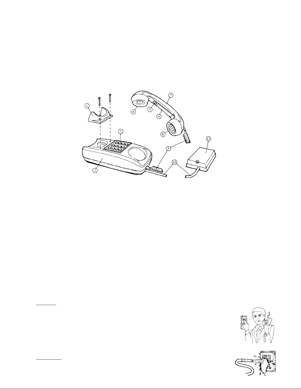
NAMES AND FUNCTIONS
Receiver cradle for wall mounting, included
Station selector buttons
Case
(7) Receiver
(2) Paging button
Directory card
(7) Handset
Microphone
Coil cord
Terminal cord
Terminal box
SPECIFICATIONS
* Power source:
Current consumption:
Calling:
Paging:
Wiring:
BEFORE YOU INSTALL AND OPERATE THE EOUIPMENT
* Operation;
1. DO NOT HOLD HOOK SWITCH DOWN WHILE PICKING UP HANDSET. THE CALL
TONE SOUNDS THRU THE HANDSET RECEIVER ELEMENT AND COULD CAUSE
HEARING DAMAGE.
* Installation;
1. DO NOT CONNECT ANY TERMINAL ON ANY UNIT TO AC POWER LINES.
2. Be sure to remove plug of power supply from AC outlet before you open the unit or make
wiring connections.
3. Avoid running the connecting wires thru doors, windows or between furniture, which may
pinch and disconnectect the wires.
4. The intercom equipment must be installed in as dry and dust-free environment as possible.
* Maintenance;
1. Clean your intercom equipment with a soft cloth dampened with neutral household cleanser.
Never use thinner nor benzine, etc.
2. Do not splash water on the door station by hose, etc.
DC 12 volt. Use PS-12A (PS-12C in North America) AC adaptor. If your system does not in
clude door station or paging system, you may use PS-12S AC adaptor.
70 mA maximum per station.
Push-button station selection. An electronic tone sounds when the selected station button is
depressed.
Use PB-1 paging adaptor in conjunction with standard paging amplifier and speakers.
Up to 17 conductors may be required. Please refer to wiring diagram showing system that
meets your requirements.
Prohibitions and precautions -
NEVER
NEVER
- 1 -
Page 2

FEATURES
* Up to 13 stations can be connected in a system.
* Common talk system for phone communication. (Conference calls can selectively include up to 6 stations)
* Separate paging channel. Paging announcement may be done separately and independently from phone communication.
* ECM (Electret condenser mic) provides excellent voice fidelity.
* Phone designed for either desk use or wall mounting. Terminal cord may be pulled out from either the top or the bottom
of the phone.
OPTIONS
* Door station IC-DC can be installed with adaptor DB-U. Up to two door stations may be connected to a maximum
of 12 phones.
* One call sub station TB-A is available where paging or door station communication is not required (TB-A is designed for
wall mounting only).
* Phone system may be connected to existing paging and background music system using adaptor PB-1.
* Talkback paging available through existing paging system using adaptor PB-2 in conjunction with PB-1.
* A call in a noisy area may be annunciated by a separate buzzer or bell using the RY-AC relay.
EQUIPMENT AVAILABLE FOR USE WITH YOUR TB-F PHONE SYSTEM
■V
I
TB-IF: 1 call master station with paging
button (will not work with door station).
TB-3F: 3 call master station with paging
button and door station capability.
TB-6F; 6 call master station with paging
button and door station capability.
TB-12F; 12 call master station with paging
button and door station capability,
TB-A: 1 call sub station without paging or
door station capability. Wall mounting only
(not avaialble in U.S.A.).
IC-DC: Surface mount standard door sation.
DB-U: Adaptor for door station. Requires
between one door station and TB-F phones.
PB-1: Paging adaptor. Connects all TB-F
phones to a paging system and background
music source.
PB-2: Paging adaptor with talkback. Must
be used in conjunction with PB-1.
PG-lOA, PG-30A, PG-60A: UL & CSA
approved paging amplifier. lOW, 30W, 60W
(available only in North America).
B
:===
^ ,1111
lllli
SP-3: Paging speaker. Complete and ready
to install including round flush mounting
frame.
NCH-2: Noise-resistant handset.
For field installation only.
RY-SP: Local speaker cutout relay.
RY-AC: Relay for operating external device
such as additional caUing buzzer or bell,
door release, etc.
EL-9S: Electric door release. Requires sepa
rate transformer and RY-AC.
PS-12C; CSA & UL Listed power supply
(available only in North America).
PS-12A: Power supply. Standard
where except North Arnerica.
PS-12S; Power supply. May be used in a
TB-F system which does not include door
station or paging system (not available in
North America).
PG-3: 3-watt paging amplifier.
every-
PG-lOB, PG-30B, PG-60B: Standard paging
amplifier. lOW, 30W, 60W.
INSTALLATION
Do not attempt to install you intercom system until you have read and thoroughly understood the installation procedure.
Aiphone’s warranty is void if system is installed in a manner other than described in this manual.
Lay out your system in advance. Determine the exact location of each station. We recommend a full complement of wire
be installed, even though you may not initially be installing the maximum number of stations available to your system. This
way, should you decide to add a station later, you can avoid running additional cables to existing stations.
Page 3
WIRING REQUIRED
TB-l F: 5 Conductors maximum
TB-3F: 8 Conductors maximum
TB-6F: 11 Conductors maximum
TB-12F; 17 Conductors maximum
Refer to the chart below and select the proper wire gauge to meet your requirements.
AWG WIRE SIZE
MAXIMUM COMMUNICATION DISTANCE
BETWEEN MOST DISTANT PHONES
MAXIMUM COMMUNICATION DISTANCE
FROM PHONE TO DOORS STATION
DIAMETER OF WIRE 0.5 mm
MAXIMUM COMMUNICATION DISTANCE
BETWEEN MOST DISTANT PHONES
MAXIMUM COMMUNICATION DISTANCE
FROM PHONE TO DOOR STATION
24 AWG 22 AWG 20 AWG
1200' 2000' 3000'
300' 500'
0.65 mm 0.8 mm
400 m
90 m 150 m 230 m
650 m 1000 m
700'
Begin your installation with station #1. A space is provided at the left of the diagram to write in your color code. Note
the position of the C terminal at each station. Be sure you wire each station correctly.
After installing your second station we recommend that the power supply be connected to the ©and ©terminal lines at a
convenient location and that a test be made for calling and talking between each station. As each additional station is install
ed re-test between each station. Unplug power supply while making wiring connections.
ACTUAL TB-F TERMINAL LOCATIONS
TB-1F
TB-3F
TB-6F
for receiving call and talking
©
for connecting door station
for both door station and paging
©
for power supply
o
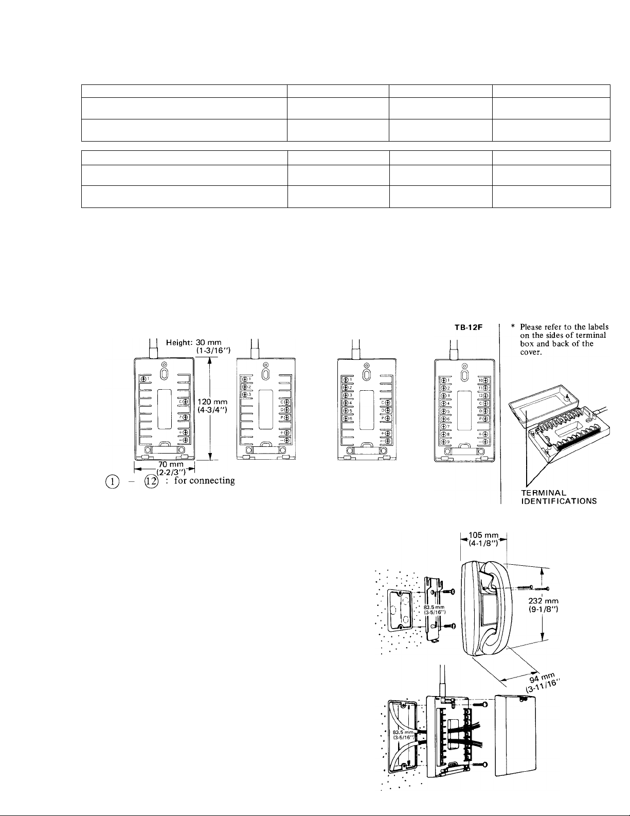
INSTALLATION FOR WALL MOUNTING
1) Attach the mounting bracket to wall or
single gang plaster ring.
2) Attach handset cradle included, as shown
in illustration.
NOTE: Terminal cord may be pulled out
from either the top or the bottom
of the body, or straight back to
plaster ring.
INSTALLATION OF TERMINAL BOX
(Can be mounted easily to wall or single gang
box.)
1) Remove screws and cover as shown.
2) Attach bottom case to wall or 1-gang box.
3) Replace cover after wiring.
- 3
Page 4

TB-12F ALL MASTE
TB-12F PHONE SYSTEM with PAGING
-4-
Page 5

R PHONE SYSTEM
I STATION
1
2 ^
3<^
4^
5^
61^
7^
c#
9^
lOli^
11^
12^ 12^
D(^
P@
+ 1^ + ©
dA
i<!^
2<<^
3^
4^
5^
6^
7^ 7^
c#
1l(^^
P@
-1^
I * Place PS-12A (or PS-12C)
I power supply near the
ter of the system.
9
STATION
10
/
1^
2^
3^
4^
6^
8(J^
C®
1l(^)
10^
D0
1
2<^
■2,^
4^
5<!^ 7^
7(1^
8^
10<!^
c«
1^
D@
P©
STATION
12
'—^
7©"
7©'
3©
7©"
6©
7©'
8©
9©
10©
11©
c#
12©
D©
P©
.-A
I STATION
13
/— ^ ■>
T©
7©
7©
7©
7©
7©
7©
8©
9©
n©
12©
C#
D©
P©
+ ©
-©)
and BACKGROUND MUSIC SYSTEM
STATION
8
T©
7©
3©
4©
5©
6^
7©
c#
w>
io©
11© 11© 11©
12©
8©
D0
70
+ ©
I STATION
9
>
1©
70
3©
4© 40
50
I STATION
10
—s —s
1 ©
70
30
50
60 60 60
70
80
c#
Id©
70
80
90
C#
120
90
D©
rio©
D©
P0
■+0
r©
¡STATION
11
1©
70
3©
4©
50
70
80
90 90 90
10©
C#
12©
11©
D©
P0
70
-5-
STATION
12
T0
70
30
70
2©
3©
40 4©
50
5©
60
70 70
80
1C© 1C©
11©
11©
C#
C#
D©
P0
70
m
D©
P0 P©
+ ©
-M
STATION
13
PB-1
•
PAGING SPEAKER
1
_____ 1
-------------------------1
NO-POLARIZED
-------
1
PG-AorPG-B
/T
---
A©
©
GND
M©
0
GND
7^
L >
■
() ()
r—1
ACKGROUND
11 <501 IROF
OUTPUT
PS-12A or
PS-12C
Power Supply fiisTT^
c~ L- " * 1
AC Ck I
+ ©
-©
PB-1 paging adaptor must be connected directly
to PS-12A (or PS-12C) power supply.
Page 6

VARIATIONS TO STANDARD INSTALLATIONS
Any combination of TB-F series phones and accessories shown on page 2 of this manual can be intermixed to develop a
communication system to meet your requirements. Installation examples below show TB-6F as master station which may be
replaced by either TB-3F or TB-12F.
EXAMPLE NO. 1: TB-F SYSTEM WITH ONE MASTER AND SEVERAL SUBS
1) This example shows six TB-IF phones connected to one TB-6F.
2) Paging system may be added using PB-1 adaptor.
PS-12C
Power Supply
EXAMPLE NO. 2: TB-F SYSTEM WITH TALKBACK PAGING EQUIPMENT REQUIREMENTS
1) TB-F system shall consist of TB-IF, TB-3F, TB-6F or TB-12F phones.
2) One PS-12A (or PS-12C), one PB-1, one PB-2, one paging amplifier with 70 or 100 volt line and output of less than 50
watt RMS, and appropriate paging speakers as required must be used.
3) Door station may be included in system with paging or talkback paging.
NOTE: * PB-1 and PB-2 paging adaptors must be connected directly to PS-12A (or PS-12C) power supply.
-6-
PB-2
PB-1
Page 7

EXAMPLE NO. 3: TB-F SYSTEM WITH 2 DOOR STATIONS AND ELECTRIC DOOR RELEASE
• Maximum of 2 door stations may be connected to up to 12 phones per system.
NOTES: (1) DB-U door station adaptor must be connected directly to PS-12A (PS-12C) power supply.
(2) Be sure to connect and [P] terminals on each phone for communication with door station
(paging may be added in a system incorporating door station).
(3) Do not use #1 terminal on any TB-F phone for connecting CF terminal on DB-U.
In this example button #5 allows conversation with door station #(T), button #6, with door
station #(2) and each station number button operates door release.
DOOR STATION
PS-12A or
PS-12C
Power Supply
* PLEASE SELECT THE MOST SUITABLE DOOR STATION FOR YOUR APPLICATION;
i
IC-DC
IC-NA
IC-RA
IC-KA
EXAMPLE NO. 4: TB-F SYSTEM WITH EXTERNAL SIGNALING DEVICE
1) When TB-F phone is located in very noisy area (station No. 7 in this example), an incoming call may be extended
by external signaling device such as bell or buzzer using RY-AC.
2) External signaling device (not supplied by Aiphone) should not exceed 0.3A 240V AC or l.OA 24V DC.
IC-JA
I
IC-FY
EXTERNALSIGNALING DEVICE
Power Supply
Page 8

OPERATION
CALLING;
Pick up the handset and momentarily depress the selector button of desired station.
RECEIVING;
An incoming call is announced by an electronic tone. Pick up the handset and begin speaking. When called from door, pick
up the handset, press the selector button corresponding to door station and begin speaking.
NOTE; Do not depress paging button while talking with other phone. When pressed it will cut phone communication or, if
paging system is installed, your voice will be broadcast over paging speakers.
PAGING;
Pick up the handset and make announcement by pushing and holding the paging button. Background music will automatical
ly cut out during paging operation.
TALKBACK PAGING;
Depress the paging button for announcement and release for talkback.
NOTE; Talkback paging must be made with no phone-to-phone communication present since distortion will occur.
We at AIPHONE are proud of our products. Our designers and engineers strive to bring you the finest in communication
equipment. Each item has been carefully tested and inspected before leaving our factory. Properly installed and used, your
Aiphone intercom system should give years of trouble-free service.
We are pleased to offer the following warranty;
WARRANTY
Aiphone warrants its products to be free from defects of material and workmanship under normal
use and service for a period of one year after delivery to the ultimate user and will repair free of
charge or replace at no charge, should it become defective upon which examination shall disclose
to be defective and under warranty. Aiphone reserves unto itself the sole right to make the final
decision whether there is a defect in materials and/or workmanship; and whether or not the prod
uct is within the warranty.
This warranty shall not apply to any Aiphone product which has been subject to misuse, neglect,
accident, or to use in violation of instructions furnished, nor extended to units which have been
repaired or altered outside of the factory.
This warranty does not cover batteries or damage caused by batteries used in connection with the
product.
This warranty covers bench repairs only, and any repairs must be made at the shop or place des
ignated in writing by Aiphone. Aiphone will not be responsible for any costs incurred involving on
site service calls.
Aiphone Co., Ltd., Nagoya, Japan
Aiphone Corporation, Bellevue, Washington
TB-F-l-0986 (g)
©
INTERCOM SYSTEMS
AIPHONE
HOME, BUSINESS, INDUSTRY
Printed ¡n Japan (E)
 Loading...