

Page 1
AlPHONE
3-WATT PAGING AMPLIFIER
MODEL: PG-3
AlPHONE PG-3, 3-WATT PAGING AMPLIFIER IS DESIGNED FOR USE WITH AlPHONE
INTERCOM SYSTEMS: TB-F, TB-H, TS-K, KAH, LAF, LAH-20 AND HM-7.
- INSTRUCTIONS
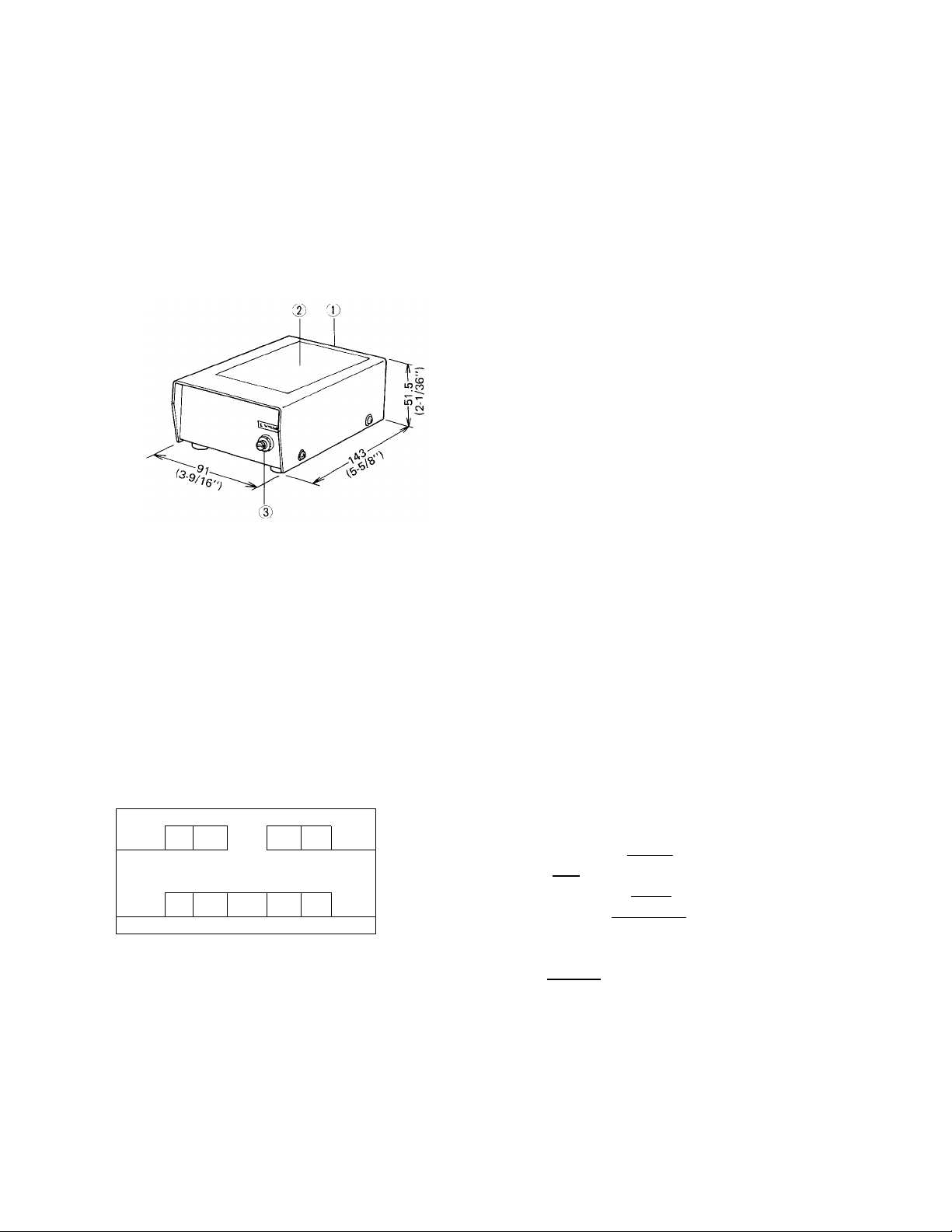
Terminal block
Connecting instruction label
Volume control
833255 0283:&'
C SPECIFICATIONS
* Power output:
* Distortion:
* Current consumption:
* Input:
* Output:
* Power requirements:
3 watts.
Less than 1% at l,000Hz 1 watt output.
750mA at maximum output.
INPUT 1 (Impedance: lOK ohm) . . . lOOmV for maximum output.
INPUT 2 (Impedance: 20 ohm) . . . 600mV for maximum output.
8 ohm (8 ohm — COM)
2 ohm (2 ohm — COM)
DC-12V. Use Aiphone PS-I2A (or PS-I2C in North America) power supply.
C ACTUAL TERMINAL LOCATIONS
©
INPUT 2
©
©
-HOC-
©
E,
©
©
12V-
INPUT 1
©
©
A E. c
©
^OUTPUT-|
$)
©
2n COM
sn
* INPUT 1: for systems TB-F, TB-H,
* INPUT 2: for systems LAF, HM-7
TS-K & KAH.
& LAH-20.
INPUT I
INPUT 2
Connect to terminal of Paging adaptor; PB-1,
PG-U,PA-1 or PA-2.
Connect to I GND| terminal of PB-1, PG-U, or
I G I terminal of PA-1 or PA-2.
Connect to I No.I terminal assigned of LAF-,
HM-7 or ( YELLOW)) wire of LAN-1 in LAH-20
system.
Connect to terminal of LAF-, HM-7 or
C
BLUE )wire of LAN-1 in LAH-20 system.
OUTPUT [M]
COM
Connect to 8 ohm paging speaker.
Connect to 8 ohm paging speaker,
but ONLY WHEN installing multi
ple number of speakers (ex. Up to
four 8 ohm paging speakers).
Connect to paging speaker.
E
: Connect to [+] terminal of PS-12 A
(or PS-12C) power supply.
Q
: Connect to GEl terminal of PS-12A
(or PS-12C) power supply.
Page 2
(^FEATURES )
Allows paging announcement to relatively small room or area (where only one paging speaker is installed) in conjunction
with Aiphone paging adaptors in TB-F, TB-H & KAH systems.
Allows paging announcement to relatively small room or area (where only one paging speaker is installed) amplifying the
output of LAF, HM-7 and LAH-20 (in conjunction with LAN-1).
Talkback paging is not available in LAF, HM-7 or LAH-20 systems.
C
INSTALLATION )
Do not attempt to install PG-3 until you have read and thoroughly understood the installation procedure. Aiphone’s
warranty is void if it is installed in a manner other than described in this manual.
1)
( WIRIN^
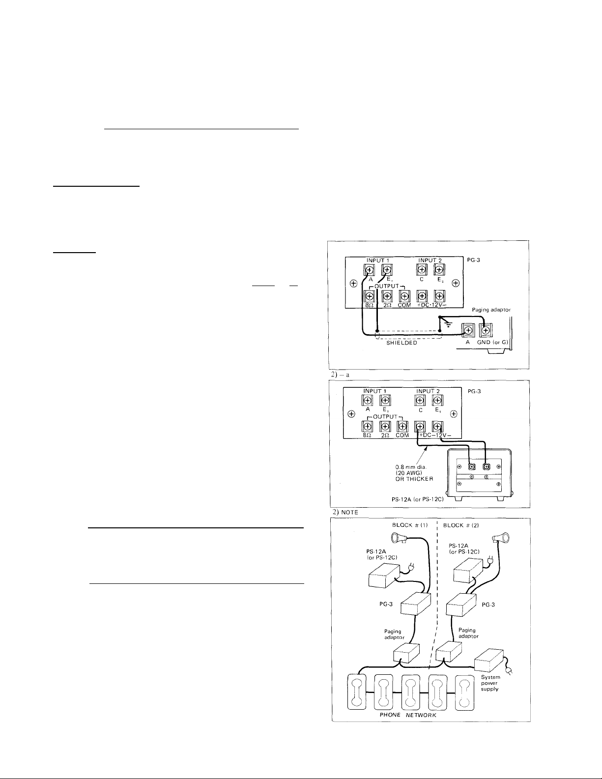
1) Amplifier input connections;
The paging adaptor and PG-3 (INPUT 1 | A | , El
terminals) should be located as close as possible to each
other. SHIELDED CABLE SHOULD BE ALWAYS USED
TO CONNECT THEM IN ORDER TO REDUCE THE
POSSIBILITY OF PICKING UP R.F. SIGNALS OR
ELECTRICAL NOISE.
2) Power supply connections;
a. PS-12 A (or PS-12C) power supply and PG-3 should be
located as close as possible to each other and 0.8 mm dia.
wires (20 AWG) or thicker should be used in order to
avoid drop of PG-3 output power.
b. LAF, HM-7, TB-F, TB-H & TS-K systems (TB-H: up to
12 phones);
One PS-12A (or PS-12C) power supply may be COMMON
LY used for both intercom system and PG-3.
c. KAH, LAH-20 & TB-H systems (TB-H: more than 12
phones);
One PS-12A (or PS-12C) power supply is required for the
intercom system and a second power supply is required
for the PG-3.
NOTE: When two or more PG-3 are installed in a system, one
PS-12A (or PS-12C) power supply MUST be used for
each PG-3.
-2-
Page 3
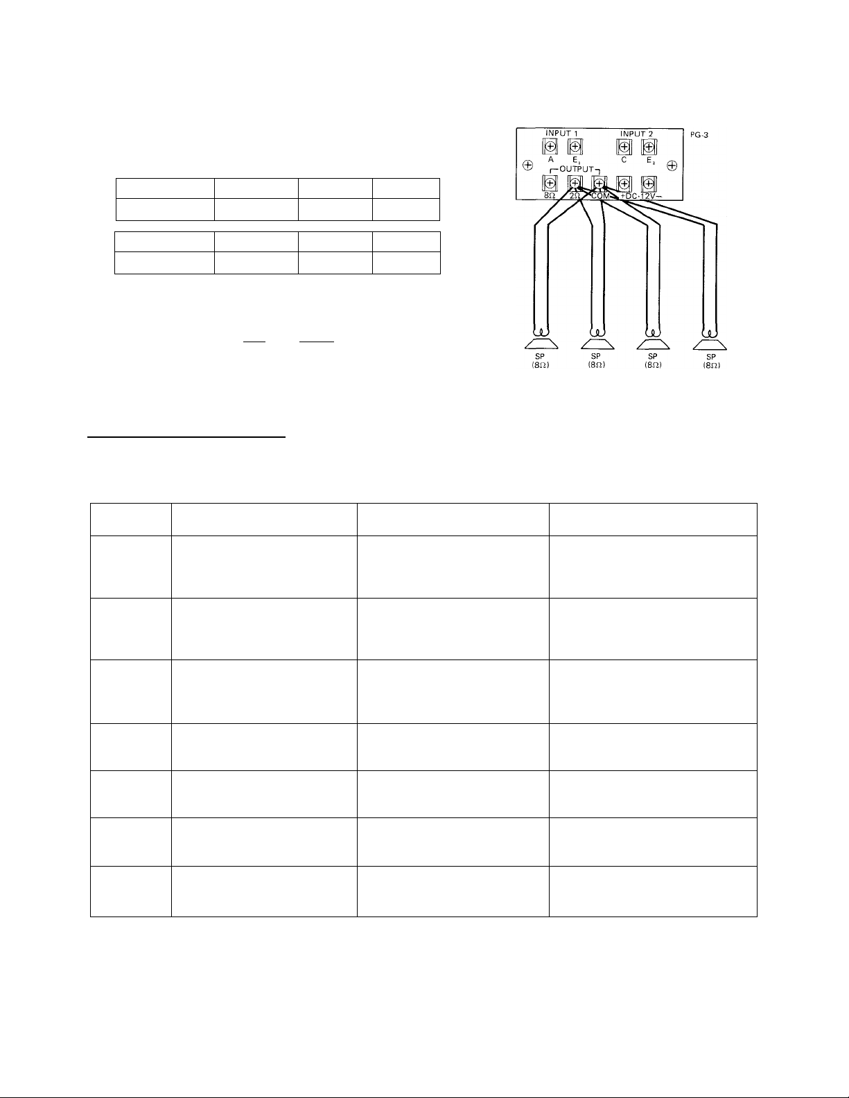
3) Paging speaker line connections;
a. Heaviest possible gauge of wires should be run from PG-3
to paging speaker.
Refer to the chart below and select the proper wire gauge
to meet your requirements.
3) -b
AWG size 22 AWG
Distance 160' 235'
Diameter 0.65 mm 0.8 mm
Distance 40 m 60 m
20 AWG 18 AWG
355'
1.0 mm
90 m
b. When paging speakers are installed in multiple (Up to four
8 ohm paging speakers are installable), run 2 separate
wires from PG-3’s |2i2[ and |COM| terminals to each
8 ohm paging speaker.
C ADAPTOR REQUIREMENT^
PG-3 can add the feature of paging to relatively small area, where one 8 ohm paging speaker is installed. The following
requirements MUST be met for paging adaptor and power supply.
SYSTEM STRAIGHT PAGING
TB-F Use PG-3 with PB-1.
TALKBACK PAGING
Use PG-3 with PB-1 and PB-2.
POWER SUPPLY FOR PG-3
Supplied by system’s single
power supply (in a system of up
to 12 phones).
TB-H
TS-K
KAH
LAP
LAH-20
HM-7
Use PG-3 with PB-1 for each
block.
Use PG-3 with PG-U for each
block.
Use PG-3 with PA-1 for each
block.
Connect PG-3 directly to
LAP stations.
Use PG-3 with LAN-1.
Connect PG-3 directly to
HM-7 stations.
Use PG-3 with PB-1 and PB-2
for each block.
Use PG-3 with PG-U and PA-B
for each block.
Use PG-3 with PA-2 for each
block.
Not available.
Not available.
Not available.
Supplied by system’s single
power supply (in a system of up
to 12 phones).
Supplied by system’s single
power supply (in a system of up
to 12 phones).
Separate power supply required
for PG-3 and system itself.
Supplied by system’s single
power supply.
Separate power supply for PG-3
and system itself.
Supplied by system’s single
power supply.
-3
Page 4

AJUSTING CONTROLS
[ 1 j When using PG-3 in conjunction with paging adaptor in systems; TB-F, TB-H, KAH & TS-K;
1. After wiring, set paging adaptor TREBLE, BASS & VOLUME controls (and, of background music source, if in
stalled) and PG-3 VOLUME control at MIDPOINT.
2. Turn on the power supply and background music source (and power supply for PG-3, if installed separately) and
proceed with adjustments in the following manner;
Test operations for paging and talkback paging, as described in the manual.
(1)
During paging, adjust paging adaptor TREBLE, BASS & VOLUME controls to desired level.
(2)
In case paging volume level is too low after paging adaptor VOLUME control is set at maximum level, adjust
PG-3 VOLUME control to achieve the most desired level.
If background music is included, adjust paging adaptor MUSIC TREBLE, BASS & VOLUME controls (or in
(3)
background music source, if included) while listening to the background music.
(4) Adjust PRE-TONE VOLUME control on paging adaptor (PB-1 only).
I 2 I
When using PG-3 in system: LAP, HM-7 & LAH;
1. After wiring, turn on the power supply (and power supply for PG-3, if installed). Set PG-3 VOLUME control at
MIDPOINT.
(1) Test operations for calling and communication, as described in the manual.
(2) Adjust master station VOLUME controls for calling and communication (LAW-1 VOLUME controls in LAH-20
system) to desired level.
(3) On master station, select the number button assigned for paging (to which PG-3 terminal is connected) and
page. Adjust PG-3 VOLUME control to desired level, while listening to the announcement from the paging
speaker.
c INSTALLATION EXAMPLES )
n~| TB-F system
(1) Straight paging
STATION I
12
<—
t™
2
^
JW
5{^
'bW
tW 7^
'aW
~2W
lOld
cV 12^4^)
TW
0®
P
^
NOTES: (1) One power supply may be used commonly,
T®
■3®
T®
8^
Ti®
c9
but lines should be run separately
from PG-3, PB-1 & TB-F phones.
(2) Depressing | P | button in handset operates
paging speaker.
SP
(8U)
(2) Paging with talkback
SP (Sill
NOTES: (1) One power supply may he used commonly,
but [+] , (3 lines should be run separately
from PG-3, PB-l/PB-2 & TB-F phones.
(2) Depressing [T] button in handset operates
paging speaker and releasing for talkback.
Page 5

fT~| TB-H system
(1) Straight paging
NOTES; (1) One power supply may be used commonly,
but lines should be run separately
from PG-3 and PB-l/TB-H phones.
(2) The selector button #6 on each TB-H phone
operates paging speaker.
(2) Paging with 2 blocks
NOTES: (1) One power supply is required for the inter
com system and a second power supply is
required for the PG-3 amplifier of each
block.
(2) The selector button #11 on each TB-H
phone operates paging speaker of block
#1 and #12 block 2.
3 LAP system
* Straight paging
STATION
1
LAP-5
NOTES; (1) PG-3 may be powered by power supply of
STATION STATION
2 3
LAP.S LAF-S
LAP system.
(2) The selector button #5 on each LAP station
operates paging speaker.
4 HM-7 system
* Straight paging
STATION STATION STATION
5 6 7
NOTES; (1) PG-3 may be powered by power supply of
HM-7 system.
(2) The selector button #5, 6 or 7 on HM-7
station #5, 6 or 7 operates paging speaker.
SP
(8n)
PS-12A (or
PS-120
- 5
Page 6

( INSTALLATION EXAMPLES ) (continued)
SP
(8n)
PS-12A (or
PS-12CI
NOTES: (1) One power supply is required for the intercom system and a second power supply is required for the PG-3.
(2) Selecting own station number buttons; i.e., #8-A on station #18, #9-A on station #19 and #10-A on station
#20 operates paging speaker.
TS-K system
(1) Straight paging
STATION'STATION STATION
5 6 7
(2) Paging with talkback
STATION 6
NOTES: (1) One power supply is required for the inter
com system and a second power supply is
NOTES: (1) PG-3 may be powered by power supply of
TS-K system.
(2) Depressing [P] button on each TS-K phone
operates paging speaker.
required for the PG-3.
(2) Depressing selector button #6 and [P]
button operates paging speaker and releasing
for talkback on each TS-K phone.
Page 7

( INSTALLATION EXAMPLES^) (continued)
KAH system
(1) Straight paging
STATION STATION STATION
10 11 12
KAH-12 KAH-12 KAH-12
NOTES: (1) One power supply is required for the inter
com system and a second power supply is
required for the PG-3.
(2) The selector button #12 on each KAH
phone operates paging speaker.
(2) Paging with talkback
STATIOM STATION STATION
10 11 12
KAH-12 KAH12 KAH-12
SP
(8iil
NOTES: (1) One power supply is required for the inter
com system and a second power supply is
required for the PG-3.
(2) Depressing selector button #12 and
button operates paging speaker and releasing
for talkback on each KAH phone.
Page 8

We at AIPHONE are proud of our products. Our designers and engineers strive to bring you the finest in communication
equipment. Each item has been carefully tested and inspected before leaving our factory. Properly installed and used, your
Aiphone intercom system should give years of trouble-free service.
We are pleased to offer the following warranty:
WARRANTY
Aiphone warrants its products to be free from detects ot material and workmanship under normal
use and service for a period of one year after delivery to the ultimate user and will repair free of
charge or replace at no charge, should it become defective upon which examination shall disclose
to be defective and under warranty. Aiphone reserves unto itself the sole r,ight to make the final
decision whether there is a defect m materials and/or workmanship: and whether or not the prod
uct is within the warranty.
This warranty shall not apply to any Aiphone product which has been subject to misuse, neglect,
accident, or to use in violation of instructions furnished, nor extended to units w'hich have been
repaired or altered outside of the factory
This warranty does not cover batteries or damage caused by batteries used in connection with the
product.
This warranty covers bench repairs only, and any repairs must be made at the shop or place des
ignated in writing by Aiphone. Aiphone will not be responsible for any costs incurred involving on
site service calls.
Aiphone Co., Ltd., Nagoya, Japan
Aiphone Corporation, Bellevue, Washington
PG-31
ALL OVER THE WORLD
AIPHONE
Printed in Japan (E)
®
 Loading...