

Page 1
LAMP MEMORY INTERCOM
Models: NEM-10/C, NEM-10A/C: 10-call master
NEM-20/C, NEM-20A/C: 20-call master
NEM-30/C, NEM-30A/C: 30-call master
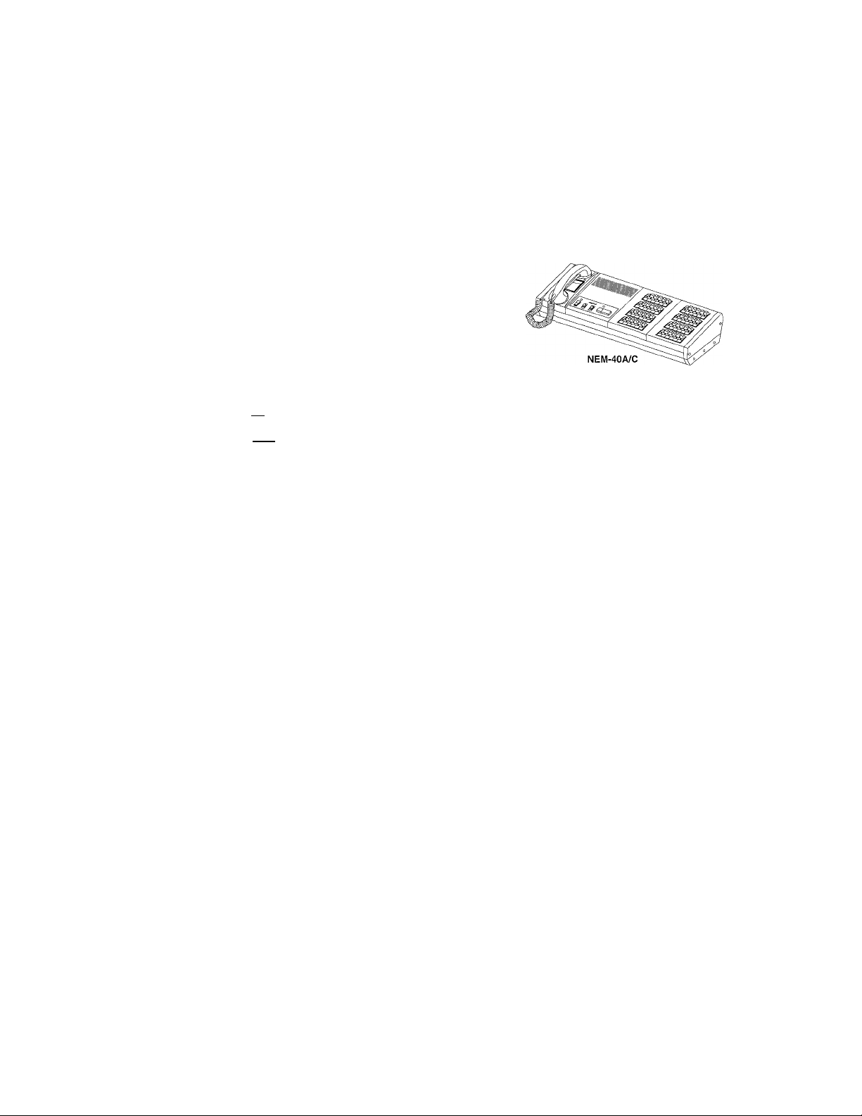
NEM-40/C, NEM-40A/C: 40-call master
INSTALLATION & OPERATION MANUAL
This Manual and the Markings on the product contain various symbols
in order that the product can be used safely and property, and that the
installer and user are protected from injury and property damage. The
following precautions must be thoroughly read and understood before
proceeding.
PRECAUTIONS ON INSTALLATION & WIRING
A\ WARNING Negligence could result in death or serious injury.
/K CAUTION Negligence could result In injury or damage to property.
83491700 0901 ©
NEM/C Series
®AIPHONE
' NEM-nA/C: w/handset
WARNING
A
1. Do not connect any power source other than
specified on NEM master. Fire or damage to
the unit could result.
2. Do not open NEM master. High voltage Is
present inside, and it can cause electric shock.
3. Do not change or alter NEM master. It can
cause fire or electric shock.
4. Make sure wires are connected properly before
plugging in power supply.
5. Keep NEM master away from water or any other^
liquid. Fire or electric shock could result.
6. Keep AC plug away from moisture or dust.
7. Keep AC cord away from being marred or
crushed.
8. Do not plug or unplug with wet hands.
9. Do not put any metal into NEM through openings,
It can cause fire, electric shock or unit damage?
CAUTION
A
. Do not make call tone testing with hook switch
manually held down. The call tone sounds very
loud near your ears, and can cause your hearing
damage.
. Do not install or make any wire terminations while
power supply is plugged in. It can cause electrical
shock or damage to the unit.
0
0
0
s>
0
3. Install NEM master in a convenient location, but ^
not where it could be bumped or jarred. V
4. In case of electrical storms, unplug power supply
from AC outlet. It can cause fire, electric shock,
or power surge damage.
5. Do not install NEM components in any of the
following locations, as it may cause the system to
malfunction;
- High or extreme cold temperature area:
under direct sunlight, near equipment that varies in
temperature, in front of air conditioner, inside a
refrigerated area, etc.
- Places subject to moisture or humidity extremes. I
- Places subject to environmental conditions,
such as oil, dust, chemicals, salt, etc.
- Places subject to constant vibration or impact.
- Places where noise generating devices such as
TV or radio are close by.
GENERAL PRECAUTIONS
A
1. NEM equipment is designed for indoor use only.
Do not install outdoors.
2. NEM system is not operational during a power failure.
3. In areas where broadcasting station antennas are close
by, intercom system may be affected by radio frequency
interference.
4. Keep ail DC wiring at least 30cm, 1' away from AC 100240V wiring, fluorescent lighting, or dimmer switches.
Otherwise, cross AC wiring at a 90° angle.
Examples of Symbols
A
GENERAL
PRECAUTIONS
GENERAL
INSTRUCTIONS
The Zimark indicates caution
statement (incl. danger and
warning), which is specifically
shown inside.
The # mark indicates contents
which demands a specific
action shown inside or attached.
0
GENERAL
PROHIBITIONS
The 0 mark indicates contents
which prohibit a specific action
shown inside or attached.
DISMANTLE PROHIBITIONS
MOISTURE PROHIBITIONS
Page 2
1 SYSTEM OUTLINE & COMPONENTS
The NEM-n/C & NEM-nA/C are master stations of Lamp Memory Intercom for
10 to max. 40 sub stations. NEM master station is capable of carrying out
communication by either open voice press-to-talk or lifting handset operation,
as well as transmit aii call to all the sub stations simultaneously.
2 -tfAp Sub stations
<, NA-A, etc.
1 common + 1 Indiv. -
To sub zone (s) ^
irZ i-
Note: For more than 40 to max. 120-station system,
SOP (*) master stations are available;
NEM-50 ~ 120, NEM-50A ~ 120A (/7.A for CE).
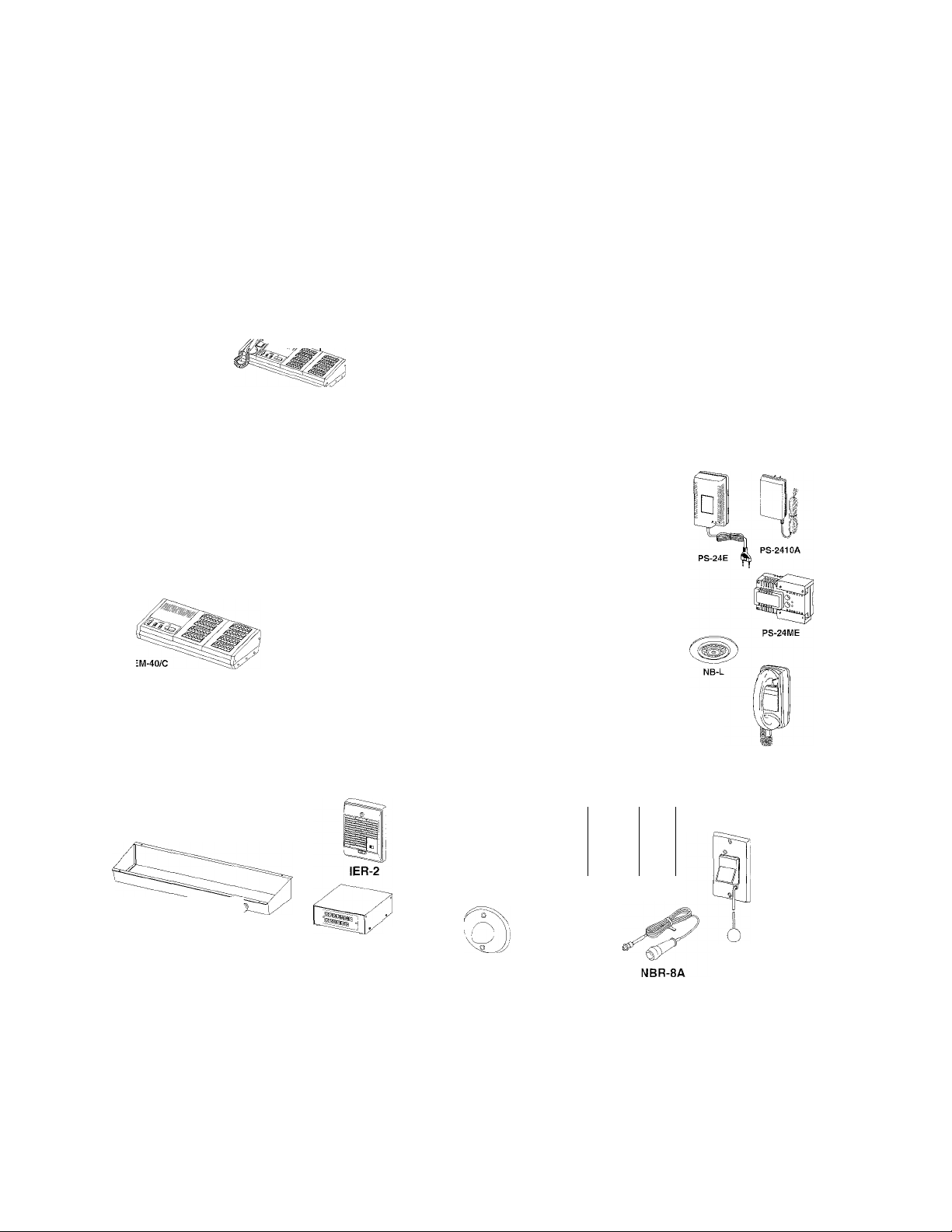
CO M PONENTS AVAILABLE
Press-to-talk master station • Master station w/handset
' i
24V DC power supply
1^]
PS-2410A (in USA, 10 ~ 20-call)
PS-24ME (in Europe, 10 ~ 20-caii)
PS-24E (10 - 40-call)
To avoid noise interference, be sure to
A
take G terminal on PS-24E to earth.
• 24V DC power supply
For up to 20 subs
PS-241 OA: 1A (120V AC)
PS-24M E: 0.9A (220V AC)
PS-24E: 2A (110V ~ 120V,
For 21 ~ 40 subs
PS-24E: 2A(110V~ 120V,
■ Sub stations
PA CKAGE CON TENTS
Master station NEM -n/C,
NEM -nA/C (n = 10, 20, 30 & 40)
Mounting hardware
Installation & Operation Manual
220V ~ 240V AC)
220V ~ 240V AC)
NEM -10/C: 10-call master
NEM -20/C: 20-call master
NEM -30/C: 30-call master
NEM -40/C; 40-call master
System options
NBJ-40B
IER-2: Call extension speaker (at NEM)
NB-U: Music adaptor. One per 40 subs.
Requires music source & amplifier.
NEW -5: Dual-call adaptor. One per 5 subs.
Requires 12V DC power supply
NBJ-20: Call switching device for
NEM-10/C &20/C
NBJ-40; for NEM-30/C & 40/C
NBJ-20B: for NEM-10A/C & 20A/C
NBJ-40B: for NEM-30A/C & 40A/C
NEM -10/VC:
NEM -20A/C:
NEM -30A/C:
NEM -40A/C;
10-call master
20-call master
30-call master
40-cail master
Health Care accessories
NB-U
NBY-4A:
NR-4AS13;
NAR-3:
NAR-6A;
NBY-1A
NBR-8A:
NBR-7AS:
NBR-7AS-S:
NBY-4A
NAR-3
NA-A
NA-A: Desk/wal, single-gang
NA-AN : w/PRIV. button
NA-NE: Flush aluminum panei
NB-L: Ceiling mount
NA-T/A: Handset sub, single-gang
NA-AN
NA-NE
o
NAR-6A, black
(3
NAR-2A, white
Corridor call light, single-gang (for up to 3 subs)
same (for 4 to max.8 subs) (SOP) [-► See P.10]
Round bracket
Flush call button plate, single-gang
Flush metal jack plate, single-gang
Bedside manual call switch
Moisture resistant pullcord, single-gang
same (for use in a patient room) (SOP) [-►See P.8]
NBY-1A
NBR-7AS
* NAR-3: Not available in USA
NR-4AS13, NBR-7AS-S: Not available in Europe
SOP (Special Order Product)
2 -
Page 3
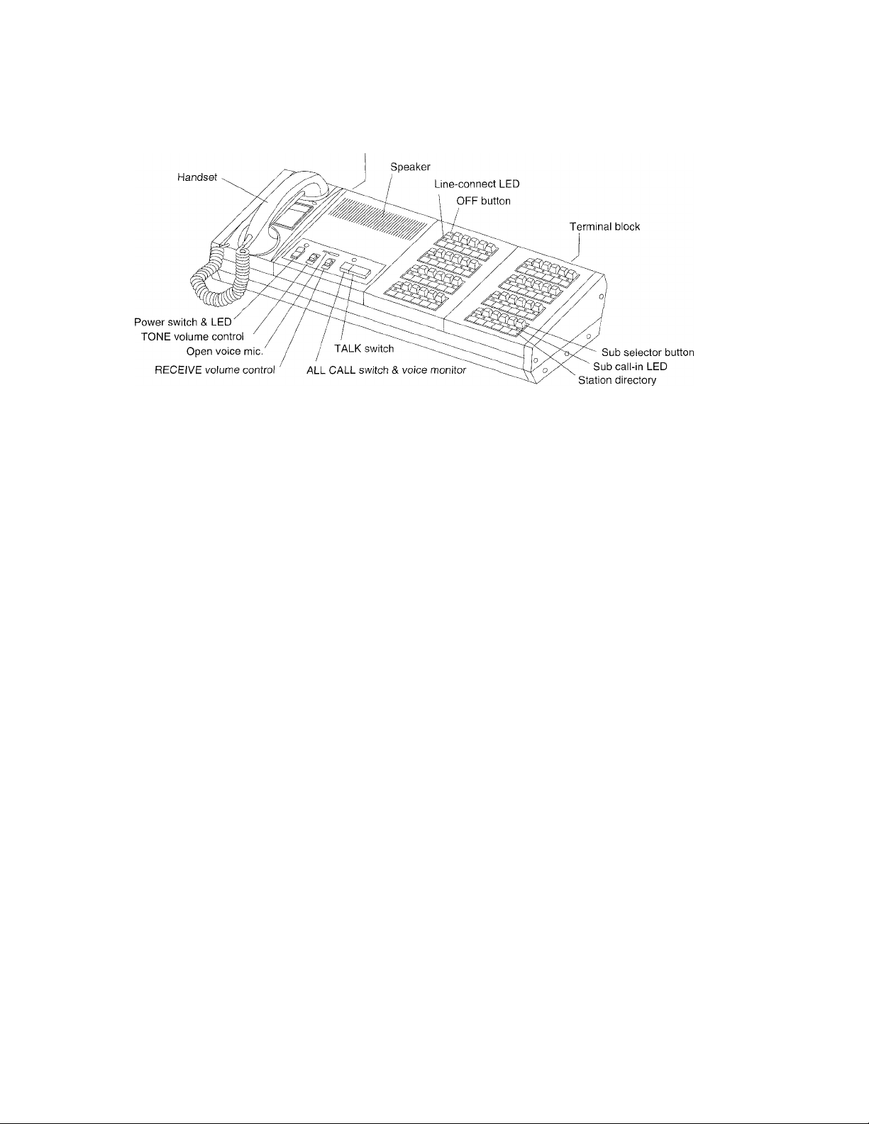
2 NAMES & FEATURES
NEM-40A/C
Preset volume controls
Handset
Power switch & LED
TONE volume control
Open voice mic.
RECEIVE volume control
TALK switch
ALL CALL switch &
voice monitor
Station directory
Sub call-in LED
Sub selector button
Preset volume controls
Speaker
Line-connect LED
OFF button
Terminal block
Used for private communication (voice-actuation)
Keep powered status, othenwise calling becomes inoperational
Adjusts sub’s call-in tone in 3 positions
Mic. is on in open voice mode
Adjusts receive volume in 3 positions
Used for open voice communication with NA sub or ail call for max. 10 selected NA subs
Instantly, activates all sub station speakers. Hold down to transmit.
Fill in name by oil-soluble pen
Upon CALL button pushed at sub, LED is steadily lit to indicate, sounding audible tone
In both initiating and receiving a call, depress a button to establish the channel
Preadjusts volumes of all call, transmit, receive & tone.
Call tone rings, and hears sub's voice
Lit during communication
Disconnects a channel of sub, and puts system in standby
Wires all sub station speakers and optional accessories
FEATURES
10 to 40-station call systems
Handset auto voice actuation and/or press-to-taik communication
Tone & LED call-in, staying until master answers
Built-in All Call
Multiple subs call, selectively up to 10 subs
Pre-tone at sub as attention-getter upon selected
Minimized crosstalk, and secured voice volume
Two conductor per sub, home run or multi-conductor cable run
Call extension speaker IER-2
Accessories for health care applications
Music distribution through sub stations. Requires NB-U adaptor, 10W amp. & music source
Call switching device to route any sub call-in to the NEM master station on duty
Sub station can call dual NEM masters simultaneously
3-
Page 4
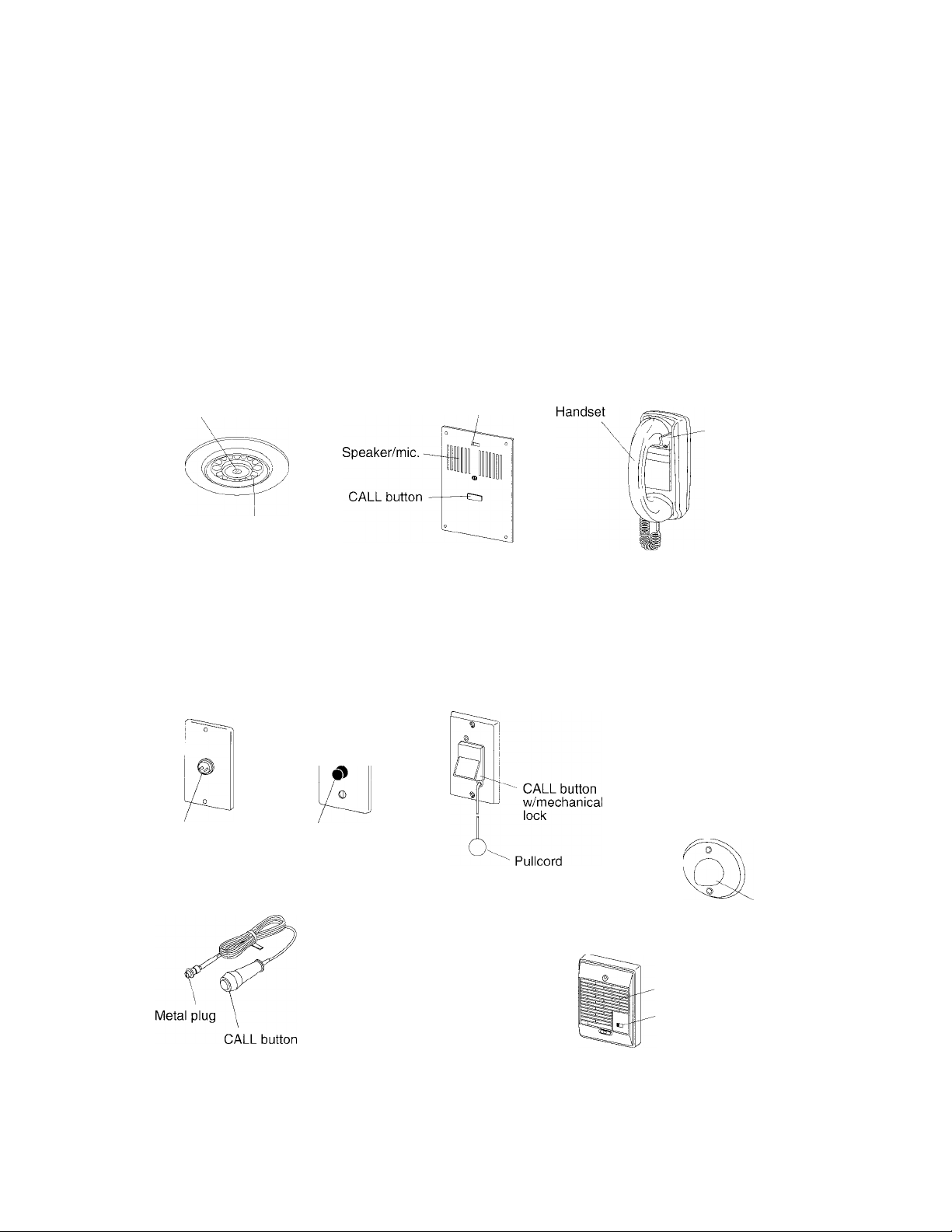
3 NAMES & FUNCTIONS
Sub stations
NA-A Desk/wall mount sub station
Speaker/mic.
Master RING
LED
NB-L Ceiling sub station
Master RING LED
Speaker/mic.
NA-AN Privacy sub station
CALL button
NA-NE Flush mount sub station
Master RING LED
Speaker/mic.
Master RING
LED
PRIV. switch
NA-T/A Handset sub station
CALL button
Handset cradle
Accessories
NBY-1A
Flush metal
jack plate
Metal jack
NBR-8A
Bedside manual
call switch
NAR-6A
Flush call
button plate
CALL button
(black)
NBR-7AS: for common area restroom
NBR-7AS-S (SOP): for use in a patient room
Bathroom puilcord call switch
NAR-2A
Call reset button
RESETbutton
(white)
NBY-4A: for up to 3 subs
NR-4AS13 (SOP): for 4 ~ 8 subs
Corridor call light
NAR-3 (*)
Round corridor call light
IER-2
Call extension speaker
Speaker
. Tone volume control
(*) NAR-3: Not available in USA
NR-4AS13, NBR-7AS-S (SOP): Not avaiiabie in Europe
Red light
Red light
- 4
Page 5
4 INSTALLATION
SYSTEM COMPOSITION
The NEM-n/C & NEM-nA/C can be composed into the following systems with the optional accessories.
NEM intercom communication
Health care communication
Call switching device
Dual master call
Music distribution to NA subs NB-U adaptor distributes background music to NA subs
COMMUNICATION
After depressing a sub selector button, depress TALK switch to transmit or release to listen. On NEM-A/C
only, lift handset and communicaiton will be automatic activation. Speak into the handset, and NEM transmits
voice. Quit speaking, and NEM turns to receive mode.
STATION SELECTION
1. Sub station: NA-T/A handset can be used alone or attached the other sub station.
2. NEW-5 dual call adaptor Is not useable with in NB-U used system.
System consists of NEM master and sub stations as needed.
Each sub station is connected with a corridor call light & reset
button. Ceiling sub NB-L is combined with bedside call switch.
Any sub's call-in received by one NEM, can be rotated
to the other NEM on duty.
NEW-5 adpator enables up to 5 sub stations to ring two
NEM's simultaneously, install multiply NEW-5's with
a 12V DC power supply.
in conjunction with music source & an appropriate amplifier.
POWER SUPPLY
WIRING METHODS
Lay out your NEM system in advance. Determine the locations of each NA sub station and wire to each.
Two conductors are required per sub station.
1. Two wires from each sub station to NEM terminal block.
2. Two wires from each sub to a local junction box, then multi-conductor cable to NEM teminai block.
3. Use a multi-conductor cable looped through each sub.
IMPORTANT: When a multi-conductor cable is not used, be sure to run each cable in the same conduit,
in order to make each sub station line as near the common line as possible.
1.
NEM-10/C
/(T •
NEM-20A/C
MOUNTING LOCATIONS
1. Select a mounting location which meets the following criteria:
- is free from dust, vibration, - is not near heating or air conditioning equipment,
- does not have temperature/humidity extremes, - run in not bare wires on floor subject to
be pinched by furniture, etc., - is not near inflammable or chemical products.
NONE OF THE SYSTEM COMPONENTS IS EXPLOSION-PROOF TYPE.
2. NBR-7AS bathroom pullcord is moisture-resistant, but not water-resistant.
Avoid such location as near bathtub, etc. where it could receive shower directly.
3. NA-NE is not weather-resistant. Do not install outdoors.
Master stations
NEM-10/C, NEM-20/C
NEM-10A/C, NEM-20A/C
NEM-30/C, NEM-40/C
NEM-30A/C, NEM-40A/C
/j\ Do not connect two power supplies in parallel.
NA-A
2.
NEM-40A/C
Power supply
PS-241 OA (24V DC, 1A)
PS-24ME (24VDC, 0.9A)
PS-24E (24V DC, 2A)
PS-24E (24V DC, 2A)
Junction box
----- -
J
a
ea. 2
ea. 2
NA-A
Page 6

TERMINAL IDENTIFICATIONS
Back panel
: Connect to sub station
1 ~ 40
E
*1)S, S(orS, EJ
Q, H, Y, E
XI ~ X8
(*2) B, Y ; Connect to NB-U adaptor
VI ~ V4
A1 ~ A4
Connect to IER-2 call extension
Connect to NEW-5 adaptor
Unused (for add-on selector)
•+, — : Power supply (24V DC)
(*1) S, E: in NEM-10, 20(A)/C
(*2) B, Y: same terminal
NEM-10/C, NEM-20/C
NEM-10A/C, NEM-20A/C
® \ Q ' H X8
B ■ Y Vi ''a- Vs A?]
SUB STATION TERMINAL & WIRE IDENTIFICATIONS
NA-A or NA-AN
Add call button
Connect two blue wires to A, B on NA-A,AN,
When corridor call light is installed
Remove a jumper D - E on NA-A,AN.
Add call button
Connect two blue wires to Orange, Org/whit
wires on NA-NE.
When corridor call light Is installed
Remove a jumper GREEN BLACK on NA-NE.
NEM-30/C, NEM-40/C
NEM-30A/C, NEM-40A/C
X8 X7 X6 X5 X4 X3 X2 X1
NA-NE NB-L
When corridor call light is installed
Cut out a jumper GREEN on NB-L.
=(^
10 9 8 7 6 5 4 3 2 1 |(i)
®
20 19 18 17 16 15 14 13 12 11 |
NEM
E
Red —^
Green
Orange
Org/whit-
- Blue NBY-4A
-Blue NAR-2A
Blue's NBY-1A
NA-T/A
NA-T/A sub station receives a pre-tone
and voice transmission from NEM
master station. For full 2-way
communication, lift NA-T/A handset.
When NA- open voice sub station is
combined, NA-T/A handset disables
the NA sub station.
Adding NA-T/A handset to NA sub station
- 6
Page 7

5 WIRING DIAGRAMS
Basic master to sub system
Sub stations
Master station
NEM-40A/C
t common + no. of subs
1 common + no. of subs
Sub stations
At ail NA sub stations, link or jumper remain attached.
2-f
■V ■■■
NA-AN
4
iji]
NA-NE
4
■Ji
Red —'
Orange
Org/whit
Blue
Green
Black -
m
S
@
Do not connect two power
supplies in parallel.
A
B
C
D
NOTES
1. Wiring: 2 wires per sub (in same jacketed cable)
2. Terminai E (max. 10) may be used for one to max. 3 wiring biocks.
3. Cali extension: One IER-2 per NEM
4. Any NA sub station may remain equipped with a link or jumper wire.
ISSl : PS-2410A, PS-24ME(forupto20subs).
/j\ To avoid noise interference, be sure to take G terminal on
PS-24E (for 1 ~ 40 subs).
PS-24E to earth.
ill
il
ll
■fill
Red-^
Orange
Org/whit
Blue
Green
Black —
7 -
Page 8

5 WIRING DIAGRAMS (co nt in ue d)
Health care applications
Sub stations
NB-L
Bathroom Pullcord
in a Patient Room
NBR-7AS-S
(SOP)
Red
•Black
5
Green "
Blue
Orange
Si
NA-A,
NA-AN
NA-A
NA-AN
Remove the link.
Do not connect two power
supplies in parallel.
NBY-4A
Blue (2)
NAR-2A
NB-L: Cut GREEN jumper when corridor light is connected.
NBY-1A: Connect NBY-1A jack plate to NB-L as required,
as long as insulator resistance is not lowered to less than 20 Ohm.
Bathroom pullcord in a patient room; Instead of NBR-7AS,
employ NBR-7AS-S bathroom pullcord (SOP), which cuts off
the NB-L mic. when NEM master selects the corresponding
selector button.
Up to three NBR-7AS-S can be connected, paralleling each
BLACK, RED & ORANGE wires. Call-in from NBR-7AS-S cannot
be cancelled with NAR-2A Call reset button. Go to the calling site,
and press on upper end of Call button on NBR-7AS-S to release
the call.
: PS-2410A, PS-24ME (for up to 20 subs).
PS-24E (for 1 - 40 subs).
/t\To avoid noise interference, be sure to take negative
{-) terminal on PS-24E to earth ground.
-8
SOP (Special Order Product).
Page 9

NA-T/A
NBR-7AS
NAR-2A
4. NBR-7AS: Up to three NBR-7AS can be connected, paralleling
each BLACK, RED & BLUE wires. (Separate BLACK & GREEN).
5. NR-4AS13: When 4 to 8 NBR-7AS are used, employ NR-4AS13
for corridor call light.
9 -
Page 10

5 WIRING DIAGRAMS (continued)------------------------------------------------------------------------------------------
Multiple sub stations in a patient room
Max. 8 NA sub stations can be installed within a patient room. For corridor call light, use NBY-4A for up to 3 subs,
and NR-4AS13 (SOP) for 4 to max. 8 subs.
Selector number must be applied to individual sub stations.
' Install NR-4AS13 (SOP) for 4 to max. 8 subs. ' Install NBY-4A for 1 to max. 3 subs.
10-
Page 11

Connecting NBJ-/NBJ-B Call Switching Device
The NBJ-/NBJ-B is a Cali switching device, which can be used to control nurse calls at two locations.
There are two possibilities in NBJ-/NBJ-B application;
1. Switching to route cails on Master #2 to Master #1;
NA-A,
NA-AN
NA-A,
NA-AN
NA-A,
NA-AN
Master #1
NEM-40A/C
NEM-40A/C
NBJ-20B
Master #2
NEM-20A/C
on NBJ>20B
11
: 24V DC power supply
Page 12

2. Switching from muitipie NEM locations to a grand NEM master;
Master #1
Master #2
Page 13

NB-U music distribution
Music distribution to NA sub stations is an additional option to NEM system.
Use an NB-U adaptor in conjunction with a 10W amp. & music source.
Music adaptor
NEM-40A/C
NB-U
¡A1
i
VI
I A2 •
I
V2 •
A3
: V3
A4 •
V4 •
Music source
NA sub stations: Duai master call application
Dual-call sub stations
NA-A (any)
! A1
^ V1
A2
• V2
A3 I
V3 I
A4 !
V4
Dual-master call adaptors NEW-5
for subs 1-5
for subs 6 ~ 10
« I
Notes;
Remove a jumper on An, Vn per 10 NA sub station
increment.
Example;
• Terminals A1,
• Terminals A1,
• Terminals At,
• Terminals A1,
V1 used forNEM-10(A)/C
V1 ~ A2, V2 used for NEM-20(A)/C
VI ~ A3, V3 used for NEM-30(A)/C
VI ~ A4, V4 used for NEM-40(A)/C
Dual-call sub stations
NA-A (any)
NEM-40A/C
13=^
Q
A\
Do not connect two power
supplies in parallel.
11
12
13
14
15
36
37
38
39
40
0
MA
MB
NEM-40A/C
MA
PS-12A, PS-12B,
PS-12C or PS-12M
PS-2410A, PS-24ME (for up to 20 subs).
PS-24E (for 1 ~ 40 subs)
/4\To avoid noise interference,
0
0
Do not connect two power
supplies in parallel.
0
12V DC power supply
be sure to take G terminal
on PS-24E to earth.
- 13-
Page 14

6 MOUNTING -
NEM- master station
NEM master station is placed on
desk-top and install an appropriate
power supply within proximity of the
NEM console. Plug the power supply
into an AC outlet provided.
NB-L
A\
To avoid noise interference, be sure to
take G terminai on PS-24E to earth.
NBY-1A
NAR-2A,
NAR-6A
bracket
Single-gang box
83.5mm
{3-5/16")
Single-gang box
83.5mm
(3-5/16")
NAR-3
Round gang box
66.7mm
(2-9/16")
* NAR-3; Not available in USA
- 14
NBR-7AS
NBR-7AS-S
guided
Single-gang box
Page 15

7 OPERATIONS
TURN ON POWER SWITCH.
Plug the power supply Into AC outlet.
Turn on the power of NEM.
The LED above illuminates to indicate.
The NEM must be always in powered
status.
Calling an NA sub
Receiving a call
ALL CALL
ALL CALL to selected NA subs
Health Care communication: ■
Calling from bedside
Cailing from NBR-7AS
Duat NEM master system:
Common sub call-in
Adjustments
1. Depress a sub selector button.
2. Depress TALK switch to transmit voice.
3. Release TALK switch to listen to sub.
4. At the end, depress OFF button.
1. Sub's call-in sounds an intermittent electronic
tone and lights the selector LED on.
2. Depress the lit selector button.
3. Use TALK switch to control communication.
4. Depress OFF button to disconnect the line.
1. Depress and hold down ALL CALL switch, and
speak into the mic. or lifting handset.
Voice monitor LED blinks.
2. Just release ALL CALL switch to terminate the mode.
1.
Depress 2 to max. 10 sub selector buttons, as desired.
2.
Transmit message, depressing TALK switch.
3.
To put system in standby, depress to lock all OFF buttons.
1. Momentarily press bedside call switch NBR-8A.
2. Call-in rings intermittent electronic tone and lights on a selector LED.
3. NBR-4A corridor light turns on red.
4. Depress a lit selector button, and communicate with TALK switch.
1. Press hard on nurse-marked button NBR-7AS. Or pull down cord.
2. NEM is called by intermittent electronic tone and an LED red lit.
3. Depress a lit selector button only to silence tone. Go to the calling location.
4. At the bathroom, press hard on the upper end of CALL button.
The call is reset, and corridor call light goes off.
1. Momentarily depress CALL button. Master RING LED is lit.
2. Two NEM masters ring simultaneously.
3. Either NEM depresses a lit selector button.
Pre-tone sounds at the selected NA substation.
4. Communicate.
The call self cancels at the other NEM, while Occupied LED (output monitor) Is
only lit. But, it can place a call to any other sub (crosstalk may occur).
NEM master station has daily adjust RECEIVE & TONE controls, and preset
volume controls on back panel. Only for RECEIVE volume, prior to adjusting
the back RECEIVE control, put to MID position the front RECEIVE control.
NEM front panel
RECEIVE TONE
ALL CALL TRANSMIT RECEIVE TONE
L H
L H L H L H
Page 16

8 TECHNICAL PRECAUTIONS
9 SPECIFICATIONS (NEM(-A)/C)
Operating temperatures
NEM & NEM-A master stations are rated to operate
at temperatures between 0° ~ 40°C (32 °F ~ 104°F).
Mounting iocations
The NEM equipment is not explosion proof type. Do
not install any unit In a place filled with Igniting gas.
Operation
At end of every communication, be sure to depress
corresponding OFF button, which disconnects the
sub station as well as puts system in standby.
Otherwise, call tone will not sound audibly.
When asking for repairs
When system malfunctions, do not attempt to remove
or change any unit. Call the installing dealer or
representative.
Cleaning
Clean NEM equipment with a soft cloth dampened
with neutral household cleanser. Never use any
abrasive cleaner or cloth.
Power source:
Power consumption:
Power supply:
Calling:
Communication:
Output:
All call output:
Wiring:
Cable size
Distance 130m 200m 300m
Cable size 22AWG 20AWG 18AWG
Distance
24V DC.
Max. 24W. 2W in Standby (20-call)
Max. 45W. 4W in standby (40-call).
PS-241 OA. PS-24ME (10 ~ 20-call).
PS-24E (10 ~ 40-call).
Intermittent tremolo tone and lit LED,
held until answered at master.
Pre-tone and voice at sub.
Open voice, press to talk or handset
voice-actuation
Max. 500mW at NEM (w/adj.
RECEIVE vol.)
Max. 500mW at sub (w/adj.
TRANSMIT vol.)
6W (up to 20 subs)
2W (21 to 40 subs)
3W (per 10 subs random selected)
2 wires per NA sub station
(1 for common E line).
0 0.65mm 00.8mm
420' 650' 1,000'
Dimensions & weight:
H w D Weight (approx.)
NEM-10/C
140
X
346 X 260
NEM-20/C 140 X 346 X 260
NEM-30/C
140
X
496 X 260
NEM-40/C 140 X 496 X 260
NEM-10A/C 176
X
446 X 260
NEM-20A/C 176 X 446
NEM-30A/C 176 X 596 X 260
NEM-40A/C 176 X
NEMtIO/C
NEM-20/C
NEM-30/C
NEM-40/C
NEM-10A/C
NEM-20A/C
NEM-30A/C
NEM-40A/C
5-1/2 X
5-1/2 X
5-1/2
5-1/2 X
7" X
7"
7" X 23-1/2" X 10-1/4"
7"
596 X 260
13-5/8'
13-5/8'
X 19-1/2' X 10-1/4"
19-1/2' X 10-1/4"
17-5/8'
X 17-5/8' X 10-1/4"
X 23-1/2' X 10-1/4"
X 260
X 10-1/4"
X 10-1/4"
X 10-1/4"
01.0mm
4/5Kg.
5.0Kg.
6.5Kg.
7.0Kg.
5.5Kg.
6.0Kg.
7.5Kg.
8.0Kg.
9.92 lbs.
11.02 lbs.
14.33 lbs.
15.43 lbs.
12.13 lbs.
13.23 lbs.
16.53 lbs.
17.64 lbs.
t WARRANTY
4- Aiphone warrants its products to be free from defects of material and workmanship under normal use and service
^ for a period of one year after delivery to the ultimate user and will repair free of charge or replace at no charge,
* should it become defective upon which examination shall disclose to be defective and under warranty. Aiphone
4- reserves unto itself the sole right to make the final decision whether there is a defect in materials and/or
j- workmanship; and whether or not the product is within the warranty.
If This warranty shall not apply to any Aiphone product which has been subject to misuse, neglect, accident, or to
4- use in violation of instructions furnished, nor extended to units which have been repaired or altered outside of the
j- factory.
j This warranty does not cover batteries or damage caused by batteries used in connection with the product.
4. This warranty covers bench repairs only, and any repairs must be made at the shop or place designated in writing
by Aiphone. Aiphone will not be responsible for any costs incurred involving on site service calls.
AIPHONE CO., LTD., NAGOYA, JAPAN
AIPHONE CORPORATION, BELLEVUE, WA, USA
AIPHONE EUROPE NV, ANTWERP, BELGIUM
®AIPHONE
Providing Peace of Mind
NEM/C-I(E) 0901F
- 16-
Printed in Japan (E)
 Loading...