

Page 1
Special
Order
Products
MYW-MD/B
Video Modulator/Demodulator for MK and MY Series Video Systems
- INSTRUCTIONS -
The MYW-MD/B adaptor converts the video from a 2-wire signal to a standard coaxial video signal
(Demodulator mode). It can also be used to convert a standard CCTV camera's signal to a 2-wire signal
(Modulator mode).
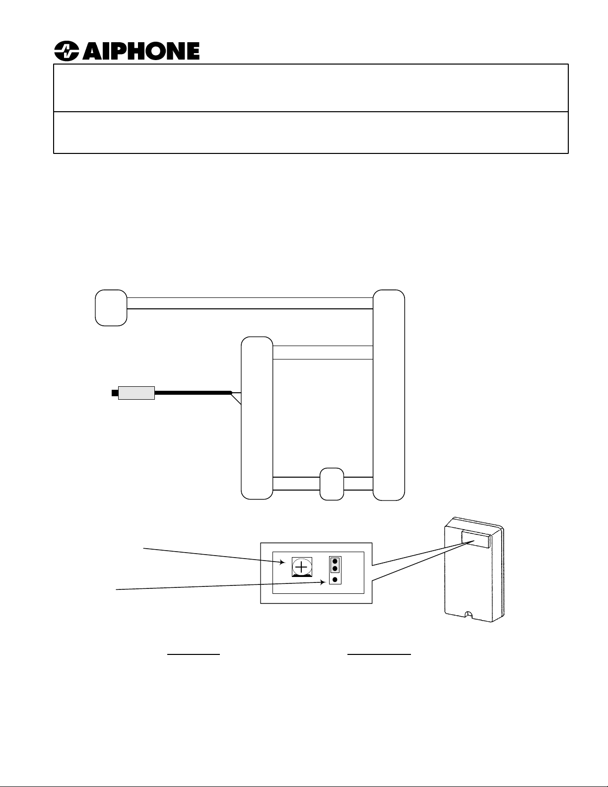
MODULATOR
MYW-MD/B to integrate a Standard CCTV camera with an Aiphone Monitor
The MYW-MD/B is compatible with Aiphone's MK and MY series video monitors.
MK-DBC
A1
A2
MY-2CD*
1A1
1A2
MYW-MD/B
MA1
CCTV Camera
75 Ohm, 1V Peak-to-peak
(Independently powered)
Center cond. to MV+
Braid to MV-
MA2
MV+
MV-
+
-
JUMPER CLIP AND DEVIATION CONTROL:
Located under rubber cover in upper right corner of the faceplate of the MYW-MD/B.
DEVIATION CONTROL:
To increase contrast, turn clockwise
with a small screwdriver. Only applicable when
MYW-MD/B is used in Modulator mode. (See pg 4)
JUMPER CLIP:
Set in Modulator (top) position from factory. Ensure
that jumper clip is between the top two pins.
Polarized
PS-1820UL
+
-
2A1
2A2
*MYW-MD/B Can also be used with:
MK-1MD/A
MY-1CD
MY-CU
MYW-P1L
MYW-P3L
B1
B2
+
-
MYW-MD/B TERMINAL DEFINITIONS:
MODULATOR:
MA1 2-Wire output to
MA2 MY monitor/adaptor
MV+ Coax input: center cond.
MV- Coax input: Braided shield
+ Positive 18V DC
- Negative
Input signal requirements:
75 ohm, 1V peak-to-peak.
Coax: Solid copper core with copper braid.
DEMODULATOR:
DA1 2-Wire input from
DA2 MK or MY monitor/adaptor
DV+ Coax output: center cond.
DV- Coax output: Braided shield
+ Positive 18V DC
- Negative
Output signal:
75 ohm, 1V peak-to-peak.
Coax: Solid copper core with copper braid.
Pg. 1
Page 2
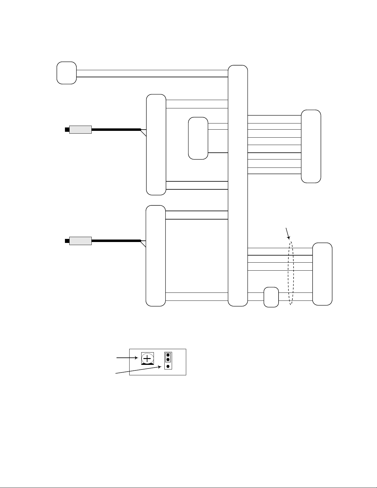
MODULATOR
Master Sentry Intercom and Video System with Standard CCTV Cameras
MK-DBC
A1
A2
CCTV Camera
75 Ohm, 1V Peak-to-peak
(Independently powered)
Center cond. to MV+
CCTV Camera
75 Ohm, 1V Peak-to-peak
(Independently powered)
Center cond. to MV+
Braid to MV-
Braid to MV-
MYW-MD/B
MA1
MA2
MV+
MV-
+
-
MYW-MD/B
MA1
MA2
MV+
MV-
Polarized
LE-DA*
1
E
-
* Any LE or LS series
door station may be used.
Polarized
MYW-P3L
1A1
1A2
2A1
2A2
DA
DB
E
R
12+
12-
EL2
KA
KB
18+
18-
3A1
3A2
B1
B2
U1
U2
LEF-10C*
10
9
E
R
12+
12-
L
K10
K9
* Any 5 or 10 call LEF
series master can be
used.
Separate video cable from
intercom cable
MYH-CUB*
A1
A2
U1
U2
+
-
JUMPER CLIP & DEVIATION CONTROL:
under rubber cover in upper right corner of the faceplate of the
MYW-MD/B.
To control contrast, adjust
with a small screwdriver.
Ensure that jumper clip is
between the top two pins.
System Configurations:
1 Aiphone video door station and 2 CCTV cameras
or
2 Aiphone video door stations and 1 CCTV camera
Optional:
Part #261380 - Video Output connector for MYW-P3L.
(Provides a 1V peak-to-peak video signal output when
the Aiphone monitor is on.)
Located
PS-1820UL
18+
18-
NOTES:
1. In the above system example, the CCTV
cameras are addressed by pressing the
MONITOR button on the MYH-CUB. Press once
to turn on camera 1 (MK-DBC), press again to
switch to camera 2 (CCTV #1). Pressing
MONITOR a third time will switch to Camera 3
(CCTV #2), and a fourth time turns the monitor
off.
2. The LE-DA will become active by selecting
station #9 on the LEF-10C. Selecting this station
will also activate CCTV camera #2. The camera
will not activate when the LE-DA calls in.
ONLY WIRING CONCERNING THIS APPLICATION
IS SHOWN HERE. SEE PRODUCT INSTRUCTIONS
FOR COMPLETE WIRING INFORMATION.
+
-
* Use MYH-CU for surface
mount applications.
+
-
Pg. 2
Page 3

DEMODULATOR
MYW-MD/B used for VIDEO OUTPUT with Aiphone MK or MY series Video Entry Systems
The picture from the Video Door Station can be seen on standard monitors whenever the Aiphone system
is activated.
MK-DS or
MK-DBC
A1
A2
MK-1MD/A
or MY-1CD
1A1
1A2
Polarized
MYW-MD/B*
DA1
DA2
* Used for video OUTPUT with
MK-1MD/A, MY-1CD, MY-CU,
MYW-P3CB, MYW-P1L, and
MYW-P3L.
DV+
DV-
Center cond. to DV+
Braid to DV-
Coax output to standard video
input. (CCTV monitor, RF
modulator, or into cable
distribution network through a
multiplexer.)
Variable Capacitor
Factory
setting. Adjust
counter-clockwise
for MK series, or
as needed for for
better image.
PS-1820UL
+
-
+
-
+
-
JUMPER CLIP: (Located under rubber cover in upper
Video Output Control:
Using a small screwdriver,
adjust the Video Output
Control to obtain the correct
level for the CCTV device
you are using.
right corner of the faceplate of the MYW-MD/B)
Move to Demodulator (lower) position.
Ensure that jumper clip is
between the bottom two pins.
DEMODULATOR
MY Video Door Station with Standard Monitor (No audio communication or PanTilt capabilities)
MK-DBC*
*Any MK
series
camera can
be used
JUMPER CLIP: (Located under
rubber cover in upper right corner of
the faceplate of the MYW-MD/B).
Move to Demodulator (lower)
position.
A1
A2
Ensure that jumper clip is
between the bottom two pins.
TO POWER THE CAMERA:
(1) WHEN IN USE
- Install a switch or relay contact in series with the "+" terminal from the power supply (see diagram.)
- Solder a jumper between points labeled AA on the MYW-MD/B main PC board. (see illustration)
This allows the camera to be activated manually, or when the relay contact is activated from a separate
source.
(2) CONTINUALLY
- Solder a jumper between points labeled AA on the MYW-MD/B main PC board. (see illustration)
This will provide continuous power to the camera, which may cause the camera to be warm.
Note: Continually powered, the overall life of the camera will be reduced and condensation may occur.
ADJUSTING THE OUTPUT SIGNAL:
Using a small screwdriver, adjust the Video Output Control to obtain the correct level for the CCTV device you
are using.
IMPORTANT:
CN2 speaker microphone
connector inside Aiphone
Video door station must be
unplugged to prevent the
possibility of feedback.
PS-1820UL
+
-
MYW-MD/B*
DA1
DA2
DV+
DV-
+
-
To standard monitor
or monitor input on a
video switcher.
Center cond. to DV+
Braid to DV-
Solder jumper
wire between
two holes in
land pattern.
Standard 9"
Monitor
AA
Solder side
view of PC
board.
Pg. 3
Page 4

IMPORTANT:
Modulator Deviation Control:
applies only when the MYW-MD/B is used with a CCTV camera. To adjust the picture for more contrast, turn the variable
resistor clockwise with a small screwdriver. (See page 1.)
Contrast control located underneath the cover in the upper right corner of the unit. This
OPERATIONS
MODULATOR:
Using the MODULATOR to Integrate a CCTV camera with an Aiphone 2-wire video system:
1. The view from the CCTV camera can be seen on the Aiphone MY monitor by pressing the MONITOR button. With
multi-camera systems (MY-2CD, MYW-P3CB & MYW-P3L), the cameras will come up sequentially. (e.g. One
press of MONITOR button brings up camera 1, second press brings up camera 2.) After the last camera in the
system is activated, the next press of the MONITOR button will turn off the monitor. If the monitor is left on, it will
automatically time out after 2-½ minutes.
2. When using a CCTV camera with the LEF/MY system, an audio sub station can be installed near the camera to
provide audio monitoring. The sub station and camera are activated simultaneously from the LEF master station
through the connection of the "K#" terminal from the LEF to the MYW-P3L adapter.
DEMODULATOR:
Using the Demodulator for VIDEO OUTPUT with the Aiphone 2-wire video systems:
1. When the call button is pressed on the MK door station, the inside monitor station will ring and the picture will
activate. At that time, the video signal out of the MYW-MD/B adaptor will be present, and the picture can be seen on
the monitor(s).
2. When the MONITOR button on the inside Aiphone station is pressed, the picture will come up for approximately
2-½ minutes and video signal will be sent to the monitor via the MYW-MD/B.
3. The video signal can be connected to any receiving device that accepts a composite video signal (75 ohm, 1V
peak-to-peak). This could be a standard CCTV monitor, a video input on a switcher or a multiplexer system that
modulates the video onto a cable TV channel. To take the video signal directly into a TV, use a spare video input
or go through the proper modulator.
Using the Demodulator to integrate the MY video door station with a standard CCTV monitor:
(No audio communication or PanTilt is possible with this application)
1. To view the camera location at any time, the camera must be powered at all times, or a switch must be installed to
turn it on. To do this, the PC board must be modified by adding a jumper wire in the location indicated on the wiring
diagram on page 3.
2. There is no PanTilt control of the camera when used in this application. To adjust the angle of the MK camera at the
time of installation, remove the Lexan® dome and move the camera head to the desired angle. Replace the dome
and install the unit.
3. If the camera is powered continually, there will always be a video output from the MYW-MD/B. There is no audio
communication possible through the door station. This application will shorten the life of the camera.
SPECIFICATIONS:
Power: 18V DC. Use Aiphone model PS-1820UL
Current consumption: 100mA as Modulator; 500mA as Demodulator
Wiring distance: ALL DISTANCES ARE USING 18 AWG WIRE
Modulator: Max. 330' from MYW-MD/B to MY Monitor/adaptor
Demodulator: Max. 30' from MK or MY monitor when used for video output
Max. 330' from MK door station when used with a standard monitor
Power supply: Max. 16' to MYW-MD/B
Dimensions: 5-1/2"H x 3"W x 1-1/2"D
COAXIAL CABLE: 75 ohm, copper center conductor, copper braid, 95% coverage.
DC resistance: Max, 15
Ω
per 1000 feet.
Aiphone Communication Systems
1700 130th Ave. N.E.
Bellevue, WA 98005
(425) 455-0510
FAX (425) 455-0071
Toll Free Technical Support:
1-800-692-0200
FAX: 1-800-832-3765
E-mail tech-serv@aiphone.com
Pg. 4
MYW-MD/B Instr.
0703bkjs
 Loading...