

Page 1
83349900 0496 i
PanTilt entry security system
LONG-DISTANCE ADAPTOR
& AlPHONE
Model;
MYW-BA
INSTALLATION & OPERATION MANUAL
SYSTEM OUTLINE & FEATURES
PanTilt video system has limited its applications within a distance of 100m(330’). MYW-BA is capable of expanding
wiring distance of PanTilt door station more than 100m and up to 300m (330’ to 980’) in MY-1CD or MY-2CD
monitor station systems. Versatile TD-H/B or LEF systems, combined with MY-CU monitor, may have PanTilt door
communication systems, using each door/video adaptor.
SYSTEM LAYOUT EXAMPLE
Operates on 2 conductors to PanTilt door station
MY-1CD
300m (max.) w/1.2mm dia.
980'w/16AWG
FEATURES
☆ Works with the following PanTilt entry security systems;
MY-1CD, Video Sentry PanTilt
MY-2CD, Video Sentry PanTilt Plus
MY-CU with TD-H/B selective call system
MYH-CU with LEF-10 open voice selective call system
☆ One to max. 3 video entries. One MYW-BA is required per entry.
☆ Powered by a single power supply PS-18D(18C) of using MY
video system.
A separate power supply locates MYW-BA max. 50m (165’) away
from the monitor station.
Check the package contents before installation.
• Long-distance adaptor (MYW-BA)
• Screws pack
• Installation & Operation Manual
PS: PS-18DorPS-18C
1 unit
1 set
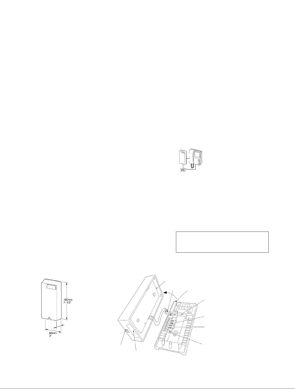
NAMES AND FUNCTIONS
42mm
1-5/8"
Front screw
Opening for
the cable
- 1
Opening for the cable
Connector
Lift and pull away
Mounts on single
gang box with 83.5mm
(3-5/16“) guide
To: inside monitor
To: PanTilt door station
To: PS-18D (18C) power supply
Do not cross wire.
Page 2
INSTRUCTIONS ON INSTALLATION & WIRING
MYW-BA is a video wiring adaptor for indoor use only.
Its mounting location must be in the same category as described in the Manuals of using video monitor.
On a specified pair wires, audio & video communication is stable and unaffected, and pan-and-tilting
operation of door camera is flexibly smooth at max. 300m (980’) distant entry.The MYW-BA performance
depends on the cable and distance to PanTilt door station and also to inside monitor (s).
The below specifications must be met for using wires on
MYW-BA adaptor;
Insulation with PE(Polyethylene)
Never with PVC(Polyvinyl chloride)
* Impedance : 90 ohm
* Permitted closed loop DC resistance :
9.9 ohm or less
* Insulation must not be PVC, but PE
In USA, cable type West Penn D990 or equivalent
* ★
Bare copper conductor pE or PVC
1.2mm for 300m
★ Installation of non-specified cable and / or within 100m (330’) or over 300m (980’) distance,
may cause inferior imaging or incomplete call.
★ While making wire terminations, front case may be set aside, plugging off connector. Refrain
from doing so, when the system power supply is turned on.
★ Wiring on MYW-BA must be strictly in accordance with diagrams on page 3, 4 & 5. Incorrect
connection of PS-18D (18C) power supply causes damage to the unit.
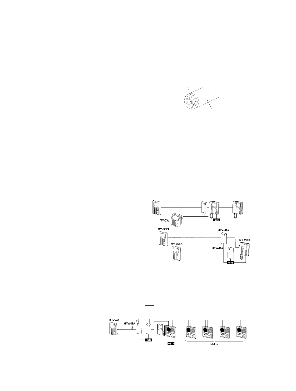
System possibilities
According to system size & station capacity required, select a best suited from the followings;
MY-1CD
Basic one-entry PanTilt system can be an important entry check
system.
MY-DC/A
MYW-BA
MY-2CD
MY-2CD monitor station control entry at 2 PanTilt door stations.
-il
Sheath
MY-CU with TD-(6,12,24)H/B
One PanTilt door,one monitor
(or two), and multiple TD-H
phone stations
MYH-CU with LEF-5,10,10S
One PanTilt door, one monitor
(or two), and multiple LEF open
voice stations
MY-DC/A
MYW-BA
2
----
liiJM-
MYW-P1L MYH-CU
AUDIO
X
ij^ I '¿M I n)u
N/-
TD-6H/B
Page 3

PanTilt MYH-CU 3-camera system with LEF-10
MYW-P3L adaptor provides LEF-10 with PanTilt door communication capabilities, including visual
checking of 3 entries, and selected entry listening with its image.
The above example illustrates 2 PanTilt door stations and an overhead viewing camera MY-CA
(in MYW-CA) are connected to 7-call LEF-10 system.
MOUNTING
Loosen a front bottom screw and open the front case, sliding front case upward from the chassis.
Unplug the connector from the chassis, and set aside the front main unit.
The chassis mounts to wall with 83.5mm, 3-5/16” pitched.
Make wire terminations on 4 screw terminals, then DC18V wires from power supply.
Reconnect and attach the front case to chassis, and tighten the bottom screw.
WIRING
MY-1CD long-distance application
MY-1CD is basic 1 door -1 monitor PanTilt system. With an MYW-BA added, MY-1CD now communicates with
PanTilt door station at gate, which is 300m(980’) away.
PanTilt door station
MY*DC/A
300m / 1.2mm dia.
980716AWG
PS-18D(18C)i
MY-2CD 2 PanTilt door long-distance application
MY-2CD matches for the system with 2 PanTilt doors. One MYH-2CD sub monitor(max. 2) may be added,
featuring same operations as on main monitor, and audio/video monitoring independently operable.
I Total of 6 conductors
(• w/2 each wires on
I 1,- terminals
Page 4

TD-H/A one PanTilt entry long-distance application
TD-H/A multiple-station is capable of connecting PanTilt door station, in conjunction with DE-UR adaptor.
For long-distance application, locate MYW-BA adaptor between PanTilt door station and MY-CU monitor.
Wiring
Single pair conductors to PanTilt door station
Single pair conductors to MY-CU main monitor
MYW-BA powered by PS-18D(18C) power supply of MY-CU video system.
Wiring distance MYW-BA to PanTilt door station
Diameter 1.0mm 1.2mm
Distance 200m 300m
A separate power supply locates MYW-BA within max. 50m/165’ distance to MY-CU monitor,
with 1.0 or 1,2mm dia. (18 or 16AWG) .while it must be power sourced separately.
AWG
Distance 650’
18AWG 16AWG
980’
■4-
Page 5

LEF-5 one PanTilt entry long distance application
MYW-P1L connects one PanTilt door to LEF-(5,10,10S) with MYH-CU video-monitor(s).
MYW-P1L MYH-CU
Wiring
Single pair cable to PanTilt door station. It is also suggested to specify the same type for wiring to monitor(s), which is
separated from LEF audio wiring.
Wiring distance MYW-BA to PanTilt door station
Diameter 1.0mm 1.2mm
Distance
MYW-BA to MYW-P1L monitor(s)
Diameter
Distance 50m
One power supply PS-18D(18C) suffices for one MYW-BA connected MYW-P1L system with one MYH-CU monitor.
Max. distance from MYW-P1L to a video monitor(farthest) is 75m w/1.0mm dia. (245’ w/18AWG).
Refer to the MYW-P1L Manual for non-MYW-BA used system examples.
200m 300m
1.0 or 1.2mm
AWG
Distance 650’ 980’
AWG 18or16AWG
Distance 165’
18AWG 16AWG
-5-
Page 6

SPECIFICATIONS
Power source
Current consumption
Cable requirements
MYW-BA; DC 18V. Can be powered by a PS-18D (PS-18C in North America) of using
PanTilt monitor system. Replaces PS-18YD/A (PS-18YC/A) in MY-ICD system.
250mA. ImA(standby)
Use specified cable to each PanTilt door station and Monitor station /video adaptor.
* Impedance ; 90 ohm
* Permitted closed loop DC resistance : 9.9 ohm or less
* Insulation must not be PVC
In USA, cable type West Penn D990 or equivalent.
Wiring
Wiring Distance MYW-BA to PanTilt door (with specified cable)
Dimensions (H x W x D)
Weight
Total 6 conductors run from MYW-BA to video trunkage line.
2 conductors to PanTilt door station and 2 to using main monitor MY-1 CD, MY-2CD or
MY-CU in TD-(6, 12, 24) H system. In LEF-(5, 10, 10S), the same 2 conductors to MYW-P (1,3) L video adaptor.
The rest 2 conductors go to the system’s power supply PS-18D (18C) or Its own.
Diameter 1.0mm 1.2mm AWG
Distance
MYW-BA to video-monitor (main) or MYW-P(1,3)L
Diameter 1.0 or 1.2mm
Distance 50m Distance
MYW-BA to power supply
Diameter
Distance
190 mm X 80 mm x 42 mm. 7-1/2" x 3" x 1-5/8"
Approx. 210 g {0.46 lbs.)
200m 300m
1.0mm 1.2mm
7m 10m
Distance 650’
AWG 18or16AWG
AWG 18AWG 16AWG
Distance 23’ 33’
18AWG 16AWG
980’
165’
This equipment has been tested and found to comply with the limits for a Class B digital device, pursuant to Part 15 of the FCC Rules. These
limits are designed to provide reasonable protection against harmful interference in a residentiai installation. This equipment generates,
uses, and can radiate radio frequency energy and, if not installed and used in accordance with the instructions, may cause harmful
interference to radio communications. However, there is no guarantee that interference will not occur in a particular installation. If this
equipment does cause harmful interference to radio or television reception, which can be determined by turning the equipment off and on, the
user is encouraged to try to correct the interference by one or more of the following measures:
• Reorient or relocate the receiving antenna. • Connect the equipment into an outlet on a circuit different from that to which the receiver is
connected. • Increase the separation between the equipment and receiver. • Consult the dealer or an experienced radio/TV technician
for help.
Aiphone warrants its products to be free from defects of material and workmanship under normal use and servioe for a
period of two years after delivery to the ultimate user and will repair free of charge or replace at no charge, should it
become defective upon which examination shall disclose to be defective and under warranty. Aiphone reserves unto itself
the sole right to make the final decision whether there is a defect in materials and/or workmanship; and whether or not the
product is within the warranty.
This warranty shall not apply to any Aiphone product which has been subject to misuse, neglect, accident, or to use in
violation of instructions furnished, nor extended to units which have been repaired or altered outside of the factory. This
warranty does not cover batteries or damage caused by batteries used in connection with the product.
This warranty covers bench repairs only, and any repairs must be made at the shop or place designated in writing by
Aiphone.
Aiphone will not be responsible for any costs incurred involving on site service calls.
Aiphone Co., Ltd., Nagoya, Japan
Aiphone Corporation, Bellevue, WA, USA
W1YW-BA-I(E)0496G
COMMUNICATION SYSTEMS
©
AIPHONE
HOME, BUSINESS, INDUSTRY.
Printed in Japan (E)
•F
•F
•F
Ф
•F
•F
•F
-F
•F
•F
•F
•F
►F
•F
•F
-F
•F
•F
 Loading...