

Page 1
83299700 0596(1
MY& LEF-C Series
PanTilt VIDEO MONITOR
O AlPHONE
Model:
INSTALLATION & OPERATION MANUAL
MYH-CUB
SYSTEM OUTLINE & COMPONENTS ---------------------------------
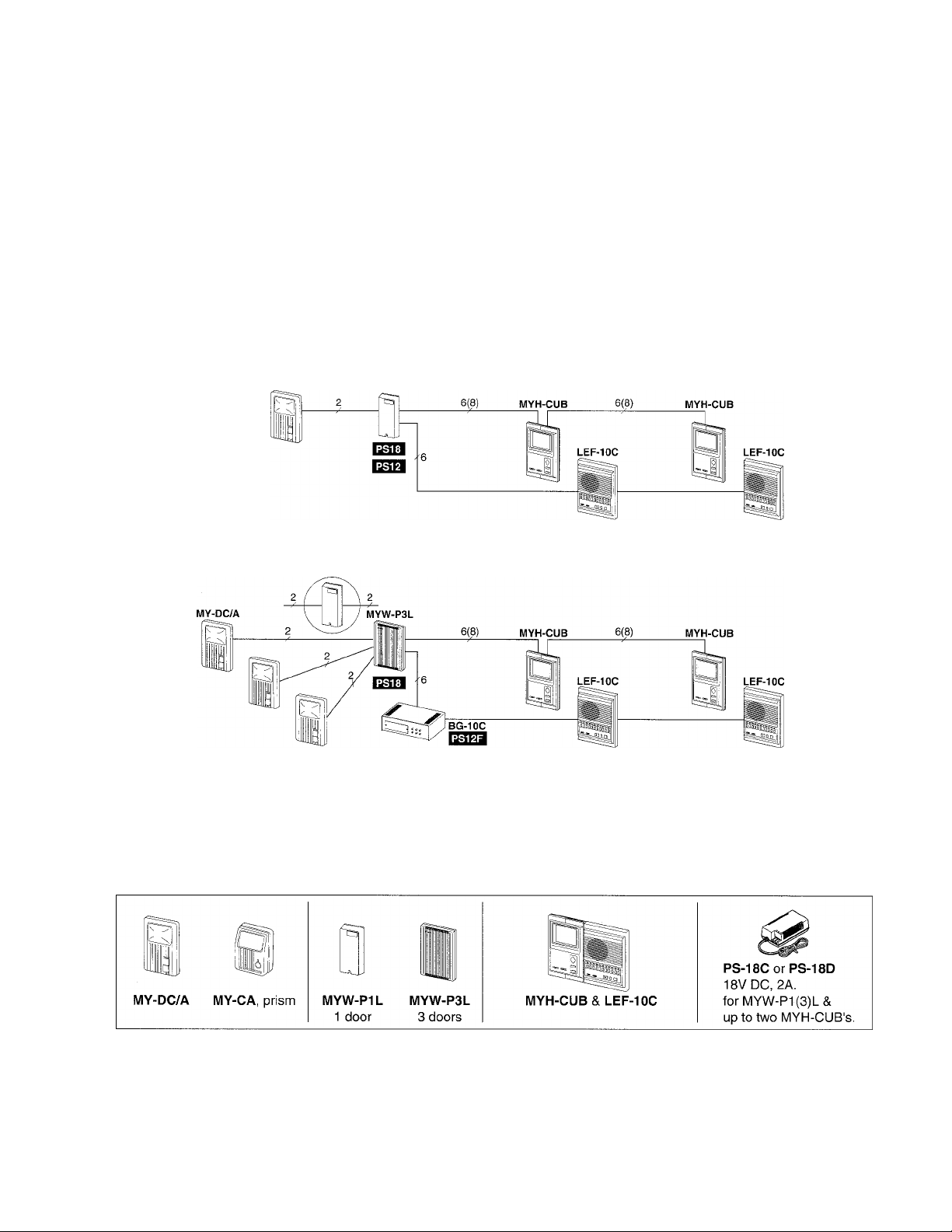
MYH-CUB is a semi-flush PanTilt video monitor for use with LEF-5C and LEF-10C Master Sentry system. MYHCUB monitor, in conjunction with MYW-P1L or P3L, provides video for 1 to 3 entries for door answering and
surveillance.
MY-DC/A MYW-P1L
Via MYW-BA
★ Refer to Installation & Operation Manuals packed with
MYW-BA & BG-10C
Components available
PanTilt door stations • PanTiit door adaptor • MASTER SENTRY & Monitor • Power suppiy
Other models available:
• PanTilt door stations: MY-DG/A. Prism MY-EA, MY-FA. Wide-angle MY-DS. Overhead MY-CA (in MYW-CA).
• All Call, music & chime: either BG-10C or BGR-10A with AM/FM tuner. BG-10C requires PS-12F power supply,
12V DC, 2.5A. BGR-10A requires PS-24C.
• MYW-BA Long-distance adaptor can be added for an entry that is farther than 100m (330’) and up to 300m (980’).
for complete diagrams.
Package Contents
PanTilt video monitor (MYH-CUB)
Packet of screws
Installation & Operation Manual
MYW-P3L,
-1 -
Page 2
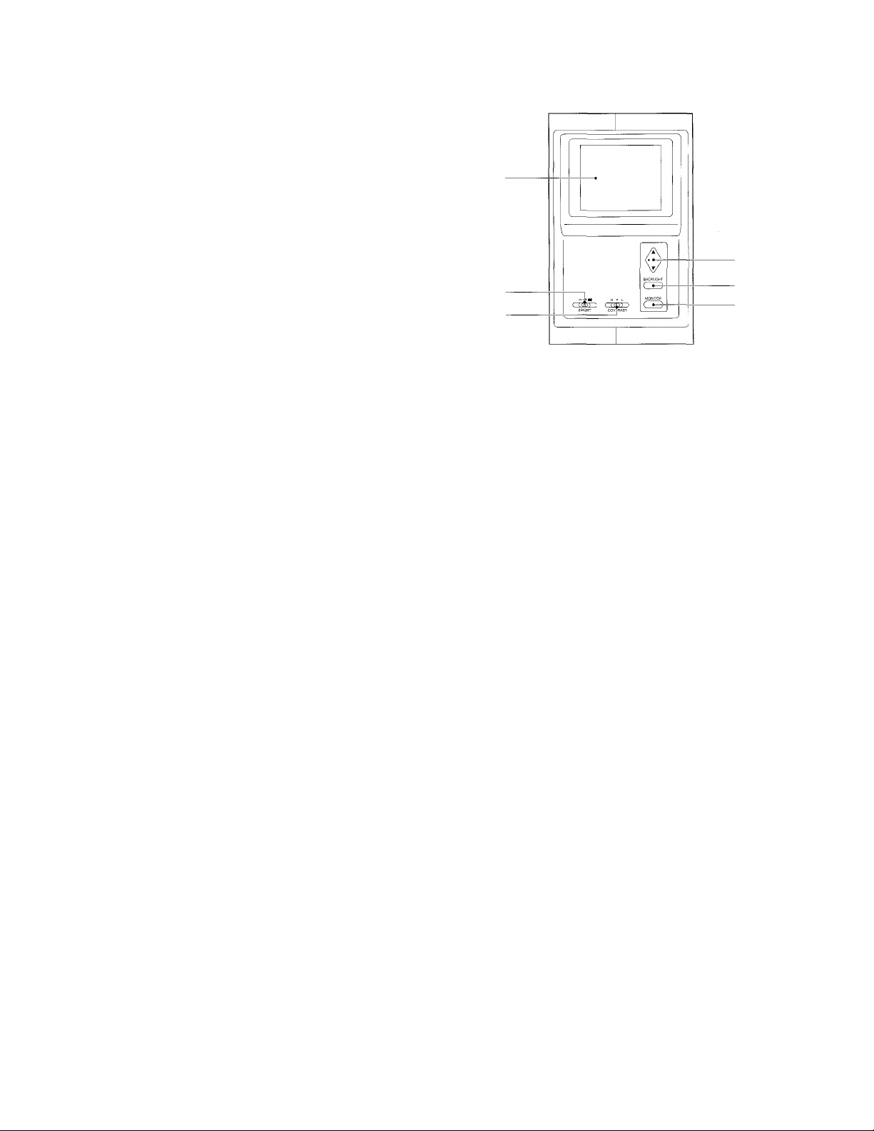
NAMES AND FEATURES
1- Video monitor
2- Brightness control
3- Contrast control
4- PanTilt control pad
5- Backlight button
6- Monitor button
FEATURES
• Semi-flush mount.
• Used with LEF-5C or LEF-10C master stations.
• Two MYFI-CUB monitors, expandable w/add’l PS-18C or PS-18D.
• All monitors turn on or off at the same time.
• Presetting prism camera angle (MY-CA or MY-FA).
J PRECAUTIONS ON INSTALLATION & WIRING---------------------------------------------------------
Acaution
★ Do not connect any terminal on any unit to AC power lines to prevent fire or unit damage.
★ High voltage is present on the monitor unit inside. Do not open MYH-CUB without first unplugging the power
supply, to prevent electric shock.
★ Do not attempt to install or connect wires on MYH-CUB equipment while system’s power supply is plugged in.
★ MYH-CUB and related equipment, except door station, are designed for indoor use only. Do not install outdoors.
★ Do not connect any other power source than specified on terminals -r, -. Doing so can damage the MYH-CUB
equipment.
★ For system’s installation, there is no need to disassemble the equipment, except to open the unit for wiring. Do
not access the PC board or any components unless properly qualified.
★ Any other manufacturer’s products installed with this system (door release, external signalling device, etc.) are
not covered under Aiphone’s warranty.
★ Do not mount MYH-CUB equipment in the following places, as it may cause the system to malfunction:
• High or extreme cold temperature areas: under direct sunlight, near equipment that varies in temperature,
near air-conditioner, inside a refrigerated area, etc.
• Places subject to moisture or humidity extremes.
• Places subject to environmental conditions, such as dust, oil, chemicals, etc.
★ MYH-CUB is an electrical device, which must not be subejcted to water, or any other liquid.
★ Weather conditions, such as lightning strorms, may cause damage to MYH-CUB equipment. We recommend that
power surge protection be installed as follows: (However, this does not guarantee that no damage will occur).
If the power supply has a GROUND terminal, take it to an earth ground. In this case, a separate surge arrester
is not necessary.
When using a power supply that has no GROUND terminal,
install a surge arrester near the output as shown.
DC power
supply
Install a surge-arrester (discharging voltage:
100-180V) at a point close to the output,
taken to earth ground.
INTERCOM
or ADAPTOR
DC 18V
Surge-arrester
— Grounded
Before actually installing MYH-CUB system, the contents on pages 3-5 must be thoroughly read and understood.
2-
Page 3

I WIRING
------------------
Actual terminal locations
Impedance-matching switch
(shipped in ON position):
Change to OFF pos. except
on the last MYH-CUB.
A1, A2 : For video & audio signals
B1, B2 : For video output
U1 : For output control
U2 : For input control
MYH-CUB chassis
Inside view
; 18V DC power supply.
Cable requirements
Use 6 conductor cable, non-twisted of 0.65mm or 1 .Ommo, 22AWG or 18AWG (8 conductors to increase
distance to farthest MYFI-CUB. Double wires on +!- terminals.).
★ Terminate unused wires with a 120Q resistor at both ends.
★ MYH-CUB video cable must be in a separate jacketed cable from LEF-C audio cable.
Presetting camera angle on MYH-CUB
For PanTilt prism camera only: MY-CA, MY-EA, MY-FA only.
1. Turn video monitor off. 10 seconds or more must elapse.
2. Press both MONITOR and BACKLIGHT simultaneously.
3. Release only MONITOR, but keep holding down BACKLIGHT for another 5 seconds.
4. Bottom quarter of MYH-CUB monitor will flash.
5. Move the door camera with PanTilt pad to desired viewing anige and position.
(while the screen is flashing).
6. When positioned correctly, press MONITOR to program the angle.
★ Backlight cancels the preset memory (while the screen is flashing).
★ To program for Prism camera 2, first have image of door 1 displayed.
Then, proceed through steps 1 to 6.
★ Reprogram when power failure.
WIRING DIAGRAM
MYH-CUB monitors (1 to max. 4) can be expanded with an additional PS-18C or 18D power supply.
MYW-P1L
To MY-DC/A
★ Do not connect + wire between
Monitors 2 and 3, powered by
different power supplies.
> LEF network
K10-
: PS-18C or PS-18D
★ MYW-P3L terminal configurations are different from MYW-P1L.
Internal VIDEO wires are exactly the same.
-3-
Page 4

MOUNTING
MYH-CUB & LEF-5C/10C
■ BGR-10A, MYH-CUB & LEF-5C/10C
★ Chassis is 40mm, 1-9/16" deep.
■ Mounting height
Mount the video monitor so that the center of monitor screen comes to the eye level
of the user.
■ Semi-flush mounting
1. Cut proper size holes on the wall as shown for mounting components, or use
appropriate back boxes.
2. Separate the chassis from each LEF & MYH-CUB.
3. Put LEF & MYH-CUB chassis together with a joint bracket.
4. Mount 2 or 3 chassis assembled with 4 supplied screws.
5. Make wire connections on each chassis according to the wiring diagrams.
6. Reconnect LEF & MYH-CUB, plugging in to each chassis.
7. Mount the front cases to chassis.
8. When installation is complete, plug in power supplies, and test the listed features.
★ The 3-piece combination is wider than a stud space (16"). In order to mount without
the BBX-6E (USA), the center 2x4 has to be cut and framed where the intercom will
be placed.
-4-
Page 5

OPERATIONS on LEF-10C & MYH-CUB
Video
monitor
Tilt camera up and down
up
BRIGHT
CONTRAST
PanTilt door station call-in
1. Press CALL button on PanTilt door station.
2. A mono electronic tone or chime tone is heard on LEF master.
MYH-CUB monitor(s) turns on, staying on for 45 seconds.
3. Depress a lit Station-Select button to establish the channel.
4. Press TALK button to reply.
5. At conclusion, press OFF button to disactivate both audio and video.
★ Image is on for 2-1/2 minutes during communication.
Press MONITOR button to turn on again if needed.
Surveillance w/pan-tilt scanning
1. In standby, activate MYH-CUB monitor(s) with MONITOR button.
2. Press MONITOR button a second or third time to switch image to entry 2 and 3.
Each image is held for approx. 2-1/2 minutes.
3. Press MONITOR to turn off, or it will turn off in 2-1/2 minutes.
To monitor audio and video
1. Select the selector button for the door on the LEF. The monitor is activated,
and master station is in the listen mode.
2. Press OFF to turn off both audio and video. If left on, monitor will turn off in 2-1/2 minutes.
PanTllt pad
Backlight button
MONITOR button
to left ■
- Pan camera
to right
down
Backlight & Contrast controls
BACKLIGHT compensates for weak contrast image.
Put CONTRAST to left H position, to sharpen image
in a dimly lit entry.
Pan & tilting door camera
While the image is alive, pan and tilt the camera,
pressing each edge.
if Image viewing area;
MY-DC/A, MY-DG/A:
• 49cm Vert., 66cm Horiz. (20"V x 26"H)
• Max. scanned; 76"V 122"H
90cm Vx 180cm H(3'V, 6'H)
-180 (6’)
Prism MY-CA, MY-EA, MY-FA
• 51cm Vert., 72cm Horiz. (20"V, 29"H)
• Max. scanned: 76"V and 109'H
90cm V, 140cm H (3'V, 4'7"H)
( (0 0) )
BRIGHT
Darker« Brighter
High - Medium - Low
180 (6’)
51
(20")/
i /
72 (29") ►
110(3', 7")
H • L
( (GD) )
CONTRAST
Unit: cm (approx.)
90
(3')
140cm, 4'7"
when camera
is non-tiited.
Page 6

TECHNICAL PRECAUTIONS-------------------------------------------------------------------------------------------
Operation:
★ When operating PanTilt control pad, motor sound may be heard. When camera reaches the edge of each direction, release
the control pad. While one person is operating PanTilt or Backlight button, all other MYH-CUB’s can not operate.
Installation:
★ To avoid noise from power supply line, take G terminal of PS-18C or 18D power supply to earth ground.
★ Audio wiring; Keep audio wires at least 20”, 50cm away from AC power lines, fluorescent lights, and dimmer switches.
IMPORTANT:
★ In LEF video system, run two separate cables, with LEF audio wiring together and MYH-CUB wiring together in a completely
separate cable. Using the same cable for both audio and video terminals will cause severe interference to the LEF audio
communications.
SPECIFICATIONS
Power source:
Power supply;
Video monitor:
Scanning line:
Communication:
18V DC, 0.4A max. Standby: OA.
Supplid by PS-18C or PS-18D via MYW-P1L or MYW-P3L.
4” direct view flat CRT.
525 lines.
Call-in timer; 45 sec. Monitor timer: 2-1/2 min. during LEF-C communication, extendable with
MONITOR button. Station-Select button activates both audio and video of door camera.
Wiring:
6 or 8 wires, non-twisted, non-shielded between MYW-P1 (3)L and two MYH-CUB.
The same 6 or 8 wires, non-twisted, non-shielded between MYH-CUB’s.
★ Must be separately jacketed from audio cable.
Wiring distance:
I.Ommo 18AWG
MYW-P1/3L to MYH-CUB 1 75m 245’
MYW-P1/3L to MYH-CUB 1 - 2
With 8 wires (-1-, - doubled)
Dimensions:
Weight:
This equipment has been tested and found to comply with the limits for a Class B digital device, pursuant to Part 15 of the FCC Rules. These limits are designed
to provide reasonable protection against harmful interference in a residential installation. This equipment generates, uses, and can radiate radio frequency
energy and, if not installed and used in accordance with the instructions, may cause harmful interference to radio communications. However, there is no
guarantee that interference will not occur in a particular installation. If this equipment does cause harmful Inteference to radio or television reception, which can
be determined by turning the equipment off and on, the user is encouraged to try to correct the interference by one or more of the following measures:
• Reorient or relocate the receiving antenna. • Connect the equipment into an outlet on a circuit different from that to which the receiver is connected.
• Increase the separation between the equipment and receiver. • Consult the dealer or an experienced radio/TV technician for help.
-i-
-i-
Aiphone warrants its products to be free from defects of material and workmanship under normal use and service for a period of two
-t-
years after delivery to the ultimate user and will repair free of charge or replace at no charge, should it become defective upon which
-i-
-!♦
examination shall disclose to be defective and under warranty. Aiphone reserves unto itself the sole right to make the final decision
whether there is a defect in materials and/or workmanship; and whether or not the product is within the warranty.
-S-
-s-
This warranty shall not apply to any Aiphone product which has been subject to misuse, neglect, accident, or to use in violation of
-5-
instructions furnished, nor extended to units which have been repaired or altered outside of the factory. This warranty does not cover
-t-
batteries or damage caused by batteries used in connection with the product.
This warranty covers bench repairs only, and any repairs must be made at the shop or place designated in writing by Aiphone.
Aiphone will not be responsible for any costs incurred involving on site service calls.
«1* ♦
240 H X 150 W X 36 D (mm). 9-7/16” H x 5-5/16” W x 2-7/8” (total).
1.0kg. (2.20 lbs.) approx.
WARRANTY
35 m 115’
75m 245’
•i*
•i-
-i*
Aiphone Co., Ltd., Nagoya, Japan
Aiphone Corporation, Bellevue, WA, USA
MYH-CUB-I(E) 0596D
COMMUNICATION SYSTEMS
® AIPHONE
HOME, BUSINESS, INDUSTRY.
Printed in Japan (E)
 Loading...