

Page 1
83352900 0301
0 AlPHONE
VIDEO SENTRY PanTilt Plus
PANTILT VIDEO ENTRY SECURITY INTERCOM
Modsls: MY“2CDj Master station with monitor
M Y H “2 C D, Sub station with monitor
INSTALLATION & OPERATION MANUAL
This Manual and the Markings on the product contain
various symbois in order that the product can be used
safely and properly, and that the installer and user
are protected from injury and property damage.
The following precautions must be thoroughly read and
understood before proceeding.
PRECAUTIONS ON INSTALLATION & WIRING
A\ WARNING Negligence could result in death or serious injury.
/j\ CAUTION Negligence could result in injury or damage to property.
The following precautions aiso appiy to MYH-2CD sub station with monitor.
/?\ WARNING
CAUTION
A
1. Do not connect any power source other than specified to terminals
Fire or damage to the unit could result.
2. Do not open MY-2CD. High voltage is present inside, and it can cause electric shock.
3. Do not change or alter MY-2CD. It can cause fire or electric shock. ^
4. Make sure wires are connected properly before plugging in power supply.
5. Keep the MY-2CD unit away from water or any other liquid. Fire or electric
shock could result.
6. Do not put any forcible strength on the video monitor. Damage may result.
7. Keep AC plug away from moisture or dust. ^
8. Keep AC cord away from being marred or crushed.
9. Do not plug or unplug with wet hands. ^ ^
10. Do not put any metal into MY-2CD through openings. It can cause fire,
electric shock or unit damage.
1. Do not install or make any wire terminations while power supply is plugged in.
It can cause electrical shock or damage to the unit.
2. Do not manually hold down hook switch to verify chime volume. It sounds very
loud in the handset, and can cause hearing damage.
3. Mount MY-2CD on wall in a convenient location, but not where it could be
bumped or jarred.
4. In case of electrical storms, unplug power supply from AC outlet,
fire, electric shock, or power surge damage.
5. Do not install MY-2CD components in any of the following locations, as it may ^
cause the system to malfunction; 'ey
- High or extreme cold temperature area: under direct sunlight, near equipment
that varies in temperature, in front of air conditioner, inside a refrigerated area, etc.
- Places subject to moisture or humidity extremes.(bathroom, cellar, greenhouse, etc.]
- Places subject to environmental conditions, such as oil, dust, chemicals, salt, etc.
- Places subject to constant vibration or impact.
- Places where noise generating devices such as TV or radio are close by.
PACKAGE CONTENTS
Master station w/monitor MY-2CD
or Sub station w/monitor MYH-2CD
Packet of screws
Installation & Operation Manual
on MY-2CD.
0
0
JS)
0
o
o
It can cause
o
-
GENERAL PRECAUTIONS
A
1. MY-2CD equipment, except for door station MK-DBC, etc. is designed for indoor use only.
2. MY-2CD system is not operational during a power failure.
3. in areas where broadcasting station antennas are close by, intercom system
4. Keep all DC wiring at least 30cm(1') away from AC 100~240V wiring, fluorescent
Examples of Symbols;
GENERAL PRECAUTIONS: - A mark
A
indicates caution statement (incl. danger
and warning), which is specifically
shown inside.
Do not install outdoors.
may be affected by radio frequency interference.
lighting, or dimmer switches. Otherwise, cross AC wiring at a 90°angle.
GENERAL INSTRUCTIONS; - O mark
indicates contents which demands a
O
specific action shown inside or attached.
GENERAL PROHIBITIONS: - Q mark
indicates contents which prohibit a specific
0
action shown inside or attached.
DISMANTLE PROHIBITIONS
MOISTURE PROHIBITIONS
1 -
Page 2
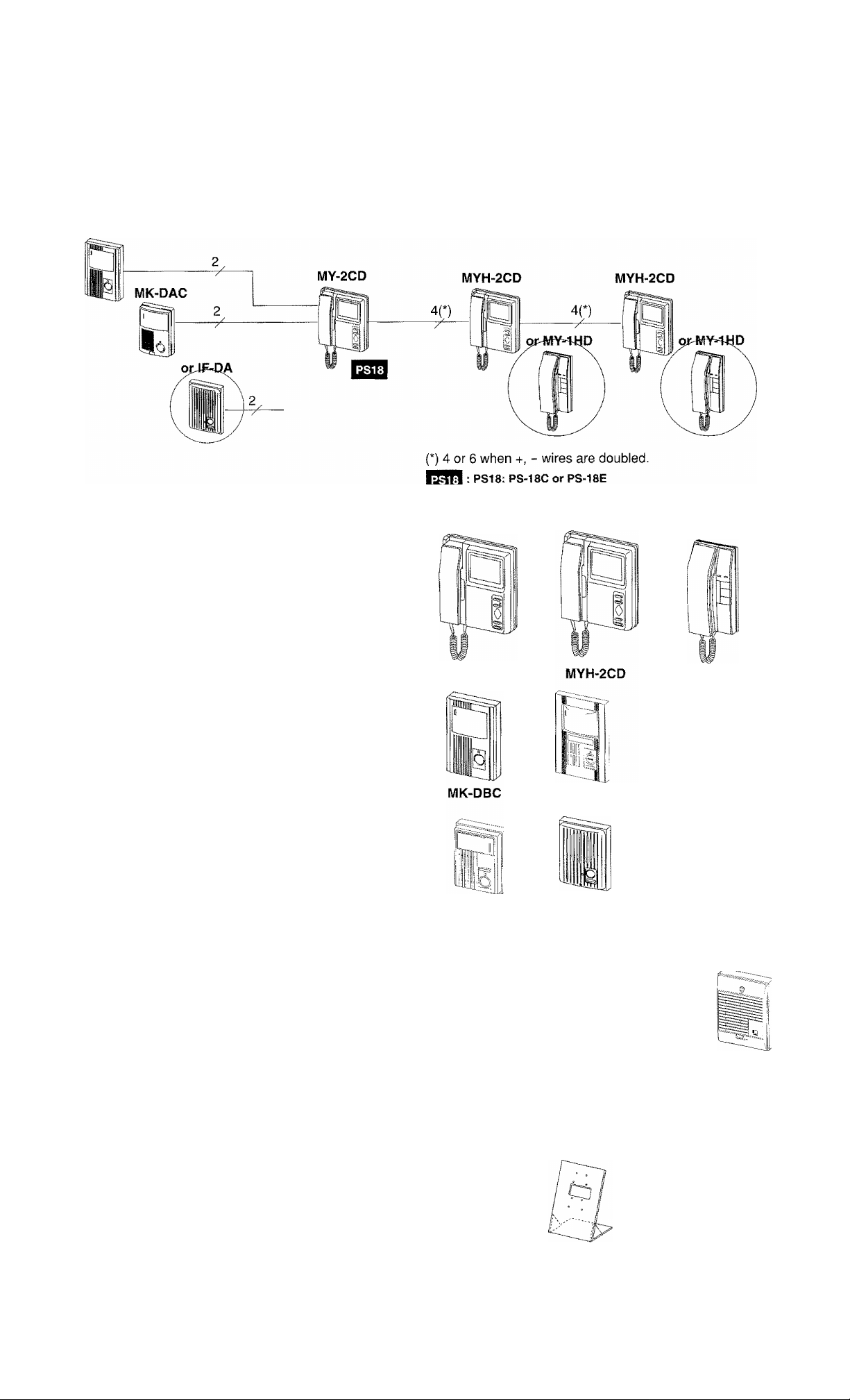
1 SYSTEM OUTLINE & COMPONENTS
MY-2CD is a master station for PanTilt Video Entry Security Intercom, which can incorporate max. 2 PanTilt video door
stations and up to 3 monitor stations. Audio only door station and audio-only handset sub station are optional.
SYSTEM LAYOUT
MK-DBC
COMPONENTS AVAILABLE
MY-2CD, Master station w/monitor
MYH-2CD, Sub station w/monitor
MY-1HD, Audio-only sub station
MK-DBC, PanTilt video door station, semi-flush
MK-DGC, PanTilt, w/aiuminum cover
MK-DAC, PanTilt, surface mount
MY-DS, Wide-angle fixed camera door station
IF-DA, Audio door station (any lE/lF series)
other models
IViY-DC/A, IViY-DG/A, fi/IY-EA, MY-FA, ftilY-CA
MY-2CD
MY-DS
MK-DGC
IF-DA
MY-1HD
MK-DAC
OPTIONS
MYW-BA, Long distance adaptor
RY-3DL, Door release adaptor
KC-32EU, Picture memory unit
IER-2, Call extension speaker
Mounting accessories
MKW-R, Surface mount box for MK-DBC, MK-DGC.
KAW-D, 30' Angie Box for surface mount video
door stations MK-DAG, MY-DS.
MCW-S, Desk stand for MY-2GD, MYH-2CD.
MYW-BA
KAW-D
RY-3DL KC-32EU
MCW-S
MKW-R
IER-2
Page 3
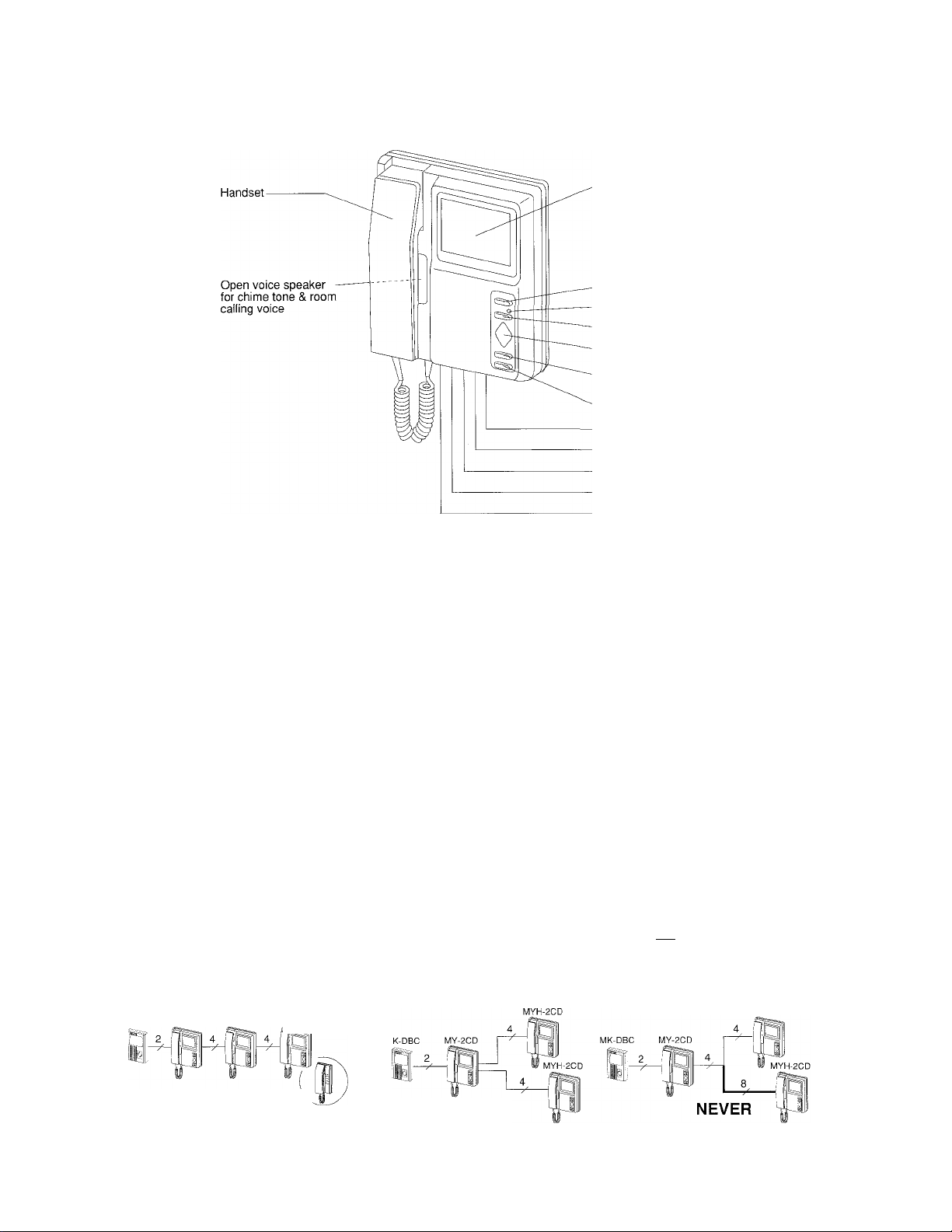
2 NAMES & FEATURES
MY-2CD, MYH-2CD
Video monitor (4" CRT)
Door release button
Door call-in LED
ROOM call button
PanTilt control pad
BACKLIGHT control button
MONITOR button
Chime/pre-tone volume control (TONE)
Brightness control (BRIGHT)
Contrast control (CONTRAST)
A-B switch (SW1)
RESET switch
FEATURES
• Multiple PanTilt door & monitor system with a variety of configurations.
• Max. 3 inside monitor stations. Audio-only sub station(s) in place of sub station(s) w/monitor.
• Max. 2 PanTilt door stations.
• Optional audio door station.
• Monitor audio & video handsfree.
• All call type internal calling and communication.
• Door release button. Selective door release control with RY-3DL adaptor.
3 INSTALLATION
--------------------------------------------------------
/i\ Precautions on wiring
1. Use parallel conductor cable to connect video door station. Do not use any other
cable like coax cable, individual wires, shielded wire, or twisted pair.
2. When existing chime wires are used, be sure to locate and disconnect the AC
transformer.
3. If unused wires exist in the cable, terminate each extra pair with a 120 Ohm
resistor at each end of wires (on audio sub station end as well). Extra wires can
interfere with video signal.
4. Keep audio/video wires more than 30cm(1') away from AC100~240V power lines.
It will cause noise in communication and possible malfunction.
5. Run internal wiring of audio/video system in such a manner that the cable is run
from master to sub without any splices, which will create inferior video quality.
YES
Wire monitor to monitor
(daisy-chain)
MK-DBC MY-2CD MYH-2CD MYH-2CD
NEVER
Homerun to master
YES
PARALLEL WIRE
120 Ohm
A2
(B2)|
MK-DBC
(or MY-2CD)
NEVER include incoming & outgoing wires
in the same jacketed cable.
NEVER
COAXIAL CABLE
------^UNUSED WIRES
: 120 Ohm
Q-
_y—QaT]
r—SMI
MY-2CD
(or MYH-2CD)
MYH-2CD
MY-1HD
Note: The above wiring method also applies to MY-1 HD audio sub station.
Page 4

3 INSTALLATION (continued)
Mounting locations & height
Do not install master & sub stations with
monitor in a place strongly sunlit.
System selector "SW1' setting
MY-2CD, MYH-2CD BOTTOM VIEW
RESET SW1 CONTRAST BRIGHT TONE
1 A B ^
"RESET" switch setting
M*L
n 11™ I n
(3-level) (3-level) (3-tevel)
Mount the station so that the video monitor
comes at the user’s eye level.
On MY-2CD master station, do not change A setting. Only on 2nd (middle)
sub station of 3-station system, either MYH-2CD or MY-1HD, set to B position
(for impedance-matching).
Note: When MY-2CD is used for Aiphone VY-EM Condo. System, change
setting to B position on MY-2CD.
After completing all the wiring and turning on the power supply, operate as
follows;
The system will automatically initialize when powered on.
To re-initialize when powered on, press RESET switch on one room station (any).
The call-in LED lights, then goes off in 15 to 30 seconds (approx.) and the system
becomes operable. The RESET switch operation becomes necessary when power
supply is turned off and on (after power failure, etc.).
Call extension
Power supply
4 WIRING DIAGRAMS
1. Two PanTilt video door stations
MK-DBC IER-2
One IER-2 call extension speaker can be added to sound a chime tone in a
remote location. Connect wires from S-r, - terminals on MY-2CD.
Use specified power supply to ensure proper system operation.
If communication has noise interference, connect GND of power supply to ground.
----------
AC trans.
-4-
Page 5

2. One each PanTMt video & audio door station
MK-DBC
A1
A2
EL-9S
(any door)
IF-DA
AC trans.
+
______
IER>2
P
L
m
MYH-2CD
SW1
□0
TaTI [bTI
1A2| 1^
IER-2
■ P'
P
\ /
MY-1HD
MY-1HD
SW1
EC
"ÀT1 [bT
A2I [B2
— n
rnnn : PS-18C or PS-18E
Take G terminal to earth ground.
MY-2CD
SW1
DJ
1A1
ìbT
1A2!
B2
2A:
2A2
U1
El
\
L+
L-
/
[G
3. Long-distance application with WiYW-BA
IER-2
Page 6

4 WIRING DIAGRAMS (continued)
MY-2CD with 2 door releases
MK-DBC
EL-9S
MK-DBC
3
0
MY-2CD
/j\ Cut off and insulate all the unused wires.
KC-32EU Picture Memory Unit
MK-DBC KC-32EU
MYH-2CD
RY-3DL
Terminal "b3" remains unused.
Powered by PS-18C(E) of system.
3-wire connector is required to plug
into CN6, located inside the unit.
MYH-2CD
For actual wiring, refer to the Instructions packed
with the RY-3DL.
MK-DBC
EL-9S
MK-DBC
EL-9S
EL-9S
MY-2CD
/t\ Cut off and insulate all the unused wires.
MYH-2CD
ta : AC Transformer
nm PS-18C, PS-18E
RY-3DL
Terminals "b2 & b3" remains unused.
Powered by PS-18C(E) of system.
3-wire connector is required to plug
into CN6, located inside the unit.
MYH-2CD
PT-1210N in USA
Picture memory unit:
KC-32EU holds one video door station only.
Powered by a DC 18V power supply (separate or common).
PS-18CorPS-18E
iacfM-2: PS-18YC/A, PS-18YE or PS-18ME
5 MOUNTING
MY-2CD & MYH-2CD master & sub stations can either be wall-mounted or placed on a desk stand (Model: MCW-S).
MY-2CD
MYH-2CD
Waii-mounting
Loosen screw on bottom of front case, and separate
the front case from chassis by sliding the front case
upward and pulling away. Disconnect the front case
from the chassis, unplugging two connectors. Do not
force the unit apart.
2. Install the chassis to single-gang box or to wall
surface.
3. Terminate all the wires on screw terminals inside the
chassis.
4. When wiring is completed, reconnect the front case
to the chassis. Aligning from the top, slide the front
case downward on chassis into place. Tighten screw
at bottom of the front case.
Desk-top mounting on MCW-S
MY-2CD Chassis Used for
MYH-2CD
Screw (w/terminal
section)
MCW-S
Stand
mounting
MY-2CD,
MYH-2CD
/
Nut{4)
Page 7

6 OPERATIONS
Pan-and-TMt door camera
When a door call Is received or when monitoring a door, press the edge of control pad to
move the door camera up, down, or side to side.
Backlight control button adjusts for extreme light.
Answer door
A visitor presses momentarily CALL button on a door station. At all inside stations, 4- or
2-tone chime sounds and monitor turns on with image (8-tone chime from audio door
station). On any inside station, pick up hadnset to reply. The rest inside stations turn off.
If not replied, video monitors turn off in approx. 45 sec. automatically.
To activate door release; After identifying a caller, press and hold door release button.
Monitor door audio & video handsfree
In standby, press MONITOR button to view and hear the door station.
Press once for door one, press twice for door two (if included). Monitor will stay on for
approx. 2 1/2 min.
Press MONITOR button to turn monitor off.
Internal communication
Pick up handset on any inside station and press ROOM call button. After pre-tone sounds
at other stations, make announcement into handset.
MY-1 HD sub station also receives pre-tone and voice.
When door calls in during communication;
Chime tone is heard at communicating stations and monitor turns on with image. Hang up
handset at both stations to end present call.
Pick up handset again to answer the door.
Connect audio door station
To monitor the audio of an lE/IF door station, pick up handset and press MONITOR button
twice. (Separately from the above operation "Monitor audio & video")
RESET switch
A-B setting switch (SW1)
MY-2CD, MYH-2CD BOTTOM VIEW
RESET SW1
I A B
CONTRAST
H • L
BRIGHT TONE
¡M I n I mm-j-
Li
(3-level) (3-level)
I)
- 7
Chime/pre-tone volume control (TONE)
Adjust volumes of chime and room call-in
voice to 3 positions.
Brightness control (BRIGHT)
Adjusts screen brightness to 3 positions.
Contrast control (CONTRAST), adjusted to 3 positions.
* To view dim entry area, put contrast to
left H position and decrease brightness.
Page 8

7 TECHNICAL PRECAUTIONS
Before asking for repairs: In case the system does not provide satisfactory performance, check possible causes, such as;
Unplugged? Disconnected wire? Shorted wire?
If the system continues to malfunction, consult the dealer or distributor that you purchased the
product from.
Do not open any monitor station without first unplugging power supply. High voltage is present
inside the monitor.
When an inside station does not place a normal call, press RESET switch on that station.
This RESET switch operation is necessary if power supply is unplugged and plugged in again.
When the outside temperature lowers rapidly (after rain, etc.), the camera lens may be fogged
and display a dim image on the video monitors. This is not a malfunction, and will return to
normal shortly.
Cleaning:
Clean your MY-2CD equipment with a soft cloth dampened with neutral household cleanser.
Video door station is designed to be weather resistant. Do not spray high-pressure water
directly onto door station.
8 SPECIFICATIONS
Power source: DC 18V.
Power supply: PS-18C (AC 120V) or PS-18E (AC220
Consumption:
MY-2CD & 2 video doors
MY-2CD & one MYH-2CD
MY-2CD&two MYH-2CD
Video monitor:
Scanning line:
Wiring distance:
4 inch direct view flat CRT.
525 lines.
1VIY-2CD to PanTilt door station;
MY-2CD to MY-DS fixed wide-angle;
MY-2CD to lE/IF door (audio);
Between inside monitor stations;
Max.
1.0A
1.48A
1.96A
2-monitor system;
Diameter 1 .Omm0
Distance
! AWG
I
Distance
18AWG
Standby
0.14A
0.21A
0.28A
56m
185'
240V).
Diameter
Distance
AWG
Distance 165'
Diameter
Distance
AWG
Distance 330'
Diameter
Distance
AWG
Distance 450’
{*)1.Omm0
75m
(*)18AWG
245’
Call-in:
Communication;
Dimensions:
Weight:
O.65mm0 1 .Omm0
50m
22AWG
O.65mm0 1 .Ommo
100m
22AWG 18AWG
O.65mm0
150m
22AWG
3-monitor system;
Diameter
Distance
AWG
Distance
(*) Total of 6 wires, with +, - wires doubled.
1 .Omme
18AWG
Door call-in with 4- or 2-tone
chime and image approx. 45 sec.
(8-tone from audio door).
Pre-tone and voice from other
inside station.
Simultaneous with handset.
(MY-2CD & MYH-2CD)
230 Hx195Wx69D(mm).
9" Hx 7-1/2" Wx 2-3/4" D.
Approx. 1,500g (3.31 lbs.).
100m
18AWG
330'
200m
650'
1 .Omm0
360m
18AWG
1,000'
(*)1.Omm0
28m 56m
(*)18AWG
90’ 185'
This equipment has been tested, and found to comply with the limits for a Class B digital device, pursuant to Part 15 of the FCC Rules.
These limits are designed to provide reasonable protection against harmful interference in a residential installation. This equipment
generates, uses, and can radiate radio frequency energy, and if not installed and used in accordance with the instructions, may cause harmful
interference to radio communications. However, there is no guarantee that interference will not occur in a particular installation.
If this equipment does cause harmful interference to radio or television reception, which can be determined by turning the equipment off and
on, the user is encouraged to try to correct the interference by one or more of the following measures:
•Reorient or relocate the receiving antenna. • Connect the equipment into an outlet on a circuit different from that to which the receiver is
connected. »Increase the separation between the equipment and receiver. • Consult the dealer or an experienced radio/TV technician for help.
WARRANTY t
Aiphone warrants its products to be free from defects of material and workmanship under normal use and service for a period ^
of two years after delivery to the ultimate user and will repair free of charge or replace at no charge, should it become defective ^
upon which examination shall disclose to be defective and under warranty. Aiphone reserves unto itself the sole right to make 4the final decision whether there is a defect in materials and/or workmanship; and whether or not the product is within the ^
warranty. ^
This warranty shall not apply to any Aiphone product which has been subject to misuse, neglect, accident, or to use in violation
of instructions furnished, nor extended to units which have been repaired or altered outside of the factory. ^
This warranty does not cover batteries or damage caused by batteries used in connection with the unit. ^
This warranty covers bench repairs only, and any repairs must be made at the shop or place designated in writing by Aiphone. -iAiphone will not be responsible for any costs incurred involving on site service calls. ^
AIPHONE CO., LTD., NAGOYA, JAPAN
AIPHONE CORPORATION, BELLEVUE, WA, USA
AIPHONE EUROPE N.V., ANTWERP, BELGIUM
MY-2CD-I(E) 0301G
-8
COMMUNICATION SYSTEMS
AIPHONE
HOME, BUSINESS, INDUSTRY.
Printed in Japan (E)
 Loading...