

Page 1
83634400 0595® & AlPHONE
PanTilt MY Series ^
VIDEO-MONITOR, single entry
INSTALLATION & OPERATION MANUAL
CONTENTS
1 SYSTEM OUTLINE & COMPONENTS..................................................................................................1
2 NAMES & FEATURES...........................................................................................................................2
3 PRECAUTIONS ON INSTALLATION & WIRING...................................................................................3
4 WIRING..............................................................................................................................................4~9
5 MOUNTING..........................................................................................................................................10
6 OPERATIONS on MY-CU & MYH-CU.................................................................................................11
7 BEFORE ASKING FOR REPAIR.........................................................................................................12
8 SPECIFICATIONS................................................................................................................................12
SYSTEM OUTLINE & COMPONENTS ----------------------------------------------
MY-CU is a video monitor unit to enable an intercom to verify callers at a single PanTilt entry.
MYH-CU is a sub-monitor, to increase monitor location.
PanTilt door
station
MY-CU
Components available
MY-CU MYH-CU
Identically designed with Pan/tilt control pad.
MYH-CU 1
★ Prerun 8-conductor cable to extend
distance to MYH-CU 2. (See page 12)
MYH-CU 2
Package contents
Video-monitor (MY-CU or MYH-CU)
Mounting template
Packet of screws
Installation & Operation Manual
1 -
Page 2
Intercom combinable
• Chime tone intercoms
• PanTilt door station
WIY-DC WIY-FA MY-CA
Expanded system
IV1YW-P3CB
MYW-CA
MYW-BA
★ Also, refer to the Manuals of using intercom and
adaptor.
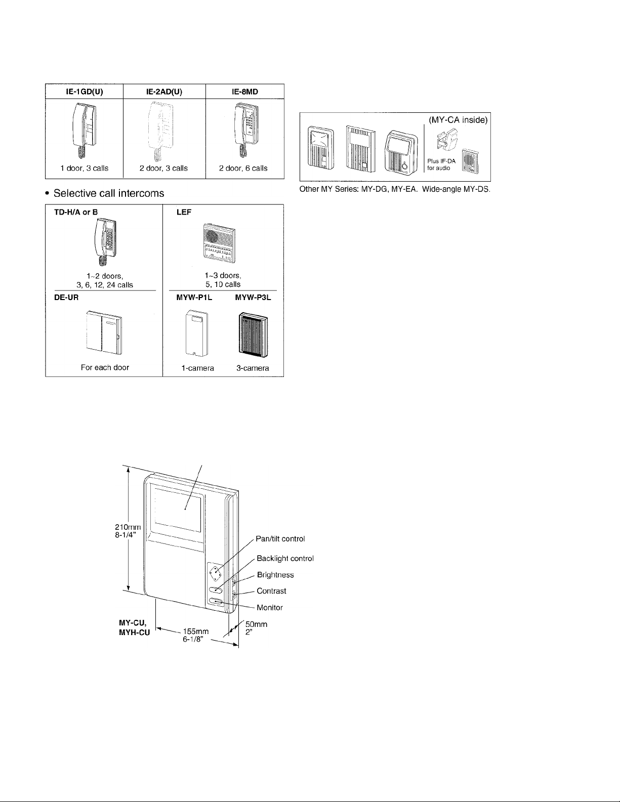
NAMES AND FEATURES
Video monitor
(4”CRT)
3-camera adaptor
Works with
IE-8MDand TD-H/A
or B
Long-distance adaptor
"C3
More than 100 m,
330’ application with
PE insulation cabie
Unitized design enables wall-mounting
attachedly to either side of intercom, or
separately.
Features
One PanTilt door system
One to 3 room monitors, expandable
Any monitor equipped with Pan/tilt, Backlight and Monitor buttons
Monitor button sees image handsfree, or extends viewing
Separate brightness & contrast adjusting
-2-
Page 3
I PRECAUTIONS ON INSTALLATION & WIRING -------------------------------------
/K CAUTION
if Do not connect any terminal on any unit to AC power lines to prevent fire or unit damage.
if High voltage is present on the monitor unit inside.
Do not open MY-CU/MYH-CU without first unplugging the power supply, to prevent electric
shock.
★ Do not attempt to install or connect wires on MY-CU equipment while system’s power supply is
plugged in.
----------
★ MY-CU and related equipment, except door station, are designed for indoor use only. Do not install
outdoors.
★ Do not connect any other power source than specified on terminals +, - . Doing so can damage the
MY-CU equipment.
★ For system’s installation, there is no need to disassemble the equipment. Do not open any MY-CU
system components unless properly qualified.
★ Any other manufacturer’s products installed with this system (door release, external signalling device,
etc.) are not covered under Aiphone’s warranty.
★ Do not mount MY-CU equipment in the following places, as it may cause the system to malfunction:
• High or extreme cold temperature areas: under direct sunlight, near equipment that varies in
temperature, in front of air-conditioner, inside a refrigerated area, etc.
• Places subject to moisture or humidity extremes.
• Places subject to environmental conditions, such as dust, oil, chemicals, etc.
★ MY-CU is an electrical device, which must not be subjected to water, or any other liquid.
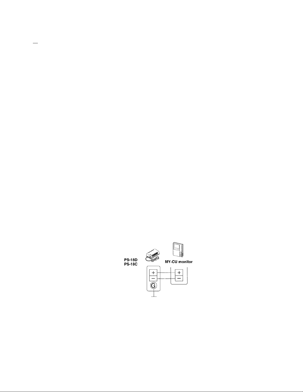
★ Weather conditions, such as lightning storms, may cause damage to MY-CU equipment. We
recommend that power surge protection be installed as follows: (However, this does not guarantee
that no damage will occur).
MY-CU
If the power supply has a
GROUND terminal, take it to an
earth ground. In this case, a
separate surge arrester is not
necessary.
Before actually installing the MY-CU system, the contents on pages 4 ~ 10 must be thoroughly read and understood.
-3-
Page 4
WIRING
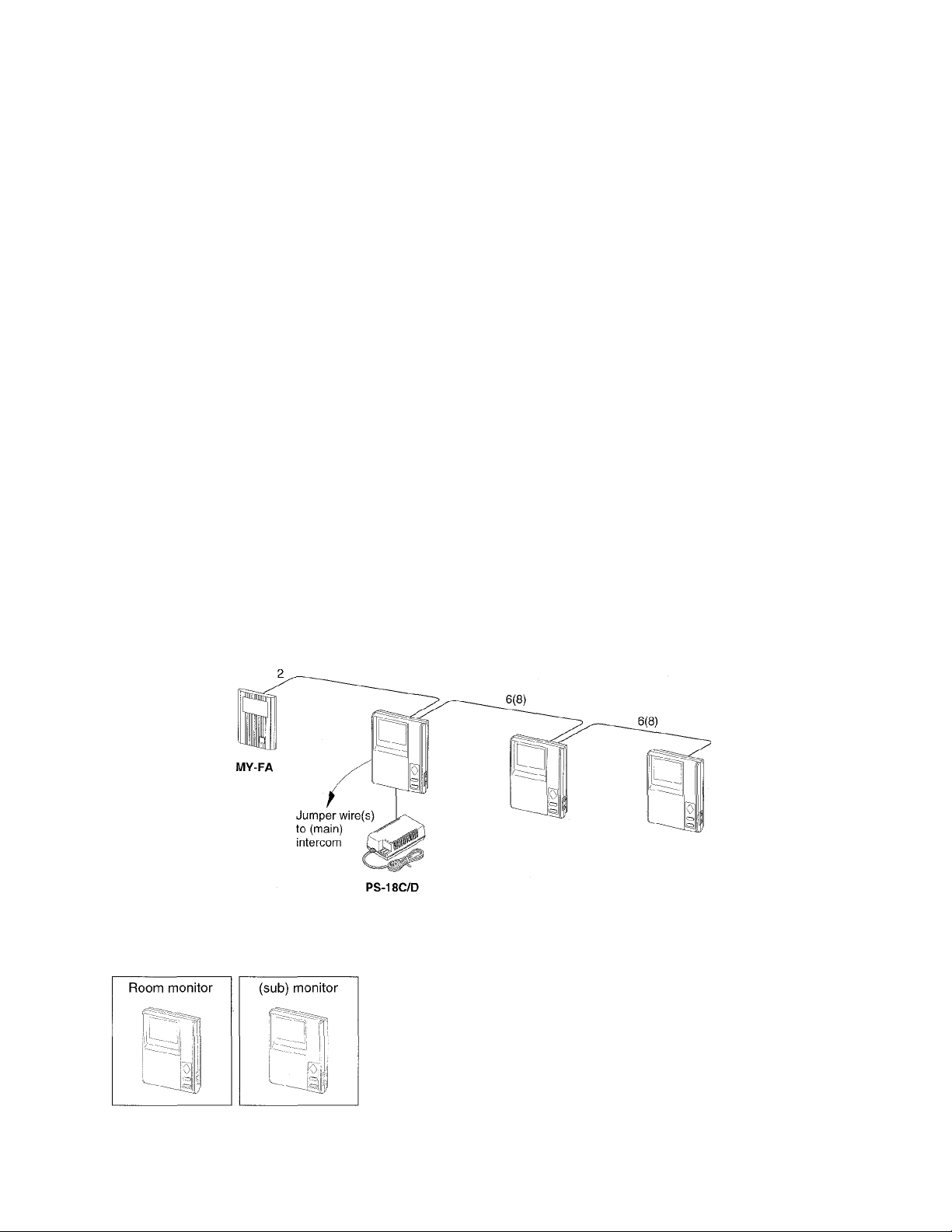
Single-entry, multiple-monitor system
MY-CU is capable of connecting one PanTilt door station and two additional
MYH-CU sub monitors.
It can be further expanded with an additional MYH-CU('s), by locating a power
supply(ies) for every 4 MYH-CU('s) (total 10 monitors).
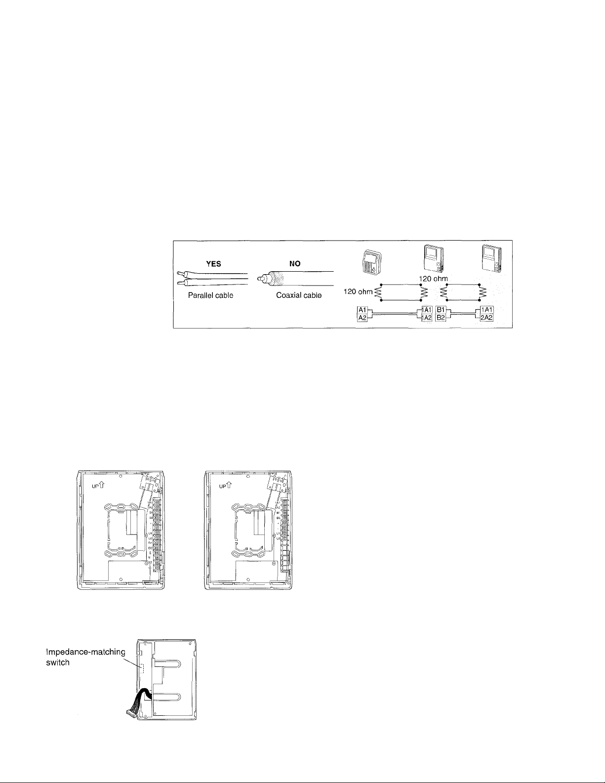
Cable requirements
PanTilt door station
Use a single pair (parallel) cable. Coaxial cable or 2 separate wires can not be
used. When existing doorbell or chime wires must be used, locate and
disconnect the bell transformer from the wires. Extra pair(s) in the installed
cable to video door station can affect the image quality, and must be terminated
with a 120 ohm resistor at each end of wires on both video door station and
video monitor(s).
Room monitors
Use 6-conductor (parallel) cable, 0.65 ~ 1.0 mm dia., 22 ~ 18AWG. The video
cable must be separately sheathed from intercom’s (any), running from monitor
to monitor without any reconnections on other junction. Max. 75 m, 250’ is
allowed from MY-CU to farthest MYH-CU in any configuration with 1.0 mm dia.,
18AWG. When locating a third monitor (MYH-CU) up to 75 m, 250’ away, 8conductor cable must be run monitor to monitor, as each -h, - wire has to be
doubled.
★ For proper operations, MYH-CU must be be fed 15.5V ~ 19.1 V.
Terminal block layout
Meaning of terminal symbols
1A1, 1A2
B1, B2
+, U1
U2
D1
D2
E
G
MY-CU MYH-CU
Impedance-matching
For video & audio signals
For video output
For power supply
For output control
For input control
For audio signai & image on
For detecting calling at
IF-DA & image off
For common line
Grounding
When MY-CU has an MYH-CU sub-monitor(s),
locate a switch to lower OFF on all MYH-CU(s),
while the initial ON may remain unchanged on
the last MYH-CU to terminate.
-4-
Page 5

Power supply
Use a PS-18D (PS-18C in North America) power supply(ies) to power entire MY-CU system. Do not
intermixedly use other manufacturer’s.
IE-8MD
or other
★ MY-CU must be
used with (main)
intercom in any
system.
WIRING DIAGRAM
2
MYH-CU
¡y
OFF |[OFF]
^1
N
V
PS-18C or
PS-18D
3
MYH-CU
5“
J t
MYH-CU
V f
★ Do not connect
+ terminai between
monitors 3 and 4
(nor between 7and 8)
4
Q
[o^
j/'
------
★ impedance-matching: Set the switch to OFF on all MYH-CU's
except on the farthest.
★ Locate a 2nd PS-18C (PS-180) at mid point MYH-CU 4-7.
MYH-CU
'
5
jOFFi
6
MYH-CU
1
¡5
i
OFF
7
MYH-CU
a
PS-18Cor
PS-18D
MY-CU to PanTilt door
Diameter 0.65mm 0.8mm
Distance
AWG 22AWG 20AWG
Distance 165’ 230’
50 m
70m 100m
1.0mm
18AWG
330’
• Two farthest stations (any pair)
Diameter
Distance 75m 120m
AWG
Distance
0,65mm 0.8mm
22AWG 20AWG 18AWG
250’ 380’ 630’
1.0mm
190m
Page 6

PanTilt IE-8MD with 2 video-monitors
STATION #
1
IE-8MD &
Single PS-18C or PS-18D powers both lE8MD and MY-CU, locating an MYH-CU on
75m, 245’.
One to 5 IE-8HD with 4-wire cable, station-tostation. PanTilt MY-CU monitor with 6-wire cable
separately sheathed. PanTilt door requires 2
parallel wires, connected directly to MY-CU
monitor.
■k Connecting jumpers
In single PS-18C(D) sourced system, a
D1 - D1 jumper is only required. Add another
D2 - D2 when IF-DA is installed.
Install a third jumper on E - E1, when a
separate audio & video power source is used.
4
IE-3HD &
I Wiring distance
MY-CU to PanTilt door
Diameter
Distance 50m
AWG
Distance 165’
MY-CU to farhest MYH-CU (2 monitors)
Diameter
Distance
AWG
Distance 115’
MY-CU/1E-8MD to power supply PS-18D(C)
Diameter 1.0mm AWG
Distance
0.65mm 0.8mm 1.0mm
70m 100m
22AWG
0.65mm 0.8mm 1.0mm
35 m 50m
22AWG 20AWG 18AWG
5m Distance
20AWQ 18AWG
230' 330’
160’ 250’
18AWG
75m
16’
-6-
IE-8MD to audio door station
Diameter
Distance
AWG 22AWG 20AWG
Distance
Two farthest stations (any pair)
Diameter 0.65mm
Distance 75m
AWG 22AWG
Distance 250’
0.65mm 0.8mm 1,0mm
150m 230m 360m
500’ 750’ 1,180’
18AWG
0.8mm 1.0mm
120m 190m
20AWG 18AWG
380’ 630’
Page 7

PanTilt video integration to TD-H/A or B
The DE-UR adaptor connects MY-CU system
in the middle point of TD-H/A or B installation.
MYH-CU 1 MYH-CU 2
Wiring distance
From DE-UR to power supply
Diameter 0.65mm
Distance 10m
AWG 22AWG
Distance 30’
From MY-CU to power suppiy
Diameter
Distance 5m
AWG 18AWG
Distance 16’
From MY-CU to PanTiit door MY-DC
Diameter 0.65mm
Distance 50 m
AWG
Distance
1.0mm
22AWG 20AWG 18AWG
165’
0.8mm 1.0mm
15m 20m
20AWG 18AWG
50’ 45’
0.8mm
70m
230’
-7-
1.0mm
100m
330’
Between TD-H intercoms (any pair)
Diameter 0.65mm 0.8mm
Distance
AWG
Distance 2,000’ 3,000’
From MY-CU to MYH-CU #1 (2 monitors)
Diameter 0.65mm 0.8mm
Distance 35m 50 m
AWG 22AWG 20AWG
Distance 115' 160’
From MY-CU to MYH-CU #2 (3 monitors)
Diameter
Distance
AWG 22AWG 20AWG
Distance 55’ 80’
650m 1,000m
22AWG
0.65mm
17m
20AWG
0.8mm 1.0mm
25m 45m
1.0mm
1,500m
18AWG
4,900’
1.0mm
75m
18AWG
250’
18AWG
145’
Page 8
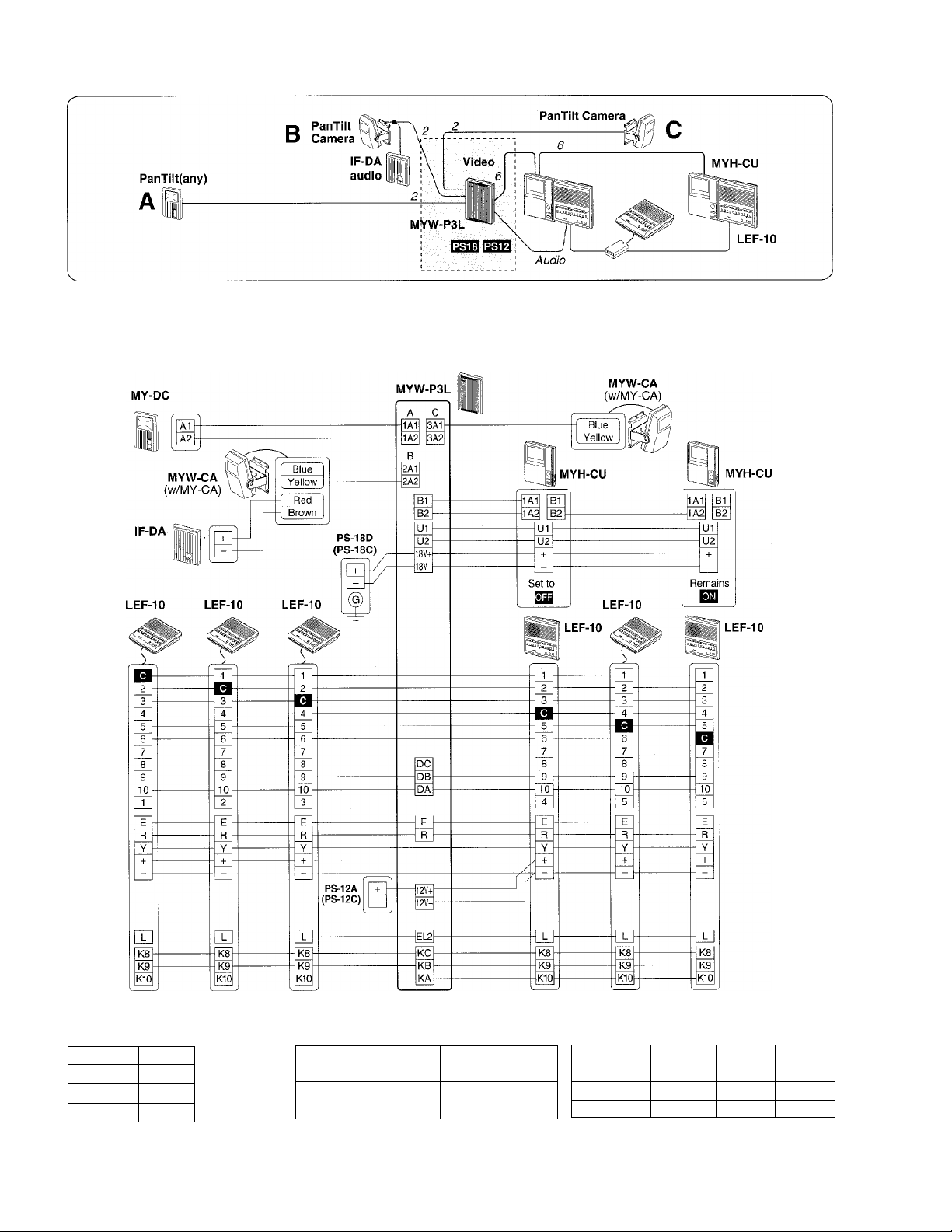
LEFT-10 3-PanTilt entry system
MYW-P3L provides LEF-10 system with max. 3 PanTilt video doors, locating MYH-CU monitor 1 or 2 max.
75m, 250’ away. The door camera can either be PanTilt door MY-DC, etc., MY-CA camera in MYW-A
overhead enclosure, with audio IF-DA or camera alone. Locate MYW-P3L adaptor in the middle point of LEFsystem together with 2 power supplies, audio and video.
I Wiring distance
From MYW-P3L to
2 power supplies
Diameter 1.0mm
Distance
AWG
Distance 16’
18AWG
5m
From MYW-P3L to PanTilt camera (any)
Diameter 0.65mm
Distance
AWG 22AWG
Distance 165’
50m 70m
0.8mm 1.0mm
20AWG 18AWG
230’ 330’
8-
100m
From MYW-P3L to farthest MYH-CU monitor
(1 or 2-monitor)
Diameter 0.65mm 0.8mm
Distance
AWG
Distance 115’
35m 50m
22AWG 20AWG 18AWG
150’ 250’
1.0mm
★ For 2-monitor system only, double
wires on -1-, - terminals between MYW-
P3L and MYH-CU’s.
75m
Page 9

MY-CU with 3 PanTilt cameras (w/ MYW-P3CB)
TD-12H
This is an expanded MY-CU system that includes max. 3
PanTilt cameras. Intercom can be either IE Series or
TD-H/A or B.
★ Locate MYW-P3CB and power supplies in the middle
point of using intercom system.
MYW-P3CB
MYH-CU MYH-CU
Wiring
PS-18D(18C)
power supply
PanTilt door 1 -
Camera 3 -
IVIYW-P3CB MYH-CU
2-
2--
DE-UR 1
— DE-UR 2
.6(8)
MYH-CU
ff
6(8)
N
r
- Intercom(audio from door 1)
■ lntercom(do, door 2)
■ lntercom(do, door 3, unused)
-9-
1
/
Diameter
Distance
AWG 22AWG
Distance
•
From MYW to farthest MYH-CU monitor
(1 or 2-monitor)
Diameter
Distance
AWG 22AWG
Distance
r For 2-monitor system only, double wires on 4-, -
terminals between MYW-P3CB and MYH-CU’s.
From MYW to PS-18D(18C)
Diameter
Distance
0.65mm
50 m 70m
165’ 230’
0.65mm 0.8mm
35 m 50m
115’ 150’
1.0mm
5m
0.8mm
20AWG
20AWG
AWG
Distance
1.0mm
100m
18AWG
330’
1.0mm
75m
18AWG
250’
18AWG
16’
Page 10
MOUNTING
---------------------
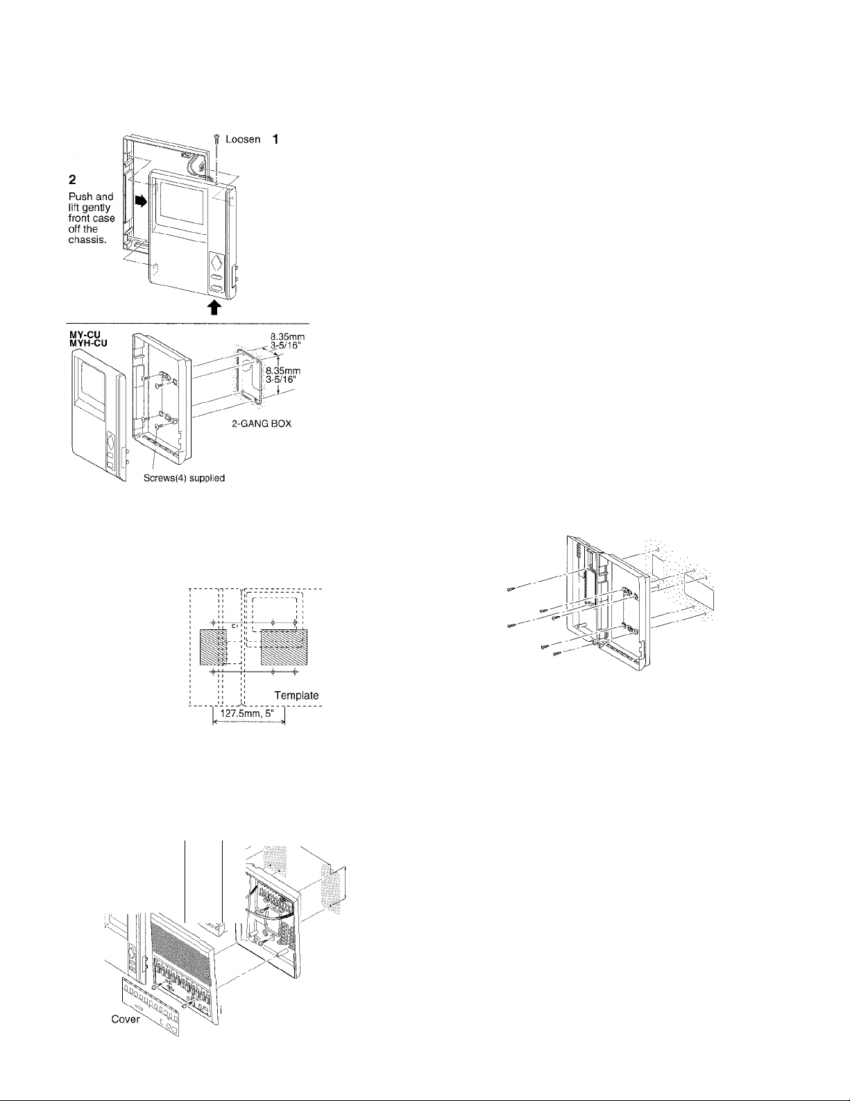
I Mounting MY-CU and MYH-CU
To mount the MY(H)-CU monitor, separate the terminalsmounted chassis from front case.
1. Loosen a screw on top of front case.
Press on bottom, right hand, and the front case slightly
moves up.
2. Then, press on center of left side, which unlocks from
chassis.
3. Lift gently front case, then it separates.
4. Disconnect video-monitor. Pull off the holder and set
monitor aside.
5. Attach chassis to wall at 4 points.
6. Make wire terminations directly on 6 screw terminals.
7. On MY-CU only, wire with jumpers on audio terminals
D1, D2 & E.
8. Pin the holder, reconnect and mount front case, justly
aligning to lock.
★ Do not connect any wires at any other point than on
terminals.
Mounting with intercom
For IE-1GD(U),
fE-2AD(U)
or TD-H/A or B template supplied to wall.
Two unit or box centers
For IE-8MD
and IE-8HD intercom
chassis
MY-CU
MYH-CU
Chassis
Before actually mounting the unit, attach the supplied template to wall. For MY-CU/IE-8MD
combination, attach two chassis to wall. First, mount the intercom chassis (or bracket) to wall or single
gang box, and MY-monitor chassis can adjustably be mounted to its right side.
203 mm, 8" measured between
Chassis
MYH-CU
monitor 3~5 cm,
11
IW
./1
A K two unit or box centers.
83.5 mm,
3-5/16"
• For MYH-CU and LEF-5,10,10S
Mount MYFI-CU to the left of LEF-5,
10, 10S intercom, keeping a space of
3 ~ 5 cm (1-1/4" ~ 2") for brightness/
contrast adjustment.
LEF-5, 10, 10S
ntercom
Chassis
-10-
Page 11

OPERATIONS on MY-CU & MYH-CU
I MY-DC, DG image viewing area
j : when camera is panned and tilted fully
□ : when camera is in still position.
-180cm(6’)-
Door camera
tilts down
Door camera
pans to right
Backlight control & Monitor buttons
Video monitor
When an image of entry is on the monitor, move door camera up
or down, side to side. Press on each edge of diamond-shaped
pad, and door camera is panned and tilted to view max. 90cm
high X 180cm wide (3’ H x 6’ W) on the monitor screen.
Backlight control button literally adjusts to brighten image of
entry strongly backlit or when the entrance area is dim day or
night. Monitor button views image of entry handsfree for 2-1/2
minutes (approx.). Press “Monitor” to turn off, or to view image of
2nd and 3rd entry.
Pan/tiit control
Brightness
Contrast
Monitor
PanTilt door station cail, monitor-activating
When a PanTilt door station has called, it turns on MY-CU and
MYH-CU sub-monitor(s). The image is kept on for approx. 45
Chime,
Call tone
seconds.
-11 -
Page 12

BEFORE ASKING FOR REPAIR
★ In case the system does not provide a satisfactory performance, possible causes may be; Unplugged? Disconnected wire?
Shorted wire? Consult the dealer or distributor that you purchased the product from.
★ Refrain from spraying water at the door staton directly, regardless that the unit Is designed to be weather-resistent.
★ Clean your MY-CU equipment by a soft cloth dampened with neutral household cleanser.
★ When the temperature outside lowers rapidly (after rain, etc.), the camera lens may be fogged and offer a dim Image at the
video monitor. This is not a malfunction, and will return to normal shortly.
I SPECIFICATIONS
Power source DC 18V on MY-CU
Use a PS-18D power supply (PS-18C in North America).
Current consumption
System
Max. 0.9A 0.4A 1.7A
Standby 0.12A
Video monitor
Scanning line
PanTilt door capacity
1 door
2 doors MYW-P3CB (for IE, TD-H/A or B)
3 doors MYW-P3L (LEF)
Wiring Use 6 or 8-conductor (non-twisted) cable between monitors with no extra wires nor reconnections.
To Pantilt door
MY-DC MY-CU
2 cond. (parallel)
0.65mm^
0.8mm
1.0mm 95
22AWG 165’
20AWG 230’
18AWG
MY-CU
lE-IGD(U), IE-2AD(U), IE-8MD, TD-H/Aor B, MYW-P1L (LEF)
50 m
70m
100m
330’
----------------
MYH-CU 3-monitor
OA
4” direct view flat CRT
525 lines
2 monitors
MY-CU MYH-CU
0.65mm.^ 35m
0.8mm ÿ 50m
I.Omm^ 75m
22AWG
20AWG
18AWG 250’
0.12A
115’
160’
Pan/tilt viewing area shown by dotted line
4-,
130cm
(4'3")
Camera
center
6cm 50cm (20”)
' 3 monitors
MY-CU MYH-CU
0.65mm ^ 17m
0.8mm.# 25m
1.0mm(#
22AWG
20AWG
18AWG
2ecm (If)
200cm (67’)
171cm (5’8’
90cm (36’’)
-122cm (4’)
110cm (3’8’
12cm (5”)
45 m
55’
80’
145’
MYH-CU
MY-DC/DG
157cm (22”)| 66cm (26”) i57cm (22”)|
c
---------------
1-180cm (6’)(
: Viewing area of camera in stili position
3 monitors
MY-CU MYH-CU
Wires on each -1-, - are doubled.
0.65mm #
0.8mm .#
1.0mm (f
22AWG
20AWG 160’
18AWG 250’
-----------------
MYH-CU
35m
50m
75m
115’
0cm
50cm
(20”)
-i
Dimensions (H x W x D)
Weight (approx.)
This equipment has been tested and found to comply with the limits for a Class B digital device, pursuant to Part 15 of the FCC Rules. These limits are designed
to provide reasonable protection against harmful interference in a residential installation. This equipment generates, uses, and can radiate radio frequency
energy and, if not installed and used in accordance with the instructions, may cause harmful interference to radio communications. However, there is no
guarantee that interference will not occur in a particular Installation. If this equipment does cause harmful inteference to radio or television reception, which can
be determined by turning the equipment off and on, the user is encouraged to try to correct the interference by one or more of the following measures:
• Reorient or relocate the receiving antenna. • Connect the equipment into an outlet on a circuit different from that to which the receiver is connected.
• Increase the separation between the equipment and receiver. • Consult the dealer or an experienced radio/TV technician tor help.
-t*
•t-
Aiphone warrants its products to be free from defects of material and workmanship under normal use and service for a period of two
years after delivery to the ultimate user and will repair free of charge or replace at no charge, should it become defective upon which
-t-
4*
examination shall disclose to be defective and under warranty. Aiphone reserves unto itself the sole right to make the final decision
4-
whether there is a defect in materials and/or workmanship; and whether or not the product Is within the warranty.
-t-
4-
This warranty shall not apply to any Aiphone product which has been subject to misuse, neglect, accident, or to use in violation of
4-
instructions furnished, nor extended to units which have been repaired or altered outside of the factory. This warranty does not cover
4*
4*
batteries or damage caused by batteries used in connection with the product.
4-
This warranty covers bench repairs only, and any repairs must be made at the shop or place designated in writing by Aiphone.
44-
Aiphone will not be responsible for any costs incurred involving on site service calls.
44-
Aiphone Co., Ltd., Nagoya, Japan
Aiphone Corporation, Bellevue, WA, USA
IVIY-CU-I(E) 0595D
210 mm X 155 mm x 50 mm. 8-1/4” H x 6-1/8” W x 2” D
MY-CU 1.0 kg (2.20 lbs.) MYH-CU 0.9 kg (1.98 lbs.)
WARRANTY
& AIPHONE
— HOME, BUSINESS. INDUSTRY.
-12
**}*-i*-^-.i*
-h
COMMUNICATION SYSTEMS
Printed in Japan (E)
 Loading...