

Page 1
83659100 05971
MK Series DOOR SENTRY
VIDEO ENTRY SECURITY INTERCOM
Models: MK-1MD Main audio/monitor station
MK-1MD/A
INSTALLATION & OPERATION MANUAL
Before actually installing MK-1MD(/A), the contents of this Manual
must be thoroughly read and understood.
A PRECAUTIONS ON INSTALLATION & WIRING
® AlPHONE
/iy: WARNING
(Negligence could result in death or serious
injury to people)
A,: GENERAL PRECAUTIONS
General prohibitions.
(§): Prohibitions to subject the unit to water.
A WARNING
1. Do not change or modify MK-1 MD(/A) equipment. ^
2. Do not connect any power source other than specified to
terminals +, - on MK-1 MD(/A).
Doing so can cause fire or damage the unit. ^
3. The MK-1 MD(/A) equipment must not be exposed to water
or any other liquid, rg)
4. Do not open MK-1MD(/A) monitor unit. The high voltage is
inside.
5. Make sure wires are connected properly before plugging in
the power supply. ^
6 Keep AC outlet away from moisture and dust.
7. Do not put any forcible strength on the monitor of MK-
1 MD(/A). It can cause injury.
CAUTION
A
1. Do not install or make any wire terminations while power
supply is turned on. It can cause electrical shock or
damage the unit.
2. Mount the MK-1 MD(/A) monitor on wall in a convenient
location, but not where it could be bumped or jarred.
A : CAUTION
(Negligence could result in injury to people or
damage to property)
Prohibitions to dismantle the unit.
Q: Take the unit to earth ground
3. Do not install MK-1 MD(/A) components in any of the
following locations, as it may cause the system to
malfunction;
- High or extreme cold temperature area: under direct
sunlight, near equipment that varies in temperature,
in front of air-conditioner, inside a refrigerated area,
etc.
- Places subject to moisture or humidity extremes.
- Places subject to environmental conditions, such as
oil, dust, chemicals, salt, etc.
- Places subject to constant vibration or impact.
A GENERAL PRECAUTIONS
1. MK-1 MD(/A) equipment, except for MK-DS(/A), is
designed for indoor use only. Do not install outdoors.
2. MK-1 MD(/A) system is not operable during a power
failure.
3. In areas where broadcasting station antennas are close
by, intercom system may be affected by radio frequency
interference.
4. Keep all DC wiring at least 30cm, 20” away from
AC 100 ~ 240V wiring, fluorescent lighting, or dimmer
switches. Otherwise, cross AC wiring at a 90° angle.
Page 2
SYSTEM OUTLINE & COMPONENTS
MKS-1E DOOR SENTRY is a set with one monitor and one video door station for audio and video door answering
and door release.
A second monitor or audio-only handset can be added.
■ Package contents
MKS-1E, AC 120V (USA) or AC 220-240V
Boxed set with Main monitor MK-1 MD(/A),
Door station MK-DS(/A) & Power supply
(PS-18YC/AorPS-18YE)
Mounting bracket
Packet of screws
installation & Operation Manual
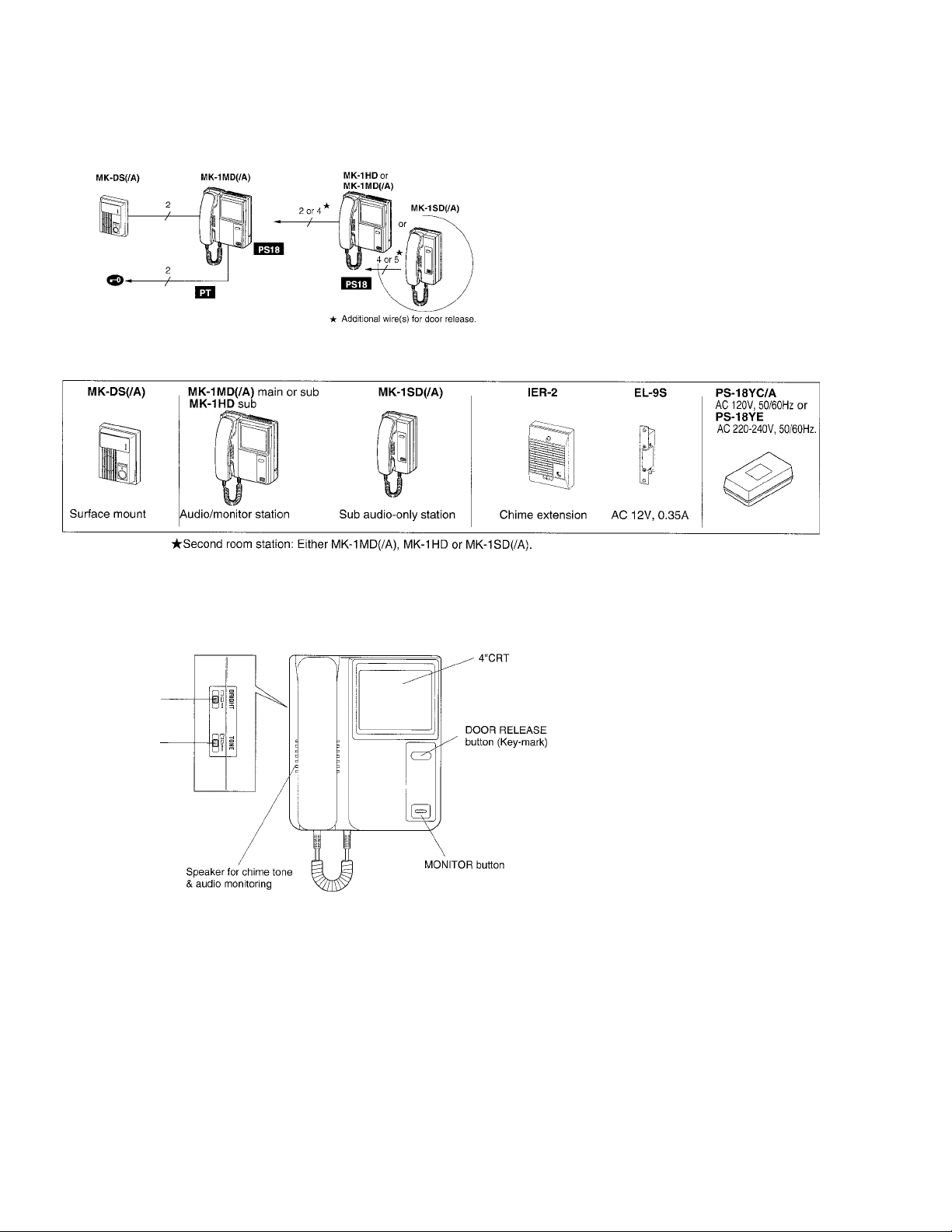
Components available
• Video door station • Monitor & audio stations
• Call extension • Door strike
Power supply
NAMES AND FEATURES
BRIGHT control
TONE control
each 3 positions
MK-1MD(/A)
■ Features
☆ One door and one monitor system,
expandable with second audio/monitor
or audio-only sub station.
☆ Wide angle door station: Views 70cm
vertically and 100cm horizontally (70°V
x90°H).
☆ Camera angle adjuster on MK-DS(/A)
(Turns up camera angle by 14°).
-2-
Page 3
WIRING ----------------------------------------------------
■ Cable requirements
• Use a parallel conductor cable.
Coaxial cable should not be used.
• When existing chime wires are used, it is possible that the wires
may contain AC voltage current. Locate and remove the bell
transformer before actually connecting MK-DS(/A).
• Extra pair(s) in the installed cable can affect image quality, and
must be terminated with a 120 ohm resistor at each end at both
MK-DS(/A) and MK-1 MD(/A). Otherwise, double up the wires
onto each terminal.
Parallel cable Coaxial cable
YES
120 ohm
NO
120 ohm
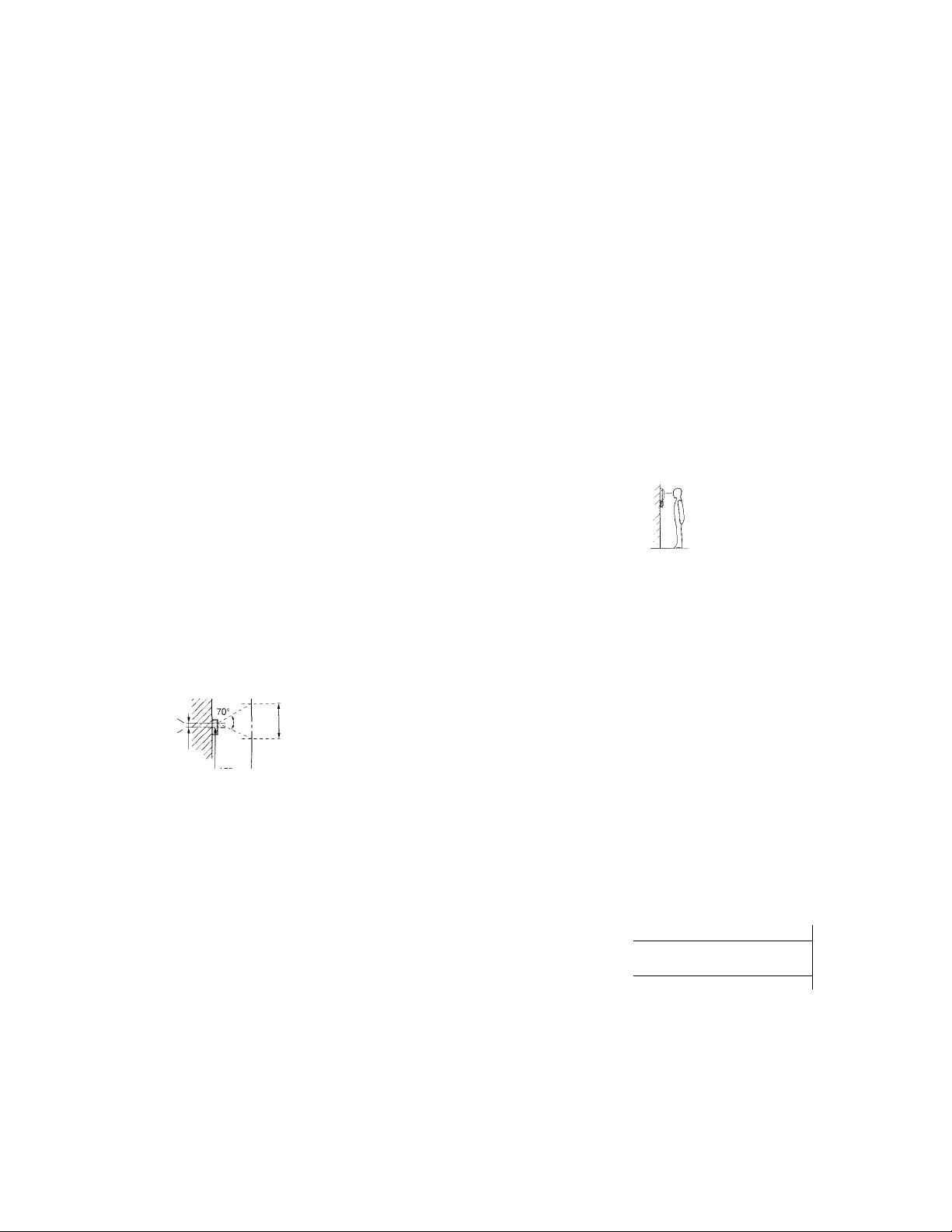
I Installation location
MK-DS(/A)
MK-DS(/A) employs CCD camera and the performance can be affected by
bright direct light, such as strong sunlight, gate light, or street or porch
light which comes directly into the camera lens.
MK-1MD(/A)
Mount the video monitor so that the center of the monitor screen comes to
the eye level of the user.
I When camera height is too low
MK-DS(/A) is equipped with a camera-angle adjuster on the back of the
unit. Pull the lever down to adjust the camera angle upward by 14°.
When camera is positioned horizontally;
188 cm(6’ 2")
MK-DS(/A)^
center
3 cm
(1-3/16”)^
70 cm (2' 3")
118cm(3’ 10”)
(20”)
When camera angle is upwardly adjusted;
Camera
center V
MK-DS(/A)"
center
3 cm
(1-3/16”)
MK-DS(/A)
- /x ■>'/,
MK-1MD{/A)
50 cm
(S')
-Strong
-light
-source
MK-DS(/A)
BACK VIEW
210cm(6’11"
|75 cm (2' 5")
-135 cm(4’ 5”)
50 cm (20’
100 cm (3’ 3”)
I When installing a second station
MK-1MD(/A) may have a sub station, either the same MK-1MD(/A)
monitor or MK-1SD(/A) handset. Locate the second station within
permitted distance of 100m, 330' from the camera. Wire second inside
station directly to first inside station.
• Video-impedance matching (on SW1): In dual monitor system only,
change initial A setting to B (HIGH) position on MK-1 MD(/A) mainmonitor.
I Call extension
To hear the chime in a remote location, install an IER-2 speaker with 2
wires(NP) from any inside station. One IER-2 per station.
I Door strike
MK-1 MD(/A) monitor provides a dry closure contact for door strike. Use
Aiphone's EL-9S, AC 12V, 0.35A, powered by AC transformer PT-1210N
in USA, or a strike appropriate for the door.
-3-
'50 cm (20 )
^ 2
J /
100m, 330’
/ MK-1MD(/A)
MK-1MD(/A) ^
4 or 5
---------
^ MK-1MD(/A)
2or2x2 in
^MK-1MD(/A)
orMK-IHD
MK-1SD(/A)
Page 4

Wiring diagrams
• Single MK-1 MD(/A) system
MK-1MD(/A)
MK-DS(/A)
SW1 Q
(Video impedance
-matching)
1
2
3
5
EL-9S
AC trans.
PT-1210N (USA)
* Terminals 1-5 are for MK-1SD(/A) audio station.
NP: Non-polahzed P: Polarized. T - Parallel cable
: PS-18YC/A or PS-18YE (specified)
Do not run door release & audio/video wires in
the same jacketed cable.
A
Red(+)
BlackH
• Two-monitor system
MK-DS(/A) MK-1MD(/A)
I Video-impedance matching
The SW1, initially set to A position,
must not be changed except to B
position on the first MK-1MD(/A)
station of 2-monitor system.
S'AT 1
□
B
H
MK-1MD(/A) or MK-1 HD
Back View
j MOUNTING
--------------------------------------
■ MK-1MD(/A)
On back of the unit, mounting bracket is attached.
1. Mount the bracket to single-gang box or wall.
2. On the back, terminate parallel wires on A1, A2 terminals.
3. Connect 18V DC output wires from PS-18Y power supply.
Red to (-I-), Black to (-).
4. Mount MK-1 MD(/A) monitor onto the bracket, aligning at
marks.
Pull down until it firmly locks.
5. Plug PS-18Y into an open AC outlet.
PS-18YC/A(AC 120V), PS-18YE (AC 220-240V)
Install the power supply within
1.9m, 6’3” of the monitor.
Do not attempt to extend the DC
side of the power supply. If
necessary, extend the AC side
with an extension cord.
PS-18YC/A
orPS-18YE
Bracket
Screw (2)
Page 5

OPERATIONS on MK-1MD(/A)
MK-1MD(/A)
Key-mark
/
MONITOR
Receiving a door cali:
Communication:
Audio / visual monitoring:
MK-DS(/A)
When call button is pushed on MK-DS(/A), it activates
4-tone chime and image at inside monitor(s). Simply
lift handset to reply within 30 seconds.
The communication is timed for 2-1/2 minutes.
Press MONITOR button to extend another 2-1/2 minutes.
★ Monitor image times out in 30 seconds after called.
1
o
d
I
MK-1MD(/A)
In standby mode, press MONITOR button to activate both
audio & video of door station. Audio is heard
through open voice speaker.
Call extension speaker
IER-2 allows the chime to be heard at a remote location.
Volume is adjustable to 3 positions.
Controls
On MK-1MD(/A):
MONITOR (on front).
BRIGHT & TONE, chime & audio volume,
each 3 positions (on left side).
Second Audio/monitor or Audio-only station
on the other monitor.
MK-1SD{/A)
MK-1SD(/A)
The second monitor operates exactly the same as main
monitor. MK-1SD(/A) can be used for door answering and
door strike. There is no calling between the inside
stations.
★ If someone at hearing the other station is answering
the door, hang up handset.
Page 6

TECHNICAL PRECAUTIONS ----------------------------------------------------------------------
Temperature: MK-1MD(/A) is rated to operate between temperatures 0"C ~ 40°C (+32‘F ~ +104T),
It takes approx, one second for system to recycle.
Image may vary when the Key-mark button is held down to activate door strike. This is not a malfunction.
MK-1 MD(/A) monitor can work with MY Series door components:
MY-DS, MYW-CA (w/MY-CA inside) and MYW-BA long-distance adaptor.
Image through overhead MYW-CA may vary, but it is not a malfunction.
Do not operate MONITOR button and plug in at the same time. It will create a continuous high-pitched tone, and can be reset by momentarily
unplugging power supply.
Cleaning: Clean MK-1MD(/A) with a soft cloth dampened with neutral household cleanser. Do not use any abrasive cleaner or cloth.
SPECIFICATIONS
Power source:
Power supply:
Image viewing area;
When camera is in horizontal position;
When camera is upwardly adjusted;
Communication:
MK-DS(/A) camera unit:
MK-1MD(/A) monitor:
Scanning lines:
Minimum illumination;
Door release contact capacity:
Wiring;
Wiring distance;
Dimensions & weight:
MK-1MD(/A): DC 18V, 0.8A. 0.04A (standby).
PS-18YC/A, AC 120V, 50/60HZ.
PS-18YE, AC 220-240V, 50/60HZ.,
each with secondary output: DC 18V, 1.2A.
70cm V X 100cm H (2’3” V x 3’3” H)
75cmV X lOOcmH (2'5” V x 3’3” H)
Call-in: Image is on 30 sec.
Communication: 2-1/2 min. timed.
Extend with MONITOR button.
Common talk between rooms (hang up either handset)
CCD camera with infrared LEDs.
4 inch direct view flat CRT
525 lines.
Less than 1 Lux at 50cm, 20” distance.
AC 12V, 0.4A (dry closure contact EL, EL).
2 wires parallel, non-polarized (Aiphone #841802 in USA).
MK-1MD(/A) to MK-DS(/A);
0.65mm ji I.OmmjS
50m 100m
22AWG 18AWG
165’ 330’
Models H W D (mm) Weight (approx.)
MK-DS(/A) 130 98 37.5 230g
MK-1MD(/A) on HD 210
MK-1SD(/A) 210 100 74 415g
This equipment has been tested and found to comply with the limits for a Class B digital device, pursuant to Part 15 of the FCC Rules.
These limits are designed to provide reasonable protection against harmful interference in a residential installation. This equipment
generates, uses, and can radiate radio frequency energy and, if not installed and used in accordance with the instructions, may cause
harmful interference to radio communications. Flowever, there is no guarantee that interference will not occur in a particular installation. If
this equipment does cause harmful inteference to radio or television reception, which can be determined by turning the equipment off and on,
the user is encouraged to try to correct the interference by one or more of the following measures:
• Reorient or relocate the receiving antenna. • Connect the equipment into an outlet on a circuit different from that to which the receiver is
connected • Increase the separation between the equipment and receiver. • Consult the dealer or an experienced radio/TV technician for
help.
-!•
-!•
•S*
Aiphone warrants its products to be free from defects of material and workmanship under normal use and service for a period of two
-!•
-F
years after delivery to the ultimate user and will repair free of charge or replace at no charge, should it become defective upon which
examination shall disclose to be defective and under warranty. Aiphone reserves unto itself the sole right to make the final decision
whether there is a defect in materials and/or workmanship; and whether or not the product is within the warranty.
•F
This warranty shall not apply to any Aiphone product which has been subject to misuse, neglect, accident, or to use in violation of
•F
-F
instructions furnished, nor extended to units which have been repaired or altered outside of the factory. This warranty does not cover
•F
batteries or damage caused by batteries used in connection with the product.
•F
•F
This warranty covers bench repairs only, and any repairs must be made at the shop or place designated in writing by Aiphone.
-F
Aiphone will not be responsible for any costs incurred involving on site service calls.
-F
*F
•F
Aiphone Co., Ltd., Nagoya, Japan
Aiphone Corporation, Bellevue, WA, USA
186 78 1,130g
WARRANTY
H W D
5-1/8”
8-1/4” 7-5/16” 3-1/16”
8-1/4”
3-7/8”
4”
1-1/2”
3” 0.91 lbs.
COMMUNICATION SYSTEMS
®
AIPHONE
Weight (approx.)
0.51 lbs.
2.49 lbs.
•i-
•i*
•i-
HOME, BUSINESS, INDUSTRY.
MK-1MD-KE) 0597B
Printed in Japan (E)
 Loading...