

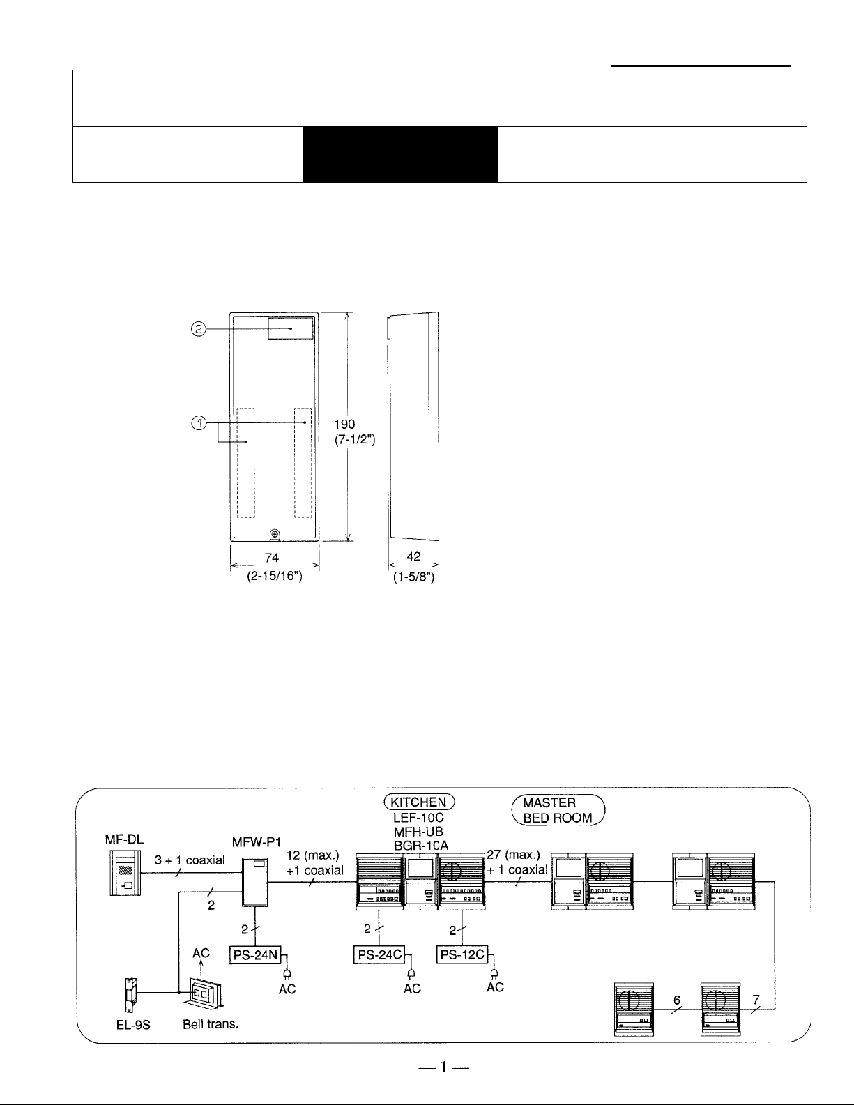
Page 1
LEF 1-CAMERA ADAPTOR I
^ Model;
INSTRUCTIONS
NAMES AND FUNCTIONS
MFW-P1
83967700 1291( ® AlPHONE
(1 -camera video adaptor for LEF
system) ^
0 Terminal section
@ Reset switch
Mounting accessories;
¿S'
V V
SCREW (2) WOOD SCREW (2)
FEATURES & LAYOUT
* Accepts one video door station for your LEF system (LEE, LEF-B & LEF-C).
* Includes control for door release.
* Surface-mounts to single-gang box.
* Max. 3 inside video monitors powered by a single power supply can be expanded to max. 10 video
monitor system, (one PS-24N power supply for every 3 video monitors)
Page 2
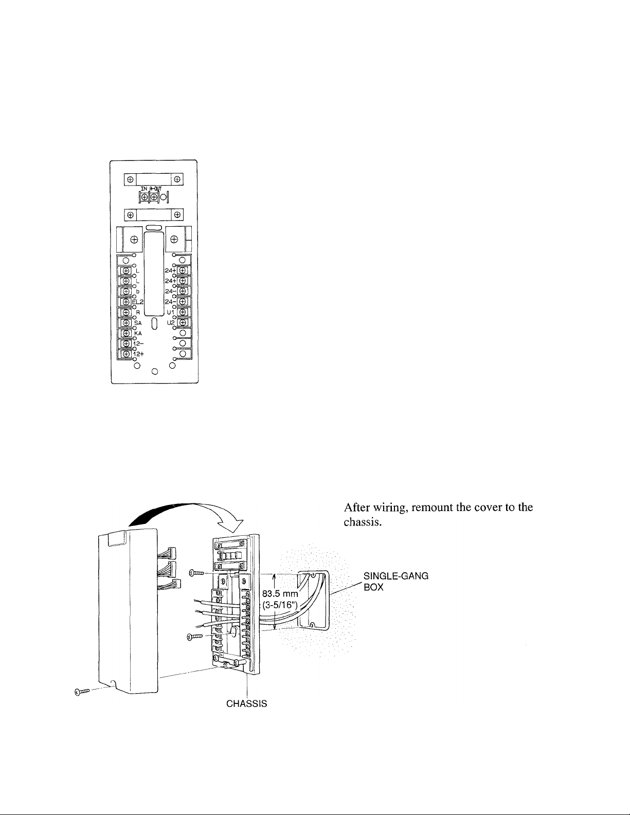
INSTALLATION
a
(1) ACTUAL TERMINAL LOCATION;
(2) WALL-MOUNTING;
IN
R-OUT
R
EL2
12+
KA
SA
24+
U1
U2
12-
24-
: for connecting coaxial cable to
MF-DL.
: for connecting coaxial cable to
MFH-UB.
: for door release.
: for illumination lamp control.
: for occupied LFD.
: for door release control.
; for communication power supply.
: for camera control.
: for calling detection.
: for power supply.
: for input control.
: for output control.
Attach the chassis to SINGLE-GANG BOX
with the supplied 2 screws.
Page 3

WIRING DIAGRAM
(1) LEF-10C video system (intermixed system)
This diagram illustrates LEF-IOC master stations (max. 3) can reply to door station call. LE-C subs
can call and communicate with masters Nos. 1 &2 (max. 2). Any station can receive all call and
background music.
NOTES;
MFH-UB video monitors:
The 3rd MFEl-UB is optional. Up to 3 video monitors can be powered by a single PS-24N.
Max. 10 video monitors per system. Install a PS-24N for MFH-UB Nos. 4 ~ 6, and another PS-
24N for MFH-UB Nos. 7 ~ 9.
Leave [+] terminal unconnected between MFH-UB Nos. 3 and 4, and between Nos. 6 and 7.
Leave impedance matching plug in on last MFH-UB only.
For door station call-in, max. 3 master stations can be receptionists, while max. 2 master
stations can be connected to each inside sub station.
INSTALLATION
When mounting MFH video monitor, be sure to locate MFH to the left of the LEE unit, in order
not to pick up noise from the CRT.
__
Page 4

(2) LEF-10 VIDEO SYSTEM (Without BGR-10A Music Center)
This illustrates LEF-10 video system without background music capability.
Door station call-in can be received at max. 3 room stations.
As to LE-A, AN room sub station connect to not more than two masters.
NOTES;
Connect 3 intercom wires from MF-DL to LEF-10 directly.
Coaxial cable; 5C-2V or RG-59/U with solid copper core and copper braid.
Leave impedance matching plug in on last MFH-U only.
INSTALLATION
When mounting MFH video monitor, be sure to locate MFH to the left of the LEE unit, in order
not to pick up noise from the CRT.
Page 5

(3) When installing an iliumlnation lamp;
MFW-P1
1-CAMERA ADAPTOR
3
OPERATIONS
When MF-DL video door station calls in;
When call button is pressed on MF-DL, electronic mono tone (or chime tone, if connected to
BGR-lOA) sounds and image appears on inside video monitors.
Reply within 45 seconds.
Depress a corresponding selector button, and communicate by pressing TALK button.
To listen, release TALK button.
Depress DOOR RELEASE button (Door release can be activated also in non-communicating mode).
After communication, depress OFF button, and the image goes off.
(the image is on for approx. 2 minutes and half after station selection).
Monitoring;
To monitor the outside, press VIDEO MONITOR button, and the image appears for approx. 2 minutes
and half.
When system does not work properly, press reset switch on MFW-Pl adaptor and restart.
Page 6

SPECIFICATIONS
* Power source DC 24V & DC 12V. Use power supplies PS-24N & PS-12C or PS-12A.
* Current consumption 0.6A (max.) (without video monitor included).
Less then 0.1 A (standby).
* Wiring Max. 12 wires & one coaxial cable (to BGR-IOA/MFH-UB/LEF-IOC)
* 4 wires & one coaxial cable (to MFH-UB) (2 unconnected)
* 3 wires (to BGR-lOA)
3 wires & one coaxial cable (to MF-DL) (2 unconnected)
3 wires (to MAW-B relay)
* Wiring distance ■ Between MF-DL & MFW-Pl;
COAXIAL CABLE
DIAM./AWG
DISTANCE
■ Between MFW-Pl & MFH-UB;
COAXIAL CABLE
DIAM./AWG
DISTANCE
Between MFW-Pl & PS-24N;
■
DIAM./AWG 1.0 mm 18AWG
DISTANCE
* Dimensions & weight
(H X W X D)
Aiphone warrants its products to be free from defects of material and workmanship under normal use and service for a period of
one year after delivery to the ultimate user and will repair free of change or replace at no charge, should it become defective
upon which examination shall disclose to be defective and under warranty. Aiphone reserves unto itself the sole right to make
the final decision whether there is a defect in materials and/or workmanship; and whether or not the product is within the
warranty.
This warranty shall not apply to any Aiphone product which has been subject to misuse, neglect, accident, or to use in violation
of instructions furnished, nor extended to units which have been repaired or altered outside of the factory.
This warranty does not cover batteries or damage caused by batteries used in connection with the product.
This warranty covers bench repairs only, and any repairs must be made at the shop or place designated in writing by Aiphone.
Aiphone will not be responsible for any costs incurred involving on site service calls.
190 X 74 X 42 (mm); 7-1/2"
Approx. 270g (0.60 lbs.).
WARRANTY
5C-2V
0.65 mm
150 m 495'
5C-2V
0.65 mm
75 m 245'
10 m 33'
X 2-15/16" X 1-5/8"
RG-59/U(20GA)
22AWG
RG-59/U(20GA)
22AWG
Aiphone Co., Ltd. Nagoya, Japan
Aiphone Corporation, Bellevue, WA, USA
MFW-P1-I(E) 1291C
6 —
o
COMMUNICATION SYSTEMS
AIPHONE
HOME, BUSINESS, INDUSTRY.
Printed in Japan (E)
 Loading...