

Page 1
832333 0990 ©
VIDEO MONITOR
® AlPHONE
Models;
V
INSTRUCTIONS
NAMES AND FUNCTIONS
MFH-U
MFH-UB
-d)
-©
(Video monitor, surface-mount)
(Video monitor, semi-flush mount)
________________
n
-©
J
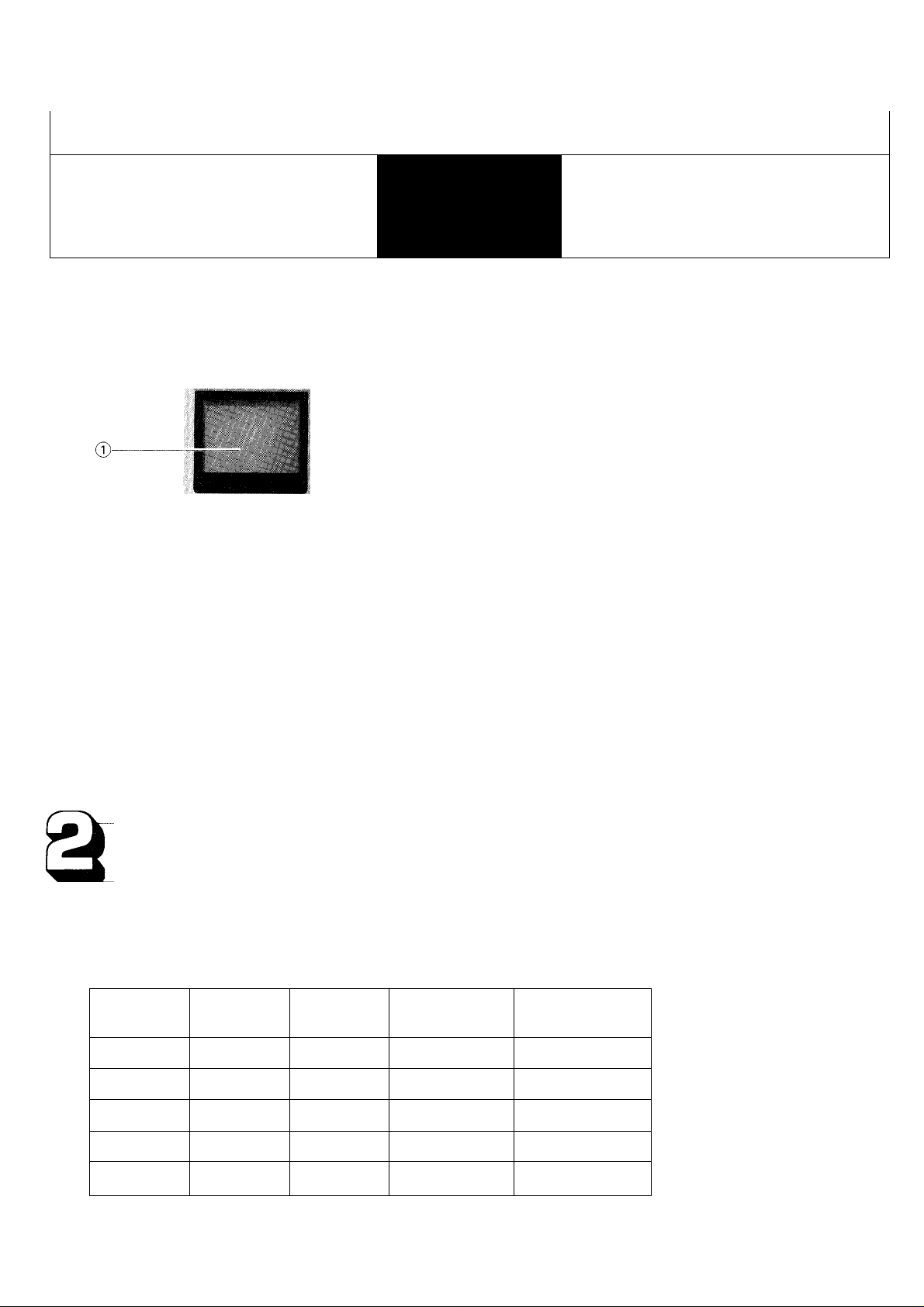
MFH-U (surface-mount)
(T) Video monitor
@ MONITOR button
d) Brightness control
@ Contrast switch (3-level)
MFH-UB (semi-flush mount)
Mounting accessories;
screw (4):
4mm dia x 25
Wood screw (4):
4.1 mm dia. x 1 6
FEATURES
* MFH-U/UB are video monitors for use with IE series Chime Tone Intercoms; lE-IAD(U), lE-IGD(U) & IE-2AD(U) and
LEF/LEF-B Loudspeaker Intercom Systems.
* Door answering by intercom with caller’s image on video monitor.
* Video monitoring of up to 3 entries (either MF-D/DL video door station or MFW-CZ camera) from any inside video monitors.
* Max. 10 video monitors per system.
(*) Shows numbers of camera
installable when video door
station is used to full capacity.
SYSTEM
lE-lAD(U)
lE-lGD(U)
DOOR
1
1
ROOM
1
3
VIDEO DOOR
STATION
1 (max.)
1 (max.)
SURVEILLANCE
CAMERA (* *)
2
2
IE-2AD(U)
LEF
LEF-B
Note; Video door station can also be audio only door station plus surveillance camera.
2
3
3
3
8
8
2 (max.)
3 (max.)
3 (max.)
1 —
1
0
0
Page 2

PREINSTALLATION AND OPERATION TIPS AND PRECAUSTIONS
*
Installation;
Never connect any terminals on the units to an AC power line.
©
When mounting the MFH-U/MFH-UB units in place of existing bell or chime, be sure to discon
nect all wires from the present transformer.
Do not open the front cover of MFH-U/MFH-UB units, without first unplugging the power supply
from the AC outlet. The high voltage is loaded on the monitor unit inside.
Do not drop or apply any undue shock to the unit which may damage the picture tube.
Avoid running the connecting wires through doors, windows or in areas that may cause pinching
or disconnect.
The MFH-U/MFH-UB units must be installed in as dry and dust-free an environment as possible.
Installation location requirements;
Do not install MFH-U/MFH-UB video monitors in a place where they are
directly exposed to; direct sunlight, water, air conditioner, heater, chemicals,
frost, iron dust, vapor, etc.
Determine the installation height so that the center of the MFH-U/MFH-UB
@
video monitors will be at the convenient eye level: adults’ average height minus
100 mm (4").
Maintenance;
Clean your MFH-U/UB equipment with a soft cloth dampened with neutral
household cleaner. Never use lacquer thinner, benzine, etc.
NEVER
Adult's average I
height minus(
too mm (4")
System layout & components requirements;
IE-2AD(U)/MFH-U Video system;
DOOR/AREA
IE-2ADIU) IEH-1CD
MFH-U MFH-U
ROOMS
Ol
i:
-
^ r
i! ©
©d
Components;
MF-D, Video door station.
Surveillance camera:
(MFW-CZ, supplied by Aiphone. Can be
#(
■
ih
r
m'
E
IEH-1CD
MFH-U
used with lE-DA, etc. audio only door
station).
lE-lAD(U), Main room station.
lE-lGD(U), -doIE-2AD(U), -dolEH-lCD, Sub room station.
MFH-U, Video monitor, surface-mount.
MFW-P3: Video adaptor, surface-mount.
Components;
MF-DL, Video door station.
Surveillance camera:
(MFW-CZ, supplied by Aiphone. Can be used
with LE-D/DA audio only door station).
LEF-5, 10, lOS: Master station.
MFH-U: Video monitor, surface-mount.
LEF-5B, lOSB: Master station, semi
flush mount.
MFH-UB: Video monitor, semi-flush
mount.
MFW-P3: Video adaptor, surface-mount.
BGR-lOA: All call & BGM adaptor
for door station chime call-in.
- 2 -
Page 3

INSTALLATION
(1) lE/MFH-U surface-mounting to MBW-A back box;
lE-lGD(U)
IE-2AD(U)
Line A
To mount the MFH-U, remove the top screw in the case, and separate front case from the chassis, pushing the bottom, right
of front case upward, then the left side of the case to the right, and removing the connector. Attach the chassis to MBW-A
and reattach the front case. To mount IE intercom, attach mounting bracket to MBW-A and mount the unit onto the bracket.
Cut a hole 95 mm (3-3/4") high by 215 mm
(8-1/2") wide and 40 mm (1-9/16") deep into
the wall. Position the MBW-A box in the
wall, with the V-cut in the upper position, so
v-cut that line A crosses vertically with the floor.
MBW-A
(2) LEF/MFH-U surface-mounting (on gang boxes);
When mounting LEE master & MFH-U video
monitor side by side, be sure to locate
MFH-U to the left of LEF master, keeping
a space of 3 to 5 cm (1-3/16" to 2") for
brightness and contrast adjustment.
(3) LEF-B/MFH-UB semi-flush mounting to wall;
JUNCTION LEF-B
HARDWARE CHAVIS
-LEF-5B, -10SB
CHASSIS
First, separate each chassis from front case.
Mount the chassis with the supplied screws.
After wiring, reattach connectors and front
case to chassis.
To mount LEF-5B/10SB and MFH-UB units,
cut and open a hole of H: 206 x W: 306 (mm)
(H: 8-1/8" X W: 12-1/16"), keeping a space
of 3 to 5 cm (1-3/16" to 2") on each side.
Before installation, join together both LEFB and MFH-UB chassis by attaching a
junction hardware with 3 screws (supplied).
Attach two chassises with 4 wood screws
(supplied).
After wiring, remount front cases to each
chassis.
BUTTON-IDENTIFICATION
PLATE.
Page 4

WIRING DIAGRAMS
[ (1) IE-2AD(U) SYSTEM w/VIDEO MONITORING CAPABILITY;
The MFW-CZ camera (No. 3) must correspond each with video input terminals I 3 I (for coaxial cable) and
B3 (for video signal input) on MFW-P3.
Connect coaxial cable from MF-D thru MFW-P3 to terminal A on MFH-U.
In a system with more than one video monitor, remove impedance-matching plug on all video monitors,
except on the farthest monitor.
IE-2AD(U) can accept max. 2 video door stations, one each for lE-lAD(U) and lE-lGD(U).
¡COAXIAL CABLE CONNECTION;
COAXIAL ■ ■ COAXIAL
CABLE —
II
----------------
aI^^b
CABLE
MFH-U
5C-2V
RG-59/U (20GA)
11 mm (7/16")
3 mm (1 /8" 1
8.5 mm (5/16")
Fold back braided conductors in a manner that core
conductor be not bent nor shorted to braided
conductors.
Connect braided conductors
with clamp.
- 4 —
DO NOT REMOVE
THIS GROUNDING
TERMINAL.
Page 5

(2) LEF VIDEO SYSTEM WITH MONITORING CAPABILITY;
@ In a system with more than one video monitor, remove all the impedance-matching connectors, except at the
farthest monitor.
O When connecting PS-12A/PS-12C power supply, remove shorting links between
AV
12+ and ED-12-
-
MFW-P3 adaptor.
© For wiring connections between adaptors and door stations, please follow the table below for system's proper
functioning;
Door station No. 1 2 3 Camera/area No.
LEF door-assigned terminal 10 9 8
Camera-assigned terminal (MFW-P3) B1 B2 B3
BGR-lOA door station terminal DA DB DC Coaxial cable input
For calling detection (MFW-P3,BGR-lOA)
Video control (MFW-P3)
- do - (LEF)
For door release control (MFW-P3) LI
Coaxial cable input
I COAXIAL CABLE CONNECTION;
iMFH-UB
SA SB SC
KA KB KC
KIO K9 K8
1 2
5C-2V
RG-59/U(20GA)
8 mm (5/16
4 (3/16"
~r
8 (5/16"
- 5 -
L2
L3
3
3C-2V
RG-59/U(22GA)
® @
"^"^'8 (5/16")
I n 4 (3/16")
Fold back braided conductors in a manner that
core conductor be not bent nor shorted to
braided conductors.
From: video monitor
Fasten dips by pliers to hold
braided conductors.
1 2 3
1 2
3
Page 6

OPERATIONS
(ä
1. Receiving a call from door station;
Door station call-in is annunciated by chime tone and picture appears on video monitor.
Press a selector button with illuminated LED on LEF/LEF-B. Depress TALK button to talk and release to listen.
In IE system, simply pick up handset at any station to reply.
NOTES; (1) Reply within 45 seconds after chime tone sounds.
(2) Picture remains for approx. 2 minutes and half. If picture goes off, depress MONITOR button until you have
2. Video monitoring;
Depress MONITOR button on MFH-U/MFH-UB to turn on door station/camera N0.1
Depress MONITOR button again to have the picture of door station/camera No.2.
If a door station/camera N0.3 is installed, depress MONITOR button third time (if not installed, picture goes off).
The fouth pressing MONITOR button turns off the picture.
The fifth pressing returns to the No. I picture.
NOTES; (1) The picture goes off approximately 1 minute after MONITOR button is pressed.
(2) To monitor the other door station (s);
(3) When door station calls in while monitoring, the picture is switched to that of calling door station.
3. Adjusting brightness;
Turn the control to the right or upward to make the picuture
brighter.
4. Adjusting contrast;
The picture contrast may be adjusted to 3 levels as desired.
the picture of the calling door station.
The picture which comes on after last time MONITOR button is pressed, starts from the door station/camera
last monitored. If door station calls in after last monitoring, the next video monitoring starts from the door
station/camera No. I.
While communicating with one video door station, you can switch to the picture of the next door station, by
pressing MONITOR button on MFH-U/MFH-UB.
.STRONG-MEDIUMiSQFT
Cia
SPECIFICATIONS
*Power source:
*Current consumption:
*CRT:
^Scanning line:
*Wiring:
*Wiring distance
between MFW-P3
and MFH-U/UB:
^Dimensions:
*Weight:
Aiphone warrants its products to be free from defects of material and workmanship under normal use and service for a period of one
year after delivery to the ultimate user and will repair free of charge or replace at no charge, should it become defective upon which
examination shall disclose to be defective and under warranty. Aiphone reserves unto itself the sole right to make the final decision
whether there is a defect in materials and/or workmanship; and whether or not the product is within the warranty.
This warranty shall not apply to any Aiphone product which has been subject to misuse, neglect, accident, or to use in violation of
instructions furnished, nor extended to units which have been repaired or altered outside of the factory.
This warranty does not cover batteries or damage caused by batteries used in connection with the product.
This warranty covers bench repairs only, and any repairs must be made at the shop or place designated in writing by Aiphone. Aiphone
will not be responsible for any costs incurred involving on site service calls.
DC 24V, supplied by PS-24N power supply, (required for every three MFH-U/MFH-UB).
Max. 0.35A.
4 inch CRT, direct view and flat type.
525 lines.
One coaxial cable and 4 wires between MFH-U/UB’s and between MFH-U/UB’s and
MFW-P3.
Coaxial cable 5C-2V
Diameter 1.0 mm
Distance 75 m
MFH-U; (WxHxD) 155x210x50 (6-1/8" x 8-1/4" x2").
MFH-UB; (W X H X D) 150x240x73 (5-15/16" x 9-7/16" x 2-7/8").
MFH-U; Approx 1.1 kg (2.43 lbs.). MFH-UB; Approx. 1.2 kg (2.65 lbs.)
WARRANTY
: /darker/brighter
MFH-UB
Coaxial cable
AWG
Distance 250'
RG-59/U (20GA)
18 AWG
AIPHONE CO..LTD., NAGOYA, JAPAN
AIPHONE CORPORATION, BELLEVUE, WA, USA
MFH-U/UB-I(E)0990D
INTERCOM SYSTEMS
AIPHONE
HOME, BUSINESS, INDUSTRY
e
- 6
Printed m Japan(E)
 Loading...