

Page 1
f
IE VIDEO DOOR STATION
1
832320 0390©
O AlPHONE
Model;
V_____________________
INSTRUCTIONS
NAMES AND FUNCTIONS
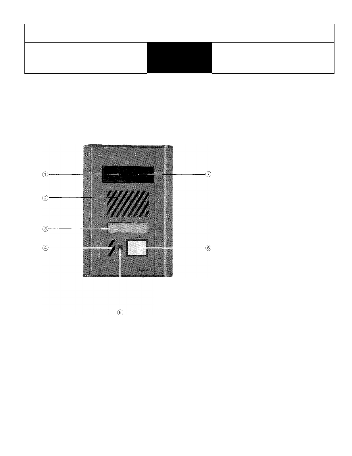
MF-D
(Video door station, semi-flush mount)
J
® CCD camera
@ Speaker
(3) Directory card
(4) Mic.
® Locator LED
@ CALL button
©Infrared LED’s
ACCESSORIES INCLUDED;
n
SCREW(4)
(4mm</> X 35mm)
for mounting to
electrical box
MF-D
FEATURES
MF-D is a video door station for use with IE Chime Tone Intercom Systems: lE-lAD(U), lE-lGD(U) & IE-2AD(U).
Employs CCD (Charge-Coupled Device) camera and infrared LED’s.
Weather-resistant type.
Semi-flush mounts to an electrical box or surface-mounts to MCW-R box.
Camera lens is protected by vandal-resistant shield.
Front panel is of anodized aluminum with tamper-proof screw.
SPECIAL DRIVER
for panel mounting
screw
DIRECTORY
CARDI6)
- 1
Page 2
BEFORE YOU INSTALL AND OPERATE THE EQUIPMENT
- Prohibitions and precautions -
IIMSTALLATIOIM
©DO NOT CONNECT ANY TERMINAL TO AC POWER LINES.
When you mount MF-D in place of existing bell or chime, be sure to disconnect wires from the
present transformer.
@ DO NOT OPEN THE MF-D UNIT, WITHOUT FIRST REMOVING PLUG OF POWER SUPPLY
FROM AC OUTLET.
@ Do not drop or hit the MF-D which may damage the CCD camera unit.
©Avoid running the connecting wires through doors, windows or between
furniture, which may pinch and disconnect the wires.
INSTALLATION LOCATION
NEVER
® Select the MF-D installation location, observing the following con
ditions.
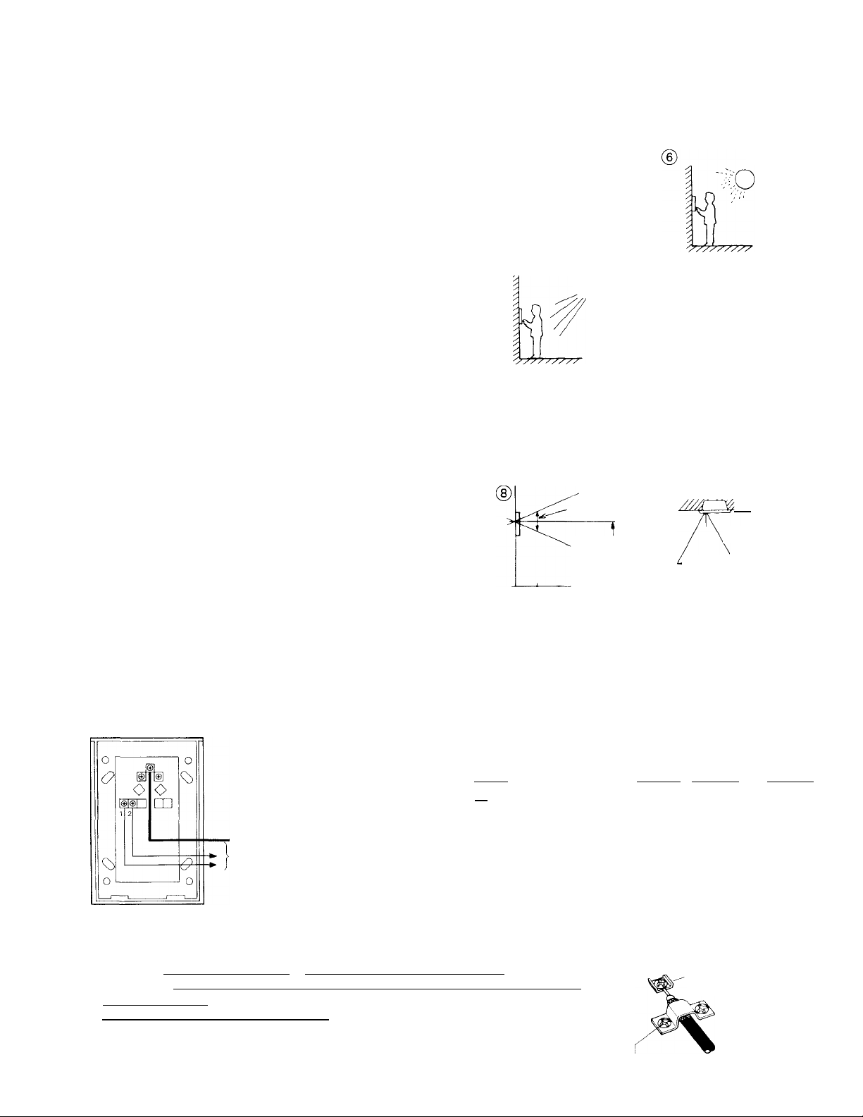
® Avoid installing the MF-D in a location that would be exposed to;
* direct sunlight, * temperature/humidity extremes, * water, * oil,
* dust, * iron dust, * inflammable and chemical products, etc., or
* where the strong light source is behind the person standing at the
door station. The face will apear dark on the room station monitor.
This situation can occur when buildings create shadows on entry
areas.
@ As shown, it is recommended that the MF-D be installed at an en
trance not exposed to direct sunlight and with 200 to 300 lux secured
on the object.
INSTALLATION HEIGHT
@
WEST
NORTH
©NTRANCE
MF-D
SOUTH
©Taking the adults’ average height into consideration, decide a most
suitable height of MF-D door station.
It is suggested that the center of a camera lens be installed
at an adults’ average height minus 10cm(4").
MAINTENANCE
Approx. 500 mm
(19-5/8")
Average adults'
height minus
100 mm (4")
@ Clean your MF-D unit with a soft cloth dampened with neutral house
hold cleanser. Never use lacquer thinner or benzine, etc.
500 mm (19-5/8")
)Do not splash water directly on unit.
STREET
LIGHT
EAST
i
IDIM
BRIGHT
NORTH
ENTRANCE
WEST ^ MF-D EAST
SOUTH
y/////A
Approx. 760 mm (30")
NEVER
NEVER
©
500 mm
(19-5/8")
INSTALLATION
(1) ACUTAL TERMINAL LOCATION
COAXIAL CABLE: Connect to 1, 2, 3 on MFW-P3/P3I
I 1 1 I Connect to either |Pl| |E1|, |D2| |E2| or |P3| |E3|
i 2 j I
’ terminals (on MFW-P3/P3B)(non-polarized).
COAXIAL CABLE |
2 wires
MF-D BACK VIEW
to: MFW-P3/P3B adaptor
1
(2) COAXIAL CABLE CONNECTION
Use 3C-2V or 3C-2V OR RG-59/U which must meet the following specifications;
* [Both core and braided conductors must be of copper (not of copper-weld)|
* Impedance: 75 ohm.
__________________________
* [^rmittcd closed loop DC resistance: 7 ohnu]
* Permitted attenuation: 6 dB at 4 MHz.
* Cable sheath size should not exceed 7.4 mm (5/16").
When using 3C-2V, strip the insulation and fold back the braided conductors, as shown
to avoid shorting to core conductors.
- 2 -
FOLD BACK
11 I
1 1 mm (7/1 6")
3 mm (1/8")
8.5 mm (3/8")
P
Type; 5C-2V Type: 3C-2V
Connect core
conductor to terminal
Connect braided conductors
with clamp
Page 3

(3) WALL MOUNTING
SEMI-FLUSH MOUNTING
(to new and plastered wall);
FRONT PANEL
DIRECTORY CARD
OVAL HEAD SCREW
DRIVER
FASTEN
MAIN UNIT
83.5 3-GANG BOX(w/mud ring)
(3-5/16") (as specified)
RIB
MCW-V DIMENSIONS;
Loosen the oval head screw on bottom front panel by the provided driver.
Pull the front panel at bottom and remove from the main unit.
Connect wires on terminals on back of the main unit.
Mount the main unit on the electrical box with supplied four screws (4 mm 0 x 35 mm).
Attach the front panel to the main unit inserting to the rib provided on top main unit.
Rescrew the special screw on bottom front panel by the provided driver.
GANG BOX REQUIREMENTS;
MF-D can be mounted on the 3-GANG BOX as specified below;
For North America; * 3-GANG BOX, 1-5/8" DEEP, WITH RAISED COVER, NEMA standards
* 3-GANG BOX, SHALLOW, Tile Wall Box 1/2" knockouts, NEMA standards
For everywhere except N. America; * JIS 3-SWITCH BOX (w/mud ring) (Model: DS4913, to be supplied
by AlPHONE).
SEMI-FLUSH MOUNTING (in existing constructions);
To mount MF-D on existing wall or on marble wall (where no plaster is used), use Aiphone’s MCW-V box, without mud ring.
Cut out a hole in the wall, of W:95 mmx H:155 mm (W: 3-3/4" x H:6-l/8"), securing depth of 65 mm (2-9/16").
SURFACE-MOUNTING;
Aiphone supplies MCW-R box, designed for MF-D surface-mounting. For details, refer
to the Instructions packed with MCW-R box.
(4) DIRECTORY CARD REPLACEMENT
The six directory cards are supplied with the MF-D unit. When replacing the card,
first remove front panel and the card cover can be removed, using a screwdriver.
WIRING DIAGRAM
a
IE-2AD(U)/MF-D VIDEO SYSTEM;
Connect power supply PS-24N to MFW-P3/P3B
& IE main room station individually.
MFW-CZ video camera installation is optional
(for surveillance of 3rd entry/area).
3^ When lE-lAD(U) or lE-lGD(U) main room
stations are used, there are no
terminals and only one MF-D video door station
can be connected.
For wiring connections on MFW-P3/P3B, be sure that
door station and door release terminals collate with one
another in the following manner;
Coaxial cable terminals
Door station terminals Dl, El
Door release terminals LI
1 2 3
D2
D2, E2 D3, E3
L2 L3
Door (i)
MF-D
H
EL-9S ®
A1
D3
- 3
Door \2)
MF-D
•11
EL-9S @
[I>
PS-24N
POWER
SUPPLY
MFW-P3
SCREWDRIVER
To; next MFH-U
IE-2AD(U)
MAIN ROOM STATION
To; IEH-1CD
Sub room station
Page 4

OPERATIONS
To call room station;
Momentarily depress CALL button.
SPECIFICATIONS
* Power source:
* Camera unit:
* Minimum illumination:
* Scanning line:
* Object pickup range:
* Calling:
* Wiring:
* Wiring distance:
Coaxial cable
RG-59/U (22GA)
AWG
Distance
* Dimensions and weight:
Communicate handsfree when the room station replies.
Stand in front of the camera at approx. 30 cm (1') distance,
to obtain the best picture at night.
Supplied by MFW-P3/P3B video adaptor.
CCD (Charge-Coupled Device) and infrared LEDs.
1 lux or less on the object at a distance of 30 cm (1') or less.
It is suggested to secure brightness of 200 to 300 lux in the dark area to obtain best picture.
525 lines.
Approx. 50 cm (19-5/8") (average) vertically.
Approx. 76 cm (30") (average) horizontally.
Electronic chime tone.
One coaxial cable plus 2 wires.
Eor audio/video;
RG-59/U (20GA)
22AWG
165'
22AWG
495'
(H X W X D) 175 X 120 x 63.5 (mm) (6-7/8
Coaxial cable
Diameter
3C-2V
0.65 mm
Distance 50 m 150 m
X 4-3/4" X 2-1/2"). Approx. 560 g (1.23 lbs.).
5C-2V
0.65 mm
Projects 25.5 mm (1") from the wall.
K
Si
Aiphone warrants its products to be free from defects of material and workmanship under normal use and service for a period of one
year after delivery to the ultimate user and will repair free of charge or replace at no charge, should it become defective upon which
J5,
examination shall disclose to be defective and under warranty. Aiphone reserves unto itself the sole right to make the final decision
whether there is a defect in materials and/or workmanship; and whether or not the product is within the warranty.
This warranty shall not apply to any Aiphone product which has been subject to misuse, neglect, accident, or to use in violation of
instructions furnished, nor extended to units which have been repaired or altered outside of the factory.
I
This warranty does not cover batteries or damage caused by batteries used in connection with the product,
i This warranty covers bench repairs only, and any repairs must be made at the shop or place designated in writing by Aiphone. Aiphone
^ will not be responsible for any costs incurred involving on site service calls.
WARRANTY
^scpcpcp<^><;pepcpcpcpepcpc^>cp<rgscpcpcpep<^3epepcpcpcpcpcf>cpcpcf<pcpcpcpcpcpepcpcpcpcpcpcf^^
AIPHONE CO., LTD., NAGOYA, JAPAN
AIPHONE CORPORATION, BELLEVUE, WA.
INTERCOM SYSTEMS
® AIPHONE
HOME, BUSINESS, INDUSTRY
MF.D-KEI0390C
- 4 -
Printed in Japan(E)
 Loading...