

Page 1
VIDEO DOOR STATION
MODEL:
V
_________________________
INSTALLATION MANUAL
M C-D
830313 0788
Door station with
CCD camera,
surface-mount
O AlPHONE
T
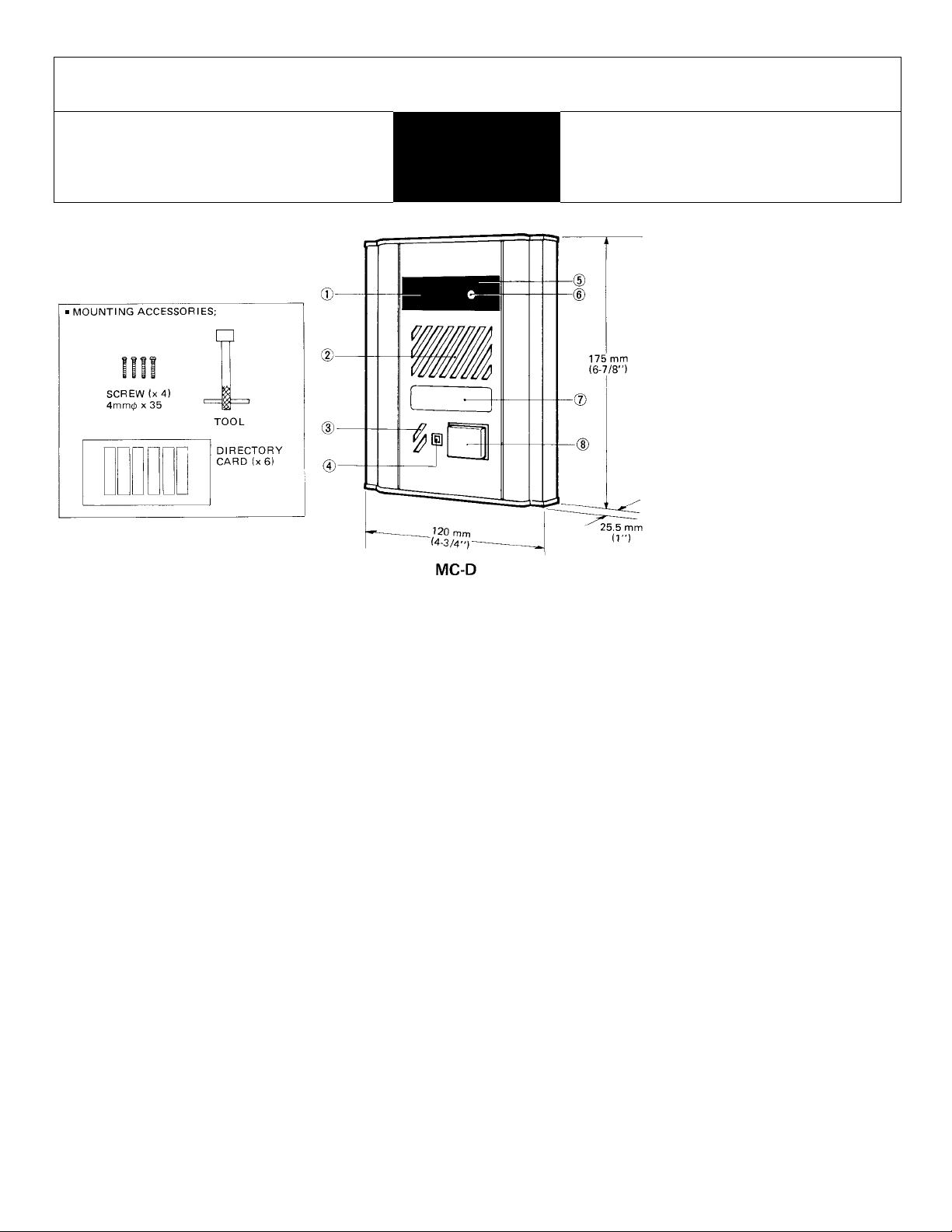
20.5 mm (3/4")
134 mm 92 mm
(5-1/4") (3-5/8”)
20.5 mm
13/4”)
25.5 mm
38 mm
J
a
SIDE VIEW
NAMES AND FUNCTIONS
© CCD camera
@ Speaker
® Microphone
® Location indicator LED (red)
(§) Infrared LEDs
® Camera ON indicator LED (green)
@ Directory card
® CALL button
Terminal section
FEATURES
MC-D is a video door station for use with MC-U/MCH-U video monitor and IC-series Chime Tone Intercom: either IC-1 AD(U),
IC-1GD(U)/A or IC-2AD(U)/Aor TD-H selective call intercom system.
MC-D can be used as a surveillance camera, using MCW-P3, 3-camera adaptor (with video monitoring capability for up to 3
locations). Can be installed max. one MC-D & two surveillance cameras for MCW-P3/IC-1GD(U)/A system, and max. two
MC-D and one surveillance camera for MCW-P3/IC-2AD(U)/A system.
Employs CCD (Charge-coupled device) camera, featuring;
1. almost permanent life of camera unit,
2. no possibility of being damaged by strong light.
3. more compact and lighter weight.
4. low current circuitry.
5. clear picture by higher resolution,
Weather-resistant type.
Camera lens is protected by vandal-resistant shield. Front panel is of anodized aluminum with tamper-proof screw.
The camera has wide-angle lens, capturing image from 25 cm to 5 m (10" to 16')Either semi-flush or surface mounting (MCW-R surface mounting box supplied by AlPHONE).
Simple wiring. One coaxial cable plus single pair.
MAW-B relay box for auxiliary light to illuminate the caller from the front (to improve backlight phenomenon).
6. no after-image created.
7. picture less distorted, as not so affected by magnetic and
electrostatic field.
8. auto-iris sensitivity adjustment.
maintenance-free, as periodical replacement of vidicon has
9.
been eliminated.
- 1 -
Page 2
BEFORE YOU OPERATE AND INSTALL THE EQUIPMENT
— Prohibitions and precautions —
OPERATION;
DO NOT HOLD HOOK SWITCH DOWN WHILE PICKING UP HANDSET. THE CHIME
TONE SOUNDS THRU THE HANDSET RECEIVER ELEMENT AND COULD CAUSE
HEARING DAMAGE.
INSTALLATION;
1. DO NOT CONNECT ANY TERMINAL ON ANY UNIT TO AC POWER LINES. When you mount MC units in place of existing bell or chime, be sure to disconnect wires from the present transformer.
DO NOT OPEN THE MC-D UNIT, WITHOUT FIRST REMOVING PLUG OF PS-24N
POWER SUPPLY FROM AC OUTLET.
Do not drop or apply mechanical shocks which may damage the CCD unit.
Avoid mnning the connecting wires thru doors, windows or between furniture, which
may pinch and disconnect the wires.
INSTALLATION LOCATION REQUIREMENTS
Select the MC-D installation location, observing the following conditions.
Avoid to install MC-D in the locations that would be exposed to direct sunlight, temperature/humidity extremes, water,
1.
oil, dust, iron dust, inflammable and chemical products, etc.
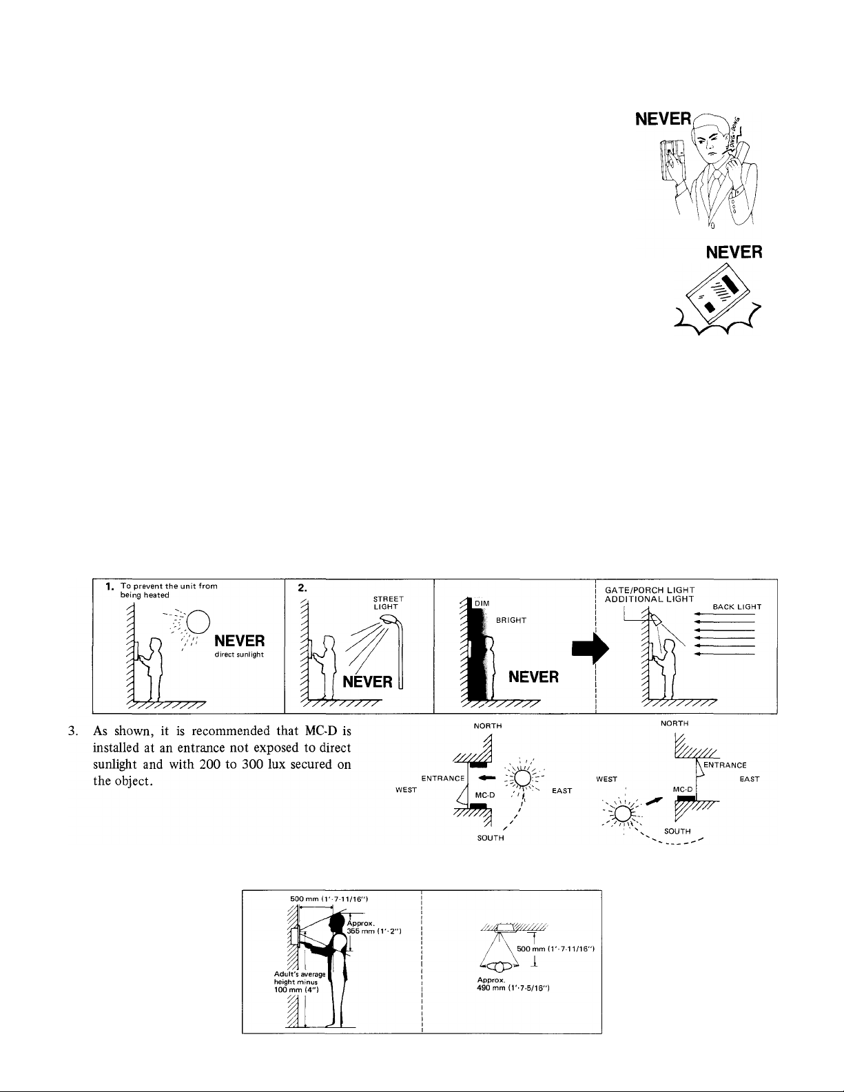
If the strong light source is behind the person standing at the door station and there is not illuminating lamp spotlighting
the face, the face will appear dark on the room station monitors. This situation can occur when buildings create shadows
on entry areas.
If gate/porch light is not provided, a separate illumination light must be installed to prevent the above and/or to illuminate
the caller during night. The AlPHONE Relay Unit MAW-B is available, to turn on the illumination light when the caller
presses call button on the MC-D station.
(For installation information, see the Instructions packed with MAW-B unit).
NOTE: While
MC-D is exposed to direct sunlight or strong light (approx. 30,000 lux), the auto-iris is activated just when
CALL
4. Taking the adults’ average height in consideration, please decide most suitable height of MC-D door station. It is suggested
that the center of a camera lens be installed at an adults’ average height minus 10 cm (4").
MAINTENANCE
1. Clean your MC-D unit with a soft cloth dampened with neutral household cleanser. Never use thinner nor benzine, etc.
- 2 -
Page 3

COAXIAL CABLE REQUIREMENTS
Use 5C-2V or 3C-2V OR RG-59/U which must meet the following specifications;
* Both core and braided conductors must be of copper (not of copper-weldi.
* Impedance: 75 ohm.
* Ll’emiiiied chised loop DC rosislance; 7 uhin.|
* Permitted attenuation: 6 dB at 4 MHz.
* Cable sheath size should not exceed 7.4 mm (5/16")
When using 3C-2V, strip the insulation and fold back the braided conductors, as shown
to avoid shorting to core conductors.
DIRECTORY CARD REPLACEMENT
The six directory cards are supplied with the MC-D unit. When re
placing the card, first remove front panel and the card cover can be
removed, using a screwdriver.
FOLD BACK
11 mm (7/16")
3 mm (1 /8")
8.5 mm (3/8") Vl
Type; 5C-2V Type 3C-2V
Connect braided conductors
with clamp.
- Connect core
conductor to terminal
INSTALLATION
(1) Gang box requirements;
For semi-flush mounting to new and plastered wall;
MC-D can be mounted on the 3-GANG BOX as specified below;
* 3-GANG BOX, 1-5/8" DEEP, with RAISED COVER, NEMA standards.
* 3-GANG BOX, SHALLOW, The WaU Box 1/2" knockouts, NEMA standards (avahable in U.S.A.).
OR
* JIS 3-SWITCH BOX (with cover) (Model: 3SSB, to be supplied by AIPHONE).
For semi-flush mounting (in existing constructions);
To mount MC-D on existing waU or on marble wall (where no plaster is used), use Aiphone’s MCW-V box, without cover.
Cut out a hole in the waU, of W: 95 mm x H: 155 mm (W: 3-3/4" x H: 6-1/8"), securing depth of 65 mm (2-9/16").
For surface mounting;
Aiphone supplies MCW-R box, especially designed for MC-D surface-mounting. For detahs, refer to the Instructions packed
with MCW-R box. :!0:4:T'gANG BOX imith cover)
(2) Semi-flush mounting; main unit (as specified) MCW-V dimensions;
FRONT PANEL
DIRECTORY
CARD
SPECIAL SCREW
lx 1)
1.
Loosen the oval head screw on bottom front panel by the provided tool.
2.
Pull the front panel at bottom and remove from the main unit.
3.
Connect wires on terminals on back of the main unit.
Mount the main unit on the gang box with the supplied four screws (4 mm0 x 35 mm).
4.
5.
Attach the front panel to the main unit inserting to the rib provided on top main unit.
6.
Rescrew the special screw on bottom front panel by the provided tool.
-3 -
Page 4

a
WIRING DIAGRAM
MC-D BACK VIEW
TERMINAL
I For additional light wiring, see the |
i Instructions for MAW-B unit. !
VIDEO DOOR
STATION (with
CCD CAMERA)
for calling &
communication
IC-1 AD(U)
IC-1GD(U)/A
OR IC-2AD(U)/A
POLARIZED
COAXIAL CABLE FROM MC-D MUST
BE CONNECTED TO TERMINAL
ON MC-U.
Run power supply line from PS-24N
to each MC-U and 1C intercom.
IMPEDANCE-MATCHING PLUG
SHOULD"~b'e REMOVED ON VIDEO
MONITORS, EXCEPT ON THE FAR
THEST MCH-U,
IF SYSTEM INCLUDES ONE VIDEO
MONITOR ONLY, THE PLUG SHOULD
REMAIN ATTACHED.
• PLUG ATTACHED: SET TO 75 OHM
• PLUG REMOVED; SET TO HIGH
IMPEDANCE POSITION
POSITION
(^1
* Power source:
* Camera unit:
* Minimum illumination:
SPECIFICATIONS
Supplied by MC-U main video monitor.
CCD (charge-coupled device).
1 lux on the object... at a distance of 30 cm (1') or less.
It is suggested to secure brightness of 200 to 300 lux in the dark area to obtain the best picture.
* Scanning line:
* Resolution:
* Object pickup range:
625/525 lines.
More than 300 TV lines vertically and horizontally.
Approx. 35.5 cm (14") vertically,
Approx. 49 cm (19-5/16") horizontally, both at a distance of 50 cm (19-5/8").
* Calling:
* Wiring:
2- or 4-stroke electronic chime.
One coaxial cable plus single pair of wires.
* Wiring distance:
For audio/video;
3C-2V,0.65mm dia. 5C-2V, 0.65 mm dia.
50 m
RG-59/U (22 GA), 22 AWG
165'
RG-59/U (20 GA), 22 AWG
150 m
490'
MC-D dimensions:
Coaxial cable; Wire gauge
Distance between MC-D and MC-U
Coaxial cable; Wire gauge
Distance between MC-D and MC-U
H:175mm x W:120 mm x D:25.5mm (recessed: 38mm)
H:6-7/8" X W:4-3/4" xD:l" (recessed: 1-1/2").
Weight:
3«
Aiphone warrants its products to be free from defects of material and workmanship under normal use and service for a period of one
%
year after delivery to the ultimate user and will repair free of charge or replace at no charge, should It become defective upon which
1,
examination shall disclose to be defective and under warranty. Aiphone reserves unto itself the sole right to make the final decision
whether there is a defect in materials and/or workmanship; and whether or not the product is within the warranty.
This warranty shall not apply to any Aiphone product which has been subject to misuse, neglect, accident, or to use in violation of
instructions furnished, nor extended to units which have been repaired or altered outside of the factory.
This warranty does not cover batteries or damage caused by batteries used in connection with the product.
This warranty covers bench repairs only, and any repairs must be made at the shop or place designated in writing by Aiphone, Aiphone
will not be responsible for any costs incurred involving on site service calls.
Aiphone Co., Ltd., Nagoya, Japan INTERCOM SYSTEMS
Aiphone Corporation, Bellevue, Washington
MC-D-IM (E) 0788G
Approx. 680 g (1.5 lbs).
WARRANTY
cpepepe|5cpc|xpepc|5e5xpepepe|5epep<pe|xpe|xpepepe|xjse|5epcpepepepepepip<pep<pe|xpepe5xpejse|xpepi|5ey>
@
-4-
ll\l I bKLtUM :sY&l ttvi:>
AIPHONE
HOME, BUSINESS, INDUSTRY
Printed in Japan (E)
 Loading...