

Page 1
@ AIPHONE
834324 MA-DI-0286©
VIDEO INTERCOM SYSTEM
MODEL: MA-D(i/oor station with illumination lamp)
- INSTRUCTIONS -
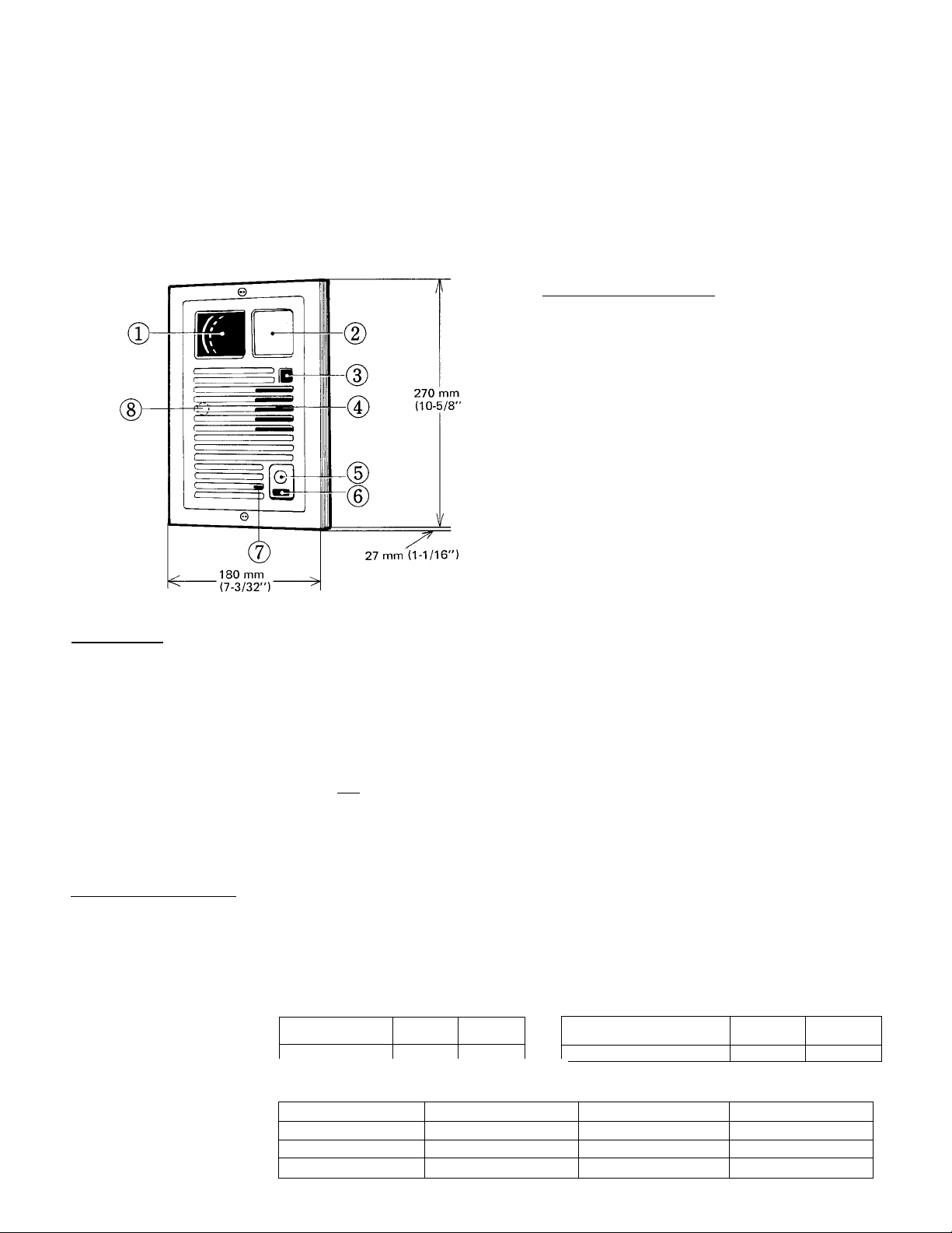
(names and functions)
(T) Camera
Illumination lamp
Beam sensor (to protect vidicon in the camera)
Speaker
Call button
(^LED
(7) Microphone
Vertical picture angle adjuster
C features)
* Thin, compact design. Projects only 27 mm (1-1/16”) from the wall.
* Vandal-proof door station. Camera lens is protected by high impact-resistant shield. Door station panel is heavy-duty
aluminum with tamper proof screws.
* Sharp camera focus. Door station camera has wide-angle lens, capturing image from 25 cm to up to 5 m (10” to 16’).
* Beam sensor protects the camera from potential damage due to excessive light.
* Quick response door station. Illuminating lamp is lit upon pushing call button. Room station video monitor didplays image
of caller immediately after call tone sounds.
* Monitor button allows you to both see and hear outside.
* Either semi-flush or surface mounting.
* Simple wiring. One coaxial cable plus one pair for illumination lamp.
* Vertical picture angle adjuster included on door station.
* MAW-B relay box for addtional light to illuminate the caller from the front.
C SPECIFICATIONS )
* Vidicon: 2/3 inch vidicon (2.25 inch through lens)
* Illumination requirements: About 10 lux.
Carrier frequency:
Wiring:
Wiring distance:
Transmission
Reception
...............
.....................
6.0 MHz.
6.5 MHz.
One coaxial cable plus a pair wires for illumination lamp.
Audio/Video;
Coaxial cable
Max. distance 100 m 300 m
*Coxial cable requirements on page 3 must be met.
3C-2V 5C-2V
Coaxial cable
(size of core conductor)
Max. distance
Illumination lamp;
Wire gauge 0.8 mm dia.
Max. distance 100 m
Wire gauge
Max. distance
20 AWG 16 AWG
330’
1.2 mm dia.
200 m
660’
RG-59/U
(22GA)
600' 1,000'
RG-59/U
1.6 mm dia.
300 m
14 AWG
1,000’
(20GA)
1 -
Page 2
(components available for use with your video intercom SYSTE]^
m MA-D, Door station with camera, EL-9S, Electric door release.
: J illumination lamp & beam sensor.
MA-1 A, Room station with video
IBR-1, Extension chime call speaker.
monitor and door release button.
MAW-J; Flush mounting back box for
PS-24N, Power supply adaptor,
MA-D and MA-1 A.
DC-24V, 2A.
MAW-B, Relay box to illuminate
additional lamp. Powered by
MAW-R. Surface mounting box for
MA-D.
PS-24M power supply.
(installation)
Do not attempt to install your intercom system until you have read and thoroughly understood the installation procedure
Aiphone’s warranty is void if system is installed in a manner other than described in this manual.
( ACTUAL TERMINAL LOCATION^
MA-D
[Y] ^ ; For illumination light. Connect to [z] , |~Z~|
terminals on MA-1 A room station (non-polarized).
Connection for
coaxial cable
from MA-1 A
room station.
CABLE CLAMP
■11
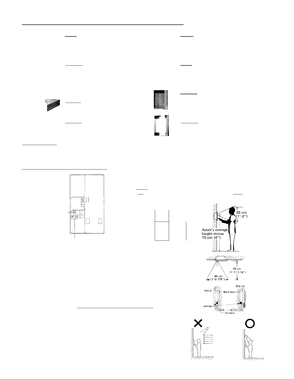
(installation location requirements)
* The location of the door station should not be exposed to:
- direct sunlight
~ a strong light source such as mercury street lamps, porch or gate lights,
which may create the spotted stain (permanent burn-out) in the picture
tube of master station.
— direct rain or snow.
* Please decide most suitable height of MA-D door station, taking the adults’
average height in consideration. It is suggested that the center of a camera
lens come at a height of adults’ average height minus 10 cm (4’).
* If the sunlight or other strong light source is behind the person standing at
the door station, and there is not illuminating lamp spotlighting the face, the
face will appear dark on the room station monitor. This situation can occur
when buildings create shadows on entry areas.
A separate illumination hght may be necessary. The Aiphone Relay Unit
MAW-B is available, to turn on an external light when the visitor depresses
the call button on the door station.
* When using conduit for running cable, please put sponge or the like at both
ends to avoid acoustic feedback through the conduit.
- 2
Page 3

(flush mounting to wall)
1. Use a template provided to open a hole of H: 274 mm x W; 202 mm (H; 10-3/4” x W; 7-15/16”), securing depth of 58 mm
(2-5/16”) or deeper.
2. Install MAW-J back box into the wall.
3. Attach the bracket to the back box with 4 screws so as to be fitted vertically.
4. Attach MA-D body to the bracket with 4 screws.
5. Remove a black paper put on the camera lens.
6. Attach front panel to the MA-D body with 2 special tamper proof screws (driver is included).
BACK BOX MAW-J
' 274 mm
■ (10-3/4")
SPECIAL SCREW X 2
FRONT PANEL
MA-D BODY
MOUNTING BRACKET
(included in MAW-J)
SCREW X 4
(46 X 35 mm)
included in MAW-J
* BLACK PAPER to protect vidicon from damage by strong
light. Must be removed before attaching front panel.
NOTE: When mounting MA-D on the surface of gate or wall, please use MAW-R surface-mounting box.
(coaxial cable connection)
• COAXIAL CABLE REQUIREMENTS:
Use 5C-2V or 3C-2V OR RG-59/U which must meet the following
specifications;
* Both core and braided conductors must be of copper.
* Impedance: 75 ohm.
* Permitted closed loop DC resistance: 14 ohm.
* Permitted attenuation: 6dB at 4MHz.
* Cable sheath size should not exceed 7.4mm (5/16”).
• When using 3C-2V, strip the insulation and fold back the braided
conductors, as shown to avoid shorting to core conductor.
Type: 5C-2V
16.5 mm (5/8”)
— 3 mm
— (1/8")
8.5 mm (3/8")
Type: 3C-2V
Connect core conductor
to terminal.
(2-9/32")
Connect braided conductors with clamp.
Page 4

(wiring diagram)
DOOR STATION
MA-D
ROOM STATION
MA-1A
CCONNECTING MAW-B RELAY BO)Q
When door station must be installed in a place where a caller is strongly backlighted, an additional light must be installed in
conjunction with MAW-B relay box to illuminate caller from the front.
Connect white and blue leads of MAW-B to |b1 E terminals of MA-IA by wire nuts. Connect orange wires of MAW-B
to the light switch. Connecting reversely will cause permanent damage to MAW-B relay box.
* Specifications;
Power source: DC-24V. Extended from PS-24N power supply.
Relay contact capacity: Less than lOOW.
Wiring: 2-wires (polarized) between MAW-B and MA-1A room station.
2-wires (polarized) between MAW-B and PS-24N power supply.
Wiring distance: Up to 80 m (26’) with 0.65 mm dia. (22 AWG) wires between MAW-B and PS-24N.
(adjusting vertical picture angle)
The MA-D unit includes an adjuster for vertical picture angle to move a camera lens
by 2.5 cm (1”) each upward and downward.
1. Remove the front panel.
2. Remove the cap.
3. Adjust using a minus head screw driver.
4. Replace the cap for weather resistance.
(replacement of an illumination LA!^
1. Remove a front panel, using a special driver provided.
2. Remove 4 screw and lamp cover.
3. Attach the tube provided to lamp and pull it off.
-4
Page 5

( OPERATIONS )
• CALLING FROM DOOR STATION
o
Momentarily depress CALL button^J
* 4-stroke electronic chime sounds at MA-
lA room station, and you hear call-
acknowledged tone.
*
ANSWERING AT ROOM
STATION
Pick up the handset and talk.
* After 4-stroke chime sounds, picture
appears. Pick up the handset and talk to
the person in the picture.
* Timer circuit shuts off the picture and
voice communication automatically ap
proximately one minute after you pick up
the handset to answer. You can turn on
the circuit again by depressing the monitor
button.
* If you do not answer when you are called,
the picture goes off approximately 20
seconds after the chime is heard.
Note: When the door station would be exposed to direct sunlight or other strong light of
more than 20,000 lux, the beam sensor works to close the shutter and the picture
will not appear on the video monitor of room station, but calling and communication
can be made.
Illumination lamp comes on
automatically.
RELEASING DOOR LOCK
Depress and hold down electric
door release button.
* While the door release button is held
down, the door release will remain open,
and a buzzing sound is heard at the door.
* When the door release button is released,
the door is locked again.
6
/Talk handsfree standing in front'
of the camera lens, when master
.replies.
• MONITORING THE DOOR
STATION
Momentarily depress
MONITOR button.
* Picture and sound come ON by depressing
the monitor button. You can watch and
listen to the outside without picking up
the handset.
* In the monitoring mode, the master
station cannot be heard at the door
station, and you may pick up handset for
talking to door station, if necessary.
* Master station can receive a call from the
door station while monitoring.
*When you need to stop monitoring, pick
up the handset once and hang up.
* Approximately one minute after the
monitor button is depressed, the master
station turns back to standby mode auto
matically.
CAUTIONS )
* DO NOT OPEN THE BACK COVER OF THE MA-D UNIT, WITHOUT FIRST REMOVING PLUG OF PS-24N POWER
SUPPLY FROM AC OUTLET.
The high voltage is loaded on the camera unit.
* DO NOT CONNECT ANY TERMINAL ON MA-D UNIT TO AC POWER LINES.
* Handle the MA-D unit with utmost care. The built-in camera-tube, if dropped or struck, can be damaged.
Do not run the coaxial cable through doors or windows or between furniture. Windows, doors or furniture may pinch
coaxial cable.
5 -
Page 6

(TROUBLE-SHOOTING GUIDE)
No. MODE OF TROUBLE
Unit totally dead.
1
Only picture tube lights.
2
Picture tube lights, but no picture.
3
Can call and communicate, but picture tube
4
remains dark.
5 Cannot call from door station.
6 Picture is okay, but no audio signal.
7 Inferior sensitivity and contrast of picture tube.
8 Fuzziness in bright area.
Spots in picture.
9
“Negative” image (reversal of black and white).
10
LOOK FOR
* Power supply not plugged.
* Connector leads to power supply disconnected.
* Short in connector leads to power supply.
* Inferior connector of coaxial cable at the terminal end.
* Short in coaxial cable connections at the terminal end.
* Break in coaxial cable.
* Coaxial cable disconnected.
* Defective door station (in camera).
* The shutter has closed to protect the vidicon in the camera
from direct sunlight . . . this is normal operation, not a fault.
* Defective door station (in camera).
* Defective room station (in video monitor).
* Defective door or room station.
* Defective door or room station.
* Worn-out vidicon (A general life of vidicon is approximately
3 years in normal application).
* Worn-out picture tube (A general life of picture tube is
approximately 4 years in normal application).
(cleaning your intercom stations)
* Your Aiphone intercom stations may be cleaned with a soft cloth dampened with household cleanser, such Mr. Clean or
Fantastik.
We at AIPHONE are proud of our products. Our designers and engineers strive to bring you the finest in communication
equipment. Each item has been carefully tested and inspected before leaving our factory. Properly installed and used, your
Aiphone intercom system should give years of trouble-free service.
We are pleased to offer the following warranty:
WARRANTY
Aiphone warrants its products to be free from defects of material and workmanship under normal
use and service for a period of one year after delivery to the ultimate user and will repair free of
charge or replace at no charge, should it become defective upon which examination shall disclose
to be defective and under warranty. Aiphone reserves unto itself the sole right to make the final
decision whether there is a defect in materials and/or workmanship; and whether or not the prod
uct is within the warranty.
This warranty shall not apply to any Aiphone product which has been subject to misuse, neglect,
accident, or to use in violation of instructions furnished, nor extended to units which have been
repaired or altered outside of the factory.
This warranty does not cover batteries or damage caused by batteries used in connection with the
product.
This warranty covers bench repairs only, and any repairs must be made at the shop or place des
ignated in writing by Aiphone. Aiphone will not be responsible for any costs incurred involving on
site service calls.
US*'
I W M* W t
m
i. ■”’•******* i,
Aiphone Co., Ltd., Nagoya, Japan
Aiphone Corporation, Bellevue, Washington
MA-DI-0286©
— 6
O
INTERCOM SYSTEMS
AIPHONE
HOME, BUSINESS, INDUSTRY
Printed in Japan (E)
 Loading...