

Page 1
#90111 0207
Single Master Station with Door Release
- REFER TO INSTALLATION MANUAL INSIDE LEM-1DL BOX FOR STANDARD
INSTALLATION INFORMATION -
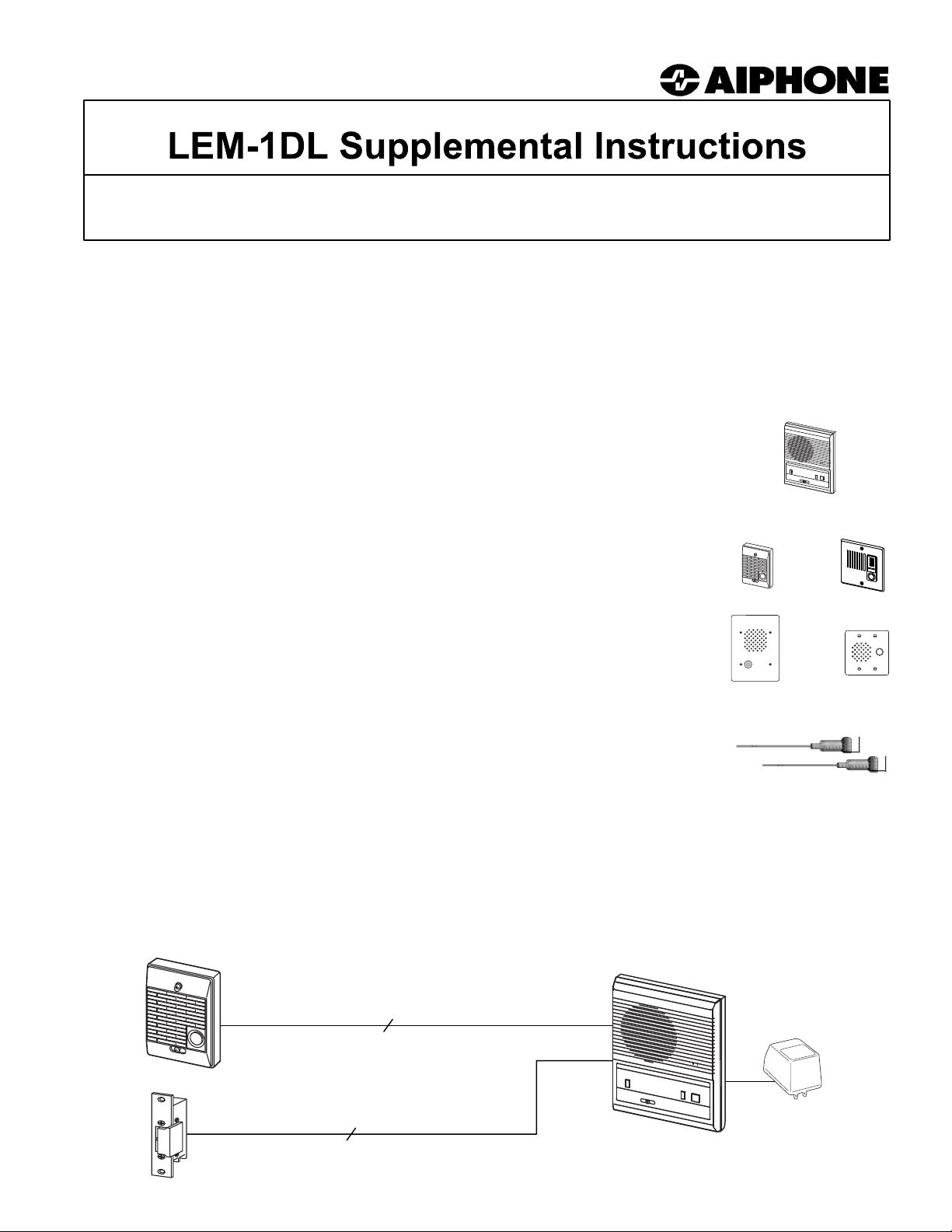
The LEM-1DL master station provides communication to and from a door station, and has a separate
ton for door release. This supplemental instruction manual addresses many of the additional functions
but
and
modifications for the LEM-1DL system, including installation and troubleshooting information.
MASTER STATION:
LEM-1DL: 1-call master station with "Normally Open" door release button
DOOR STATIONS: (Note: Door stations are weather resistant, made for outdoor use)
LE-D: Surface mount, plastic door station (included with LEM-1DLS)
LE-DA: Flush mount in 2-gang box, stainless steel cover
LS-NVP/C: Vandal resistant flush mount in 3-gang box, white powder-coat finish
LE-SS: Vandal resistant flush mount sub in 2-gang box, stainless steel
LE-SSR: Vandal resistant, red mushroom button, flush mount in 2-gang box, stainless steel
LE-SS-1G: Vandal resistant flush mount sub in 1-gang box, stainless steel
LEM-1DL
OPTIONAL COMPONENTS & ACCESSORIES:
RY-AC/A: External signaling relay (Requires 12VDC power supply)
DAK-2S: Dual master adaptor kit
(1 per 2 master stations. Use 2 DAK-2S for up to 4 total master stations)
SBX-NVP: Surface mount box for LS-NVP/B
SBX-2G: Surface mount box for LE-SS, LE-SSR, LE-DA
SBX-1G-SS: Surface mount box for LE-SS-1G
EL-9S: Door strike (for interior wood frame doors only)
PT-1210N: AC 12V Transformer (used for door strike and for each master station)
PS-1225UL: 12V DC Power Supply, 2.5A, UL Listed
822202: 2 conductor, 22AWG, Shielded wire
(Available in 500' and 1000' boxes)
Install two separate runs of this cable, one for the intercom and one for the door
release.
DOOR RELEA
SE WIRES MUST BE IN A SEPARATELY JACKETED CABLE FROM THE INTERCOM WIRING.
LEM-1DLS Set contains:
1 LEM-1DL, 1 LE-D, 1 PT-1210N.
Door
strike not included.
2 cond. shielded for intercom
LE-D
LS-NVP/
(2
C
DAK-2S
component modules per kit)
LE-
LE-SS
DA
LEM-1DL
LE-D
Separate 2 conductor for door strike
EL-9S, not included with the LEM-1DLS set.
PT-
1210N
LEM-1DL Supplement
Pg.
1
Page 2
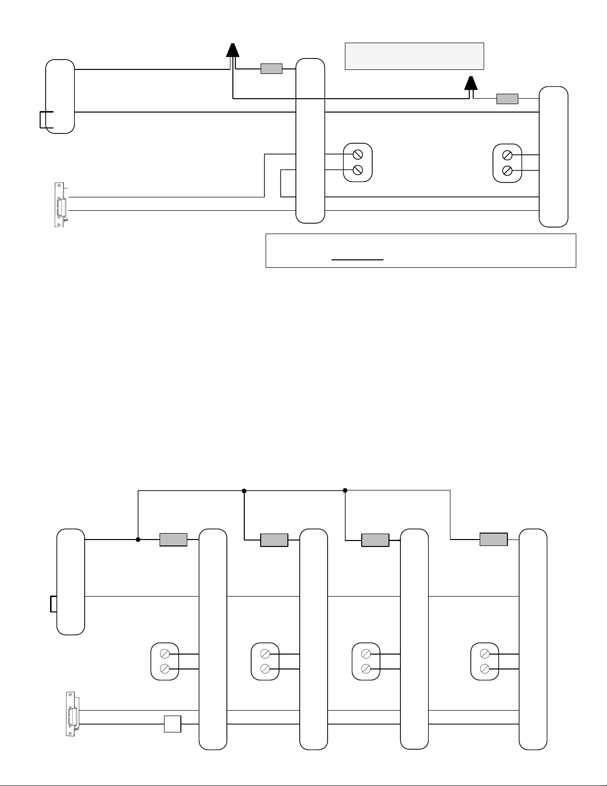
WIRING DIAGRAM: Dual Master LEM-1DL System with DAK-2S Dual Master Adaptor
LE-D
1
Component
Module*
LEM-1DL
1
Please read and understand all
instructions before installation.
Component
Module*
LEM-1DL
1
E
-
Leave E/jumper
attached
E
PT-1210N
PT-1210N
+
Door Strike
Electric strike shown is being powered from
same transformer powering the first LEM-1DL.
-
EL
EL
IMPORTANT!!!
Each master REQUIRES
OPERATION NOTES:
1. Only one master can be used at a time.
2. If both masters are activated, a feedback (squeal) will be heard through the system when either TALK button is pressed.
3. If feedback occurs, press the OFF button on one of the LEM-1DL masters.
INSTALLATION GUIDELINES:
1. Use 2 conductor shielded wire from the door station to the first master, then to the second master.
2. Install the units at the desired locations.
3. Separate PT-1210N power supplies are required for each master station.
4. Install the bare wire leg of the component module directly onto the "1" terminal of the LEM-1DL's.
5. Attach the wire coming form the "1" terminal of the LE-D to the colored wire end of the component modules at both masters. (The component modules
will easily fit within the space available.)
6. Connect the "E" terminals between the door station and master stations.
7. If door release is included, use a separate 2-conductor wire from the "EL" terminals of the masters through an AC transformer and to the door strike.
8. The EL-9S is designed for a standard wood framed door, and for light and medium usage. If a different type of door is used, install a strike appropriate
for the door.
9. The door release button on the master station is a "Normally Open" contact closure.
an individual power supply.
E
+
-
EL
EL
4 LEM-1DL Master Stations with 1 Door
LE-D
1
Component
Module*
E
LEM-1DL
1
E
-
+
-
Door Strike
EL
o
LEM-1DL Supplement
Pg. 2
o
Power Source
for door strike
EL
Component
Module*
LEM-1DL
1
E
+
-
EL
EL
NOTE: In a multi-master system, all masters only talk to the
door station, and only one master can be on at a time.
LEM-1DL
1
E
Component
Module*
LEM-1DL
1
Component
Module*
E
PT-1210N PT-1210NPT-1210NPT-1210N
+
-
EL
EL
+
-
EL
EL
Page 3

WIRING DIAGRAM: LEM-1DL System with External Signaling using RY-AC Relay
LE Series
Sub
Leave jumper
between E and -
attached
1
E
-
Normally Open Dry
Contact to door
strike and power
Component
Module
NOTE: Intercom must
be powered with 12V
DC power supply
when RY-AC is
connected.
*
LEM-1DL
1
E
+
-
EL
EL
Output of RY-AC (Yellow
wires) provide a momentary
dry contact closure while
the call button on the door
station is being pressed.
PS-1225UL
+
-
WHITE
RED
BLACK
YELLOW
RY-AC
YELLOW
Power source
for bell
BELL
Component Module*
If a DAK-2S is not available, install components as shown below.
Capacitor: 25V, 15-33mfd Non-polarized
Diode: 1N 4148
To 1 of LE-D and
WHITE wire of RY-AC
To 1 of LEM-1DL
SYSTEM CONFIGURATION:
LEM-1DL with Door Release contact activating a Normally Closed relay for a Magentic Lock
Note: For applications requiring a Normally Closed (N/C) contact (Magnetic locks, etc.), an external
relay should be chosen based on the lock’s power source.
When using a 12-18V DC magnetic lock, Aiphone’s RY-18L relay may be used.
For 24V DC magnetic locks, Aiphone’s RY-24L relay may be used.
A 3rd party relay of similar specifications may also be used. Refer to manufacturer’s
documentation for connection details.
LE Series Sub
1
E
-
Leave jumper
between E and -
attached
LOCK
POWER
+
-
RY-18L / RY-24L
LEM-1DL
1
E
+
-
EL
EL
PT-1210N
~
~
Magnetic Lock
COM
N/C
Use Brown & Yellow wires
when connecting to Maglock.
Brn
Org
Yel
Red
Blk
MAGNETIC LOCK WIRING METHOD:
(Normally Closed contact)
Lock Power: Power source for Magnetic Lock
When using 12-18V DC, use the RY-18L.
When using 24-36V DC, use the RY-24L.
LEM-1DL Supplement
Pg. 3
Page 4

INSTALLATION TIPS:
1. Use shielded wire for the communication path, and ground one end of the shield to an earth ground.
2. Run intercom wire at least 20" away from AC wiring, fluorescent lights or dimmer switches.
3. Keep intercom cable away from alarm, data, phone, and video cables.
4. Door release wires must be in a separately jacketed cable from the intercom wires. Use two separate
cables; one for audio and one for door release.
5. When installing a second master station, wire must be run from the first master station, not from the
door station. See diagram on page 2.
6. Do not install master station near light switches, dimmer switches, or other devices that may cause
interference with the intercom system.
7. Do not install the master station on the opposite wall from the door station. If the units are too close,
acoustical feedback may result.
TROUBLESHOOTING GUIDE:
PROBLEM POSSIBLE CAUSE SOLUTION
(A) Press OFF button on master. If call tone still doesn't come through,
read solution (B).
No call tone from door to master station.
No communication from door station. E/- jumper not attached
No call tone, no communication. Chirping sound
when volume control is turned all the way up. Wrong voltage on LEM-1DL.
In a system with RY-AC and external signaling
device connected, the external device is activated
every time the TALK button is pressed.
In a dual master system, call tone is heard at the
second master when pushing the talk switch on one
master. Missing DAK-2S dual master adaptor kit
In a dual master system, feedback occurs when
pressing the talk button. One power supply is used for both masters.
AC noise when listening to the door station. Intercom wiring run close to AC wiring.
AC noise when talking to the door station. Power wires run with communication wires
(A) OFF button on master not pressed.
(B) E/- jumper not attached
DAK-2S component module missing or
installed incorrectly.
(B) Make sure jumper is attached to E/- terminals on door station (or
proper wires jumpered on LS-NVP, LE-SS subs). Wire from E/- should be
connected to E of master.
Ensure that the jumper at the door station is attached between E and terminals.
Check power supply. If it's model SKK-620, remove and replace with
model PT-1210N. Verify that voltage on +/- terminals of LEM-1DL is
between 12-16V AC or 12-24V DC.
Make sure the component module is installed with the bare wire under
the 1 terminal, and the WHITE wire of the RY-AC spliced to the colored
wire.
Install 1 component module from DAK-2S at each master. See
instructions on Pg. 3. If DAK-2S is not available, connect specified diode
and capacitor in parallel and install as shown on Pg. 3.
Ensure that each master has its own power supply. Use any power
supply with output between 12-16V AC or 12-24V DC. Aiphone
recommends the PT-1210N.
Ensure that the intercom wire is run at least 20" away from any AC
electrical wire, or crossed at 90 degrees. Intercom wire should be
shielded, with the drain wire connected to an earth ground at the master
end.
Ensure that power wires coming from the PT-1210N are not run in the
same jacketed cable with the communication wires run to the door.
Aiphone Communication Systems
1700 130th Ave. N.E.
Bellevue, WA 98005
(425) 455-0510
FAX (425) 455-0071
Toll Free Technical Support:
(800) 692-0200
FAX: (800) 832-3765
E-mail [email protected]
Pg. 4
LEM-1DL Supp Instr.
# 90111
0207JDJS
 Loading...