

Page 1
83492000 0836® 0501 US
LEF Series
Open Voice Selective Call Intercom
Models: LEF-3
LEF-5
G AIPHONE
LEF-10
LEF-10S
* LEF-5W, LEF-1OW & LEF-1OSW:
w/Terminal Box prewired
INSTALLATION & OPERATION MANUAL
I
SYSTEM OUTLINE & COMPONENTS-----------------------------------------------------------
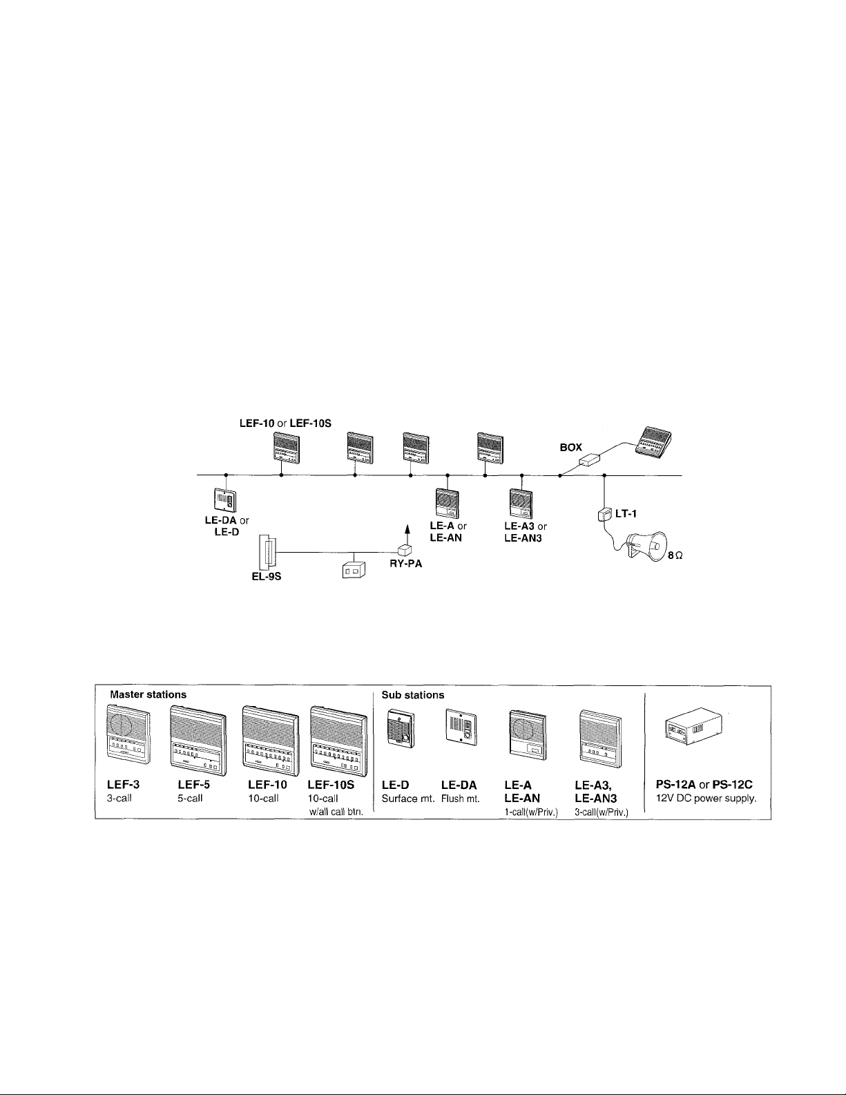
■ System outline
LEF is a flexible Open Voice Selective Call Intercom system, which integrates any combination of master and sub
stations. Selective calling from any master, with handsfree reply. Incorporates a variety of additional features as
described below.
Intercom
masters
Audio door
or room subs
LEF-3, LEF-5
PT-1210N
Package contents
Components available
Intercoms: Masters or subs, intermixable
Sub stations:
LE-DL: Surface-mount w/anodized aluminum
panel
★ 80 horn speaker w/LT-1 matching
transformer
All Call & music:
BG-10C: All call, chime & music adaptor.
Requires a PS-12F power supply (12V DC, 2.5A).
• LEF intercom (LEF-3, 5,10 or 10S)
• Packet of screws
• Installaiton & Operation Manual
PanTilt door stations:
MYW-P1L or IVIYW-P3L adaptor: For 1 or 3 PanTilt doors.
Includes one or two MYH-CU monitors. Max. 3 monitors with
add'l PS-18C or PS-18D.
MY-DC/A, MY-DG/A w/full PanTilt capability.
MY-CA, MY-FA, with prism lens for PanTilt.
MY-DS, wide angle and longer
distance.
MYW-CA overhead enclosure
w/MY-CA installed, with lE/IF
audio door for communication.
1 -
MY-DC/A IWYW-P1L MYH-CU MYH-CU
Page 2
: NAMES & FEATURES
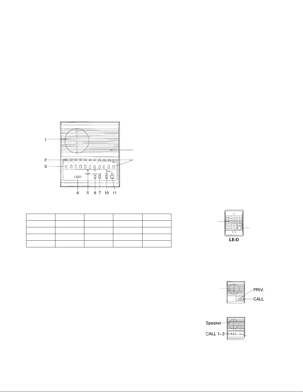
■ Names & functions LEF-3
1
LEF-5,10, 10S
-ODD □-
4 5
Speaker
Call-in LED (3)
Station-Select button (3)
Voice volume control
OFF button (w/ON LED)
Mic.
Occupied LED (In-use)
Priv. button & LED indicator
Talk (listen) button
1
Speaker
2
Call-in LED (5 or 10)
Station-Select button (5 or 10)
3
4
Voice volume control
Occupied (In-use) LED
5
All Call transmit button & LED
6
Door Strike button
7
Mic. (initiator only)
8
9
OFF button (w/ON LED)
10
Priv. button & LED indicator
Talk (listen) button
11
★ LEF-5: 5 station buttons and OFF.
LEF-10: All Call button & LED not included
I Features
Four LEF master stations, intermixable.
Models Capacity
LEF-3 4 stations
LEF-5 6 stations X
LEF-10 11 stations X
LEF-10S
Loop-wired system with muiticonductor shieided cabie.
Aii-master system: 5 common wires ■+ total No. of stations in the system.
If All Call is included: Add 3 additional common wires (PI ~P3).
If Door Release is included (LEF-5/10/10S): Add 1 common (L) -r 1 individual wire
for each door to be released (K# terminals).
Single-master system: 2 wires homerun from each sub to the master.
Leave jumpers between E & - installed.
Intermixed system with masters and subs: 3 wires from each sub to the nearest
master, or 2 common + 1 individual wire per station on a loop. Remove jumpers
between E & - from all stations in a multi-master system.
Optional features:
* 1 or 3 PanTilt doors (w/ MYW-P1L or MYW-P3L
adaptor)
* All Call, chime & Music distribution (w/BG-IOC
adaptor)
* Door strike EL-9S (w/RY-PA relay)
* 80. horn speaker (w/LT-1 transformer)
* External signalling when door/sub calls (w/RY-AC/A
and external device)
11 stations X X
Door strike
All Call transmit PanTilt door
X
X
X
Speaker-
Directory -
LE-DL
-CALL
Speaker
Speaker-
Speaker
-CALL
1
-CALL
LE-DA
LE-A, 1-call
LE-AN, W./PRIV.
PRIV.
LE-A3, 3-call
LE-AN3, w/PRIV.
Page 3

PRECAUTIONS ON INSTALLATION & WIRING
A CAUTION
★ Do not connect AC wires to any terminal on any unit, as fire or unit damage may occur. Connect only the specified
power source on +, - terminals.
★ Do not install more than one power supply (PS-12C or PS-12F or PS-12A) for an entire LEF system.
★ Do not attempt to install or connect wires on LEF equipment while system’s power supply is plugged in.
★ LEF masters and related equipment, except door station, are designed for indoor use only. Do not install outdoors.
IMPORTANT
★ There is no need to disassemble the equipment for installation, other than to open the unit to connect the wires to the
back case. Do not access the PC board or components unless properly qualified.
★ Any other manufacturer’s products installed with this system (power supply, external signalling device, etc.) are not
covered under Aiphone’s warranty.
★ Do not mount LEF equipment in the following places, as it may cause the system to malfunction:
• Fligh or extreme cold temperature areas: under direct sunlight, near equipment that varies in temperature, in front of
air conditioner, inside a refrigerated area, etc.
• Places subject to moisture or humidity extremes.
• Places subject to environmental conditions, such as dust, oil, chemicals, salt, etc.
★ LEF units are electronic devices, which must not be subjected to water or any other liquid.
★ Severe weather conditions, such as lightning storms, may cause damage to LEF equipment.
We recommend that power surge protection be installed as follows: (Flowever, this does not guarantee that no
damage will occur).
• If the power supply has a GROUND terminal, take it to an earth ground. In this case, a separate surge arrester is
not necessary.
• When using a power supply that has no GROUND terminal, install a surge arrester near the output as shown.
• Additional SA-1 surge arresters can be installed to protect communication lines. One SA-1 per 2 wires on master
station.
PS-12A or
PS-12C
_ Surge-
I
Install a surge-arrester
(discharging voltage: 100-180V)
at a point close to the output,
taken to earth ground.
Before actually installing the LEF system, the contents on pages 4-8 must be thoroughly read and understood.
Grounded
LEF model
1
1_1
arrester
(Aiphone model SA-1)
DC 12V
3-
Page 4
WIRING
------------
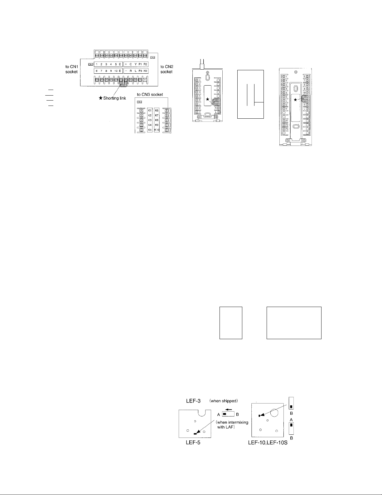
LEF-3 LEF-5, 10, 10S
im
c©
1©
2©
3©
B©
Y©
O
' LEW-5, LEW-10, and LEW-1 OS Terminal boxes are not equipped with K1
~ K5, K1 ~ K10 terminals.
(5)
0
@1
©3
©4
I© 5
F
|©c
|I0V ^ L0||
s©
8®
9©
10®
W\
LEF-10S
Front case
back view
Terminal definitions
LEW-5
Red Yellow Yellow
LEW-10
' Shorting link on E and - terminal: Must remain attached in
Speaker
1 ~ 10:
Station number, establishes communication to other LEF masters (to “C”
a single-master system. Remove when 2 or more masters
are in a system.
terminal) or LE subs (to “1” terminai)
E:
C:
Common communication line
“CALL”, Call receive from another master (and All Call/Chime/Music
reception)
R:
Activates occupied LED to indicate when any master is ON (line drops to
OV DC when any master is on.)
Y:
L:
+j
PI:
Occupied mode control during All Call (becomes -f9V DC during All Call)
Door strike activation (becomes -f12V DC when “key” button is pressed)
12V DC power supply connection
All Call control (becomes -fIOV DC when All Call button is pressed and
activates pretone)
P2, P3:
★ K1 ~ K5 (LEF-5), K1 ~ K10 (LEF10,10S): Selective control terminal, used for video control with
MY PanTilt series, or for selective door release (w/RY-PA) from the master to multiple doors. (“K#”
terminal becomes ground (-) when corresponding station number is pressed.)
All Call transmit audio path from initiating master to BG-10C
LEW-1 OS
■ Call tone adjustment
3-position adjustment switch, located under directory cover plate.
Selector switch for intermixing with LAP modeis
If intermixing LEF with LAF models (except LAF-B), change
setting from B to A position on all LEF models.
* If a call tone is desired when a sub station calls in and the
system is occupied, change the switch on the LEF
masters to the A position.
“A” pos.: Mutes call tone at master while system
is in occupied mode.
“B" pos.: Call tone is heard when master is in
occupied mode.
-4-
FRONT CASE
BACK VIEW
■
LEF-3
-3-pos.
yyyyyy
3-pos.
LEF-5,10,103
(when shipped)
A (when intermixing
T with LAF)
Page 5

■ LEF all-master configurations
LEF all-master systems are designed to be wired in a looped fashion from the first to last master. Number of conductors for a full
system (not including “K” terminals) are:
Model Cable
LEF-3 9 conductors
LEF-5
LEF-10
12 conductors
17 conductors #822220 in USA
LEF-10S 20 conductors
LE Subs 3 conductors
Wire number
#822210 in USA
#822212 in USA
#822220 in USA
#822203 or #821803 in USA
• Single-master system can be wired with 2 conductors homerun from each
sub. (Wire #822202 or #821802 in USA)
■ Cable requirements
Use multi-conductor cable with an overall shield, non-twisted, 22AWG to 18AWG (0.65mm to 1.0mm), to accommodate the
maximum number of LEF master stations, LE subs, audio or PanTilt door(s), or 8i2 paging zones, each of which requires one
designated wire.
■ Power supply
Entire LEF system can be powered by one PS-12C (or PS-12A) power supply, located near the center of the truckage cable.
For a system including All-Call, Chime, & Music with the BG-10C, use a PS-12F power supply (12V DC, 2.5A) to power the entire
system.
Wiring diagrams
' LEF-3 with 2 Subs, 1 Door,
and External Signalling
• Two LEF-3 and 2 Doors
LEF-3
LEF-3
★ Shorting link on E - - terminals
must remain attached on all units.
13^ ■ PS-12C or PS-12A
LEF-3
* Shorting link E - - terminals
is removed on all units.
I: PS-12C or PS-12A
Page 6

LEF-5 All Master System
LEF-5 LEF-5 LEF-5 LEF-5
LEF-5 with Selective Door Release
LEF-5 LEF-5
I3ag : PS-12CorPS-12A
★ Shorting link is removed on all LEF-5’s.
AC trans.
PT-1210N
Page 7

LEF-10 with LE-A3 sub stations
LEF-10 LEF-10 LEF-10
LEF-10S Intermixed System with All Call and Door Chime
BG-10C LEF-10S
LE-DA
9 10
LE-AN
4
* Shorting link is removed on all units.
: PS-12A or PS-12C
■7-
★ Shorting link is removed on all units.
ISEa : PS-12F, 12VDC, 2.5A
Page 8

LEF-5 w/8 ohm horn (AH-108 in USA)
★ Shorting link on E - - attached on
LEF-5 in single-master configuration.
EB: PS-12CorPS-12A
MOUNTING
SINGLE-GANG
BOX
• LEF-5,10,10S
LEF-5
LEF-5/10/10S
intercom
Unplug
SINGLE-GANG
BOX
• LE room subs
SINGLE-GANG BOX
★ Prongs(4)
"Oil
★ 1,2: When running cable on surface, pass cable through top or bottom section,
and fasten with a clamp (attached).
■ Wall-mounting
1. Remove the directory card by pressing down on one
side and lifting off from the middle.
2. Loosen the two screws. (Do not remove screws from
front case.)
3. Disconnect LEF intercom from the chassis by
unplugging connectors.
4. Mount the back chassis to a single-gang box.
5. Terminate wires on screw terminals inside the chassis.
6. Reconnect intercom with connectors and mount to
chassis.
■ Wall surface-mounting or desk use
1. Plug in CN-1 & CN-2 connectors of LEW-5, LEW-10, or
LEW-1 OS to multi-pin sockets inside LEF master
(Connectors from chassis disconnected). Use clamps
on LEF back case to secure cable.
2. Install the terminal box in a convenient place with the
field wiring connected to it. The cord from the box to the
LEF unit is approx. 77” long.
Chassis
2 screws supplied
★ 2
• Surface wall-mounting;
2 screws supplied
★ Slide LE unit until it locks with the prongs.
-8-
Page 9

OPERATIONS on LEF
•k LEF is a single talkpath system. While the Occupied LED is lit, do not attempt to select
a station or initiate an All Call.
★ If called by a master and sub at the same time, reply to the master’s call handsfree first.
When the Occupied LED goes off, select the sub station that called.
LEF-3
OFF switch (w/ON LED)
Mic.
In-use LED
(occupied)
Priv. button
& LED
Talk (listen)
button
Speaker
Call-in LED
1~10
Station-Select
button 1-10
In-use LED
(occupied)
Voice volume
control
All Call transmit button & LED
(LEF-10S only)
LEF-5, 10, 10S
Mic.
ON LED
OFF switch
Talk (listen)
switch
Priv. button
& LED
Door strike
Calling a master or sub:
1. Depress a station selector button 1 ~ 10.
2. Press the TALK button to speak, and release to listen to the reply.
3. If you wish to ring a tone as an attention-getter, press the PRIV (privacy) and TALK buttons together, then hold the TALK
button down while speaking.
4. To conclude, depress OFF button.
Receiving a call from a sub station:
1. Sub station calls in with tone and LED, which stays lit for 20 seconds.
2. Depress the lit station selector button.
3. Press the TALK button to speak, and release to listen.
4. Depress OFF button when finished.
Receiving a call from another master:
1.
When a master calls to another master, no station LEDs light up, and the responding master answers back handsfree.
2.
The Occupied lamp will be on while the initiating master has a station selected.
3.
Do not press any buttons on the master when responding to another master’s call. If the privacy feature is engaged,
press TALK button momentarily to release before responding.
Door answering (from a master station only):
1. LE-D/DA audio door station calls in with tone & LED, which stays lit for 20 seconds.
When PanTilt MY door station calls in, MYFI-CU monitor turns on, and will stay on for approx. 45 seconds.
2. Depress the lit selector button, then press TALK to speak, release to listen.
Door strike w/“LOCK”:
LEF-5, LEF-10, and LEF-10S provide selective door release to multiple doors (RY-PA for each). When communication is
established to a door station, press the “KEY” button to release the door.
All Call with “ALL CALL” button:
On LEF-10S station only, ALL CALL feature allows an announcement to be made to all the stations in the system. The BG-
10C is required to make this feature operable.
1. Press ALL CALL button.
2. Press TALK to make an announcement.
3. Press ALL CALL button again to release.
Page 10

OPERATING PANEL LEF-3 LEF-5,10,10S
Sub/door call-in OFF pop-up
Voice voi. OFF (standby) Mic. cut
Station--^
select
(5 or 10)
Sub/door call-in
'DDDDDDDDDDQ-
............
■ AlPHONE ' VOL' OCCUPIED ALL CALL LOCK ' ' PRIV. -TALK
Voice vol. In-use All call ★ Door strike Mic. cut
........................ (—CALL^ -
on □
OFF pop-up
q a, □
★ LEF-IOSionly
-OFF
(standby)
BG-10C All Call, Chime, and Music Adaptor:
Music is selectively distributed to all LEF station speakers, controlled by switch settings.
When any station initiates a call, the music mutes automatically.
When door station calls in, chime tone is transmitted to selected LEF stations, controlled by switch settings.
Privacy (PRIV) feature:
When PRIV button is depressed, the calling master can call into a station in “privacy” mode, but the “listen” mode is cut off.
To release from PRIV, press TALK momentarily.
LE sub stations:
To call a master station:
1. Simply press the CALL button, which rings an electronic tone (for as long as button is held). The corresponding LED will
be lit for 20 seconds.
2. When master replies, speak handsfree.
3. LE-A3 and LE-AN3 can call selectively to up to 3 LEF master stations.
When called by a sub station while talking to another station:
The station’s LED will light for 20 sec., but call tone is muted. Depress OFF button to disconnect from original call, the
depress the selector button with lit LED.
LEF system Troubleshooting Guide
Problem
1. No call tone or LED when sub calls
0
^ f-
cc E
E ^
O) w
c
'(/)
o
« £
c "
.■s >•
■5 ">
master (2-wire connection).
2. Call tone works, but no
communication, or communication
works, but no call tone.
3. Master stations cannot call each
other.
4. Cali tone is too loud or too soft.
Make sure jumper is installed between E and - at the subs and the master
station.
Same as #1, E & - jumper must be in place. If 3 wires are used, 1 & - are for
call-in, and 1 & E are for communication. Check continuity and connection of
wires.
The “C” terminal of the master means “CALL”, and allows master-to-master
communication. Make sure the “C” terminal of each master is connected to
a designated # terminal on all other masters, (example: C at ma.ster 1
connects to the “1” teminal of all other masters.)
Adjust call tone volume with slide switch located under faceplate. (Use small
screwdriver.)
Solution
- 10-
Page 11

\
5. LED lights don’t light up when
calling master-to-master.
Problem Solution
Station LEDs only light when a sub station calls. A responding master
answers handsfree, therefore not having to select a station number.
6. Occupied light is always on.
7. Call tone and LED from subs work
fine, but no communication, or vice
versa.
8. When sub calls in, multiple LED
lights come on.
9. Door release doesn’t work.
10. All Cali from LEF-1 OS doesn’t work.
11. Chime from door station doesn’t
E
o
U)
>.
V)
№
V)
(Q
E
1
work.
12. Chime from door works, but
electronic call tone in LEE masters
also is heard.
Make sure all masters are in the OFF (standby) position. The station whose
LED above the OFF button is lit is the one that’s on. Check “R” wire for a
short to ground. Take R wire off of unit. If Occupied light remains lit, the unit
is damaged and needs repair.
Check E and - wires from sub for proper connection to master. See # 2
solution above.
Make sure station number wires are not shorted together. F^emove all
jumpers between E & -, Test master station by taking wires off of affected
station #’s, then touch a jumper wire between a station number and negative.
If multiple LEDs light up, the unit has sustained power surge damage and
must be sent in for repair.
RY-PA relay is required for each door to be released. Connect black wires to
L & -. For selective door release, connect RY-PA between K#(matching
station # that door is on) and L, L which provides 12V DC when “key” button
is pressed.
All Call requires the BG-10C Adaptor with PS-12F power supply.
BG-10C must be installed. Wire from door station must connect to BG-10C,
“1” of door to DA/DB/DC of BG-10C. Neg. (-) must be connected from LEF to
BG-10C.
Door station should be wired directly to BG-10C or first master. Make sure
the A/B switch on the back of the LEF master is in the “A” position. Make
sure “R” line is connected between LEF master and BG-10C.
13. All Call doesn’t work, but BG-10C is
included In system.
14. All Call pretone and voice volume
are too loud or too soft.
15. When an All Cali is initiated, all of
the LEDs corresponding to sub
station channels light up.
16. Feedback is heard between
intercom stations in adjacent rooms.
17. Communication to another station is
very weak.
18. LEF system has AC hum when
listening to another station trom a
master station.
Check connection from PI, P2, P3 terminals from LEF-1 OS to BG-10C. PI
should be 10V DC or higher when All Call button is engaged. P2 and P3
carry the voice signal from the initiating master to the BG-10C. Be sure to
press TALK while making an All Cali announcement, and press All Call
button when finished.
Adjust volume levels on front panel of BG-10C.
Make sure jumpers between E & - are removed. When using the BG-10C for
All Call in a system with sub stations, a non polarized capacitor (NP-25V)
must be installed in series on each station # line that a sub staiton is on
between the BG-10C and LEF-1 OS.
Intercom stations should not be mounted back to back on the same wall. If
they are, they must be installed at least two feet, 60cm apart with insulation
isolating them. Adjust voice volume control downward to eliminate feedback.
Adjust “Voice Vol.” upward. Make sure the “1 and terminals from sub to
master are not reversed.
System wiring must be run at least 20”, 50cm away from AC wiring,
fluorescent lights, or dimmer switches. Wires can cross AC at 90 degrees. If
shielded wire was used, tie all of the shields together and ground one end to
an earth ground. If noise persists, isolate source of the noise and separate
the intercom from the source.
Page 12

TECHNICAL PRECAUTIONS----------------------------------------------------------------------
IMPORTANT:
• Aiphone Corporation is not responsible for improper installations of ifs producf which result in interference generated by
dimmer switches, fluorescent lighting fixtures or other similar electrical devices. Any such installation must be corrected at the
source by the installing party. Aiphone also recommends that when installing any of its communication products that the
intercom wiring be run at least 20 inches (50 cm) away from any AC wiring.
• In LEF/MY video system, run a separate LEF audio cable and MY video cable. Using the same cable for both audio and
video systems will cause severe interference with the LEF audio communications.
• Clean your LEF equipment with a soft cloth dampened with neutral household cleanser.
Never use any abrasive cleaner or cloth.
SPECIFICATIONS (LEF)
Power source:
Communication:
Talk channel:
Output:
Wiring:
Key-mark button contact:
Select switch contact:
Wiring distance:
Dimensions & weight:
LEF-5, 10, 10S:
LEF-3:
12V DC, 300mA per station.
Use a PS-12A or PS-12C or PS-12F power supply, 1 per system.
Press-to-talk, release-to-listen at master station.
• Master-to-master calling does not turn on station LED.
1 channel. Occupied LED is lit when system is in use.
800mW at 200 (reception). 500mW at 200 (transmission).
• Single-master system: 2 wires homerun.
• Between LEF masters: Min. 5 common* + total No. of sfations in fhe system, looped
(See pg. 4)
* 9 common wires including All Call and door release -i- total No. of stations in the system.
• Intermixed system: 3 wires per sub, homerun to the nearest master, or 2 common -r 1
individual wire per sub, looped.
30V DC, 0.1A (resistance load).
12V DC, 30mA (for exfernal device control).
0.65mm ^
200m
180 H X 143 W X 55 D (mm). 7-1/16" H x 5-5/8" W x 2-3/16" D.
420g, 0.93 lbs. approx.
206 H X 190 W X 55 D (mm). 8-1/8" H x 7-1/2" W x 2-3/16" D.
550g, 1.21 lbs. (LEF-5). 650g, 1.43 lbs. (LEF-10, 10S).
0.8mm?f I.Omm^i
300m
480m
22AWG
650' 1,000’ 1600'
20AWG 18AWG
4-
•F
•F
Aiphone warrants its products to be free from defects of material and workmanship under normal use and ser\rice for a
•F
period of one year after delivery to the ultimate user and will repair free of charge or replace at no charge, should it
-F
•F
become defective upon which examination shall disclose to be defective and under warranty. Aiphone reserves unto itself
•F
the sole right to make the final decision whether there is a defect in materials and/or workmanship; and whether or not the
•F
product is within the warranty.
-F
-F
This warranty shall not apply to any Aiphone product which has been subject to misuse, neglect, accident, or to use in
-F
violation of instrucfions furnished, nor exfended to units which have been repaired or altered outside of the factory. This
-F
•F
warranty does not cover batteries or damage caused by batteries used in connection with the product.
•F
This warranty covers bench repairs only, and any repairs must be made at the shop or place designated in vi/riting by
•F
Aiphone.
-F
-F
Aiphone wili not be responsible for any cosfs incurred involving on site service calls.
•F
Aiphone Co., Ltd., Nagoya, Japan
Aiphone Corporation, Bellevue, WA, USA
LEF-I(E) 0896K
WARRANTY
COMMUNICATION SYSTEMS
©
AIPHONE
HOME, BUSINESS, INDUSTRY.
- 12-
Printed in Japan (E)
 Loading...