

Page 1
AlPHONE
CENTRAL AMPLIFIER SYSTEM
MODELS LAH-20 (twenty-way master station)
LAW”1 (central amplifier)
i
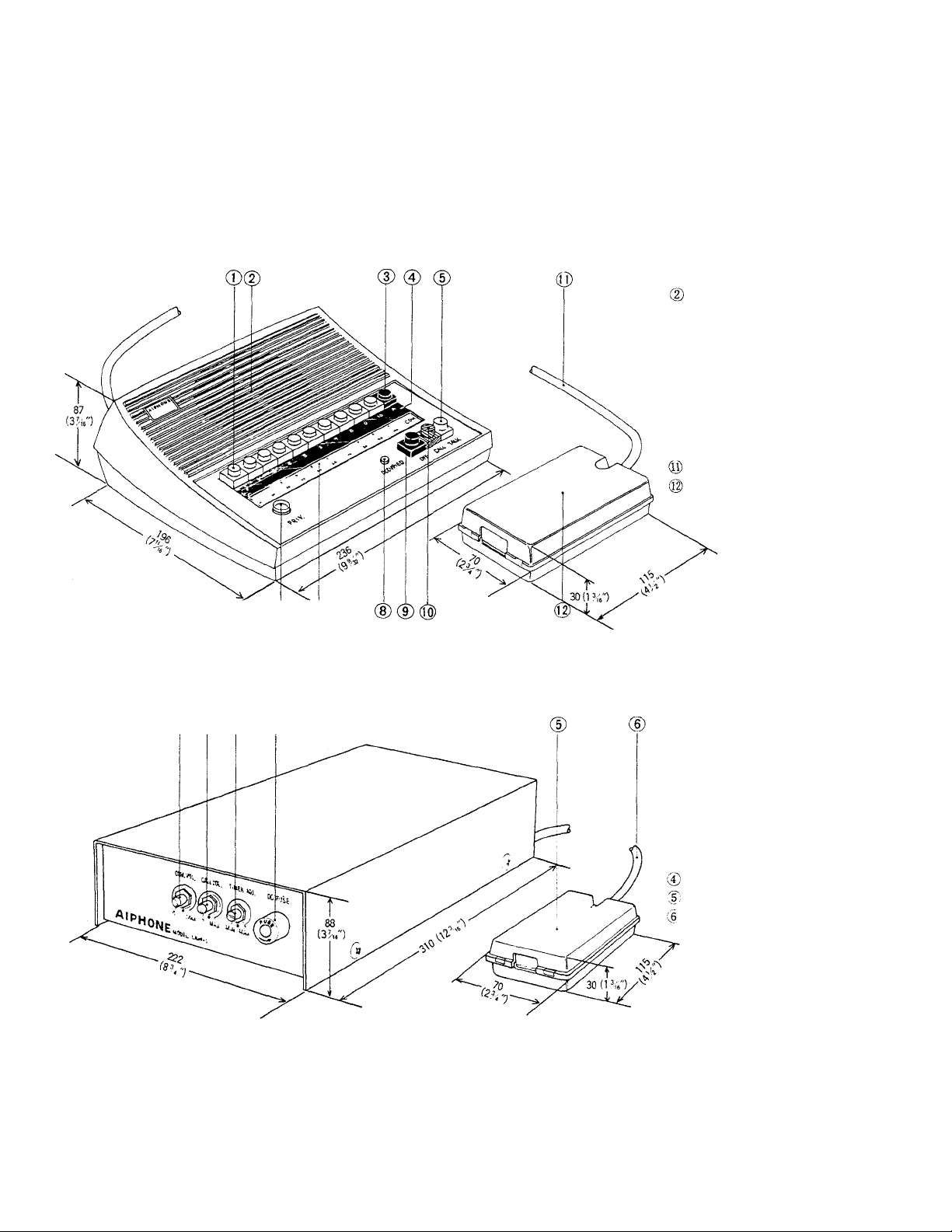
LAH-20
(D ©
INSTRUCTIONS -
I
(T) Selector buttons
Speaker/Microphonc
(D Expander button (A)
© Communication lamp
® Talk button
® Privacy button
@ Directory card
® Occupied lamp
® Off button
@ Call button
Terminal cord
Terminal box
LAW-1
© ® ® ®
© Volume control for
voice communication
% Volume control for
call tone
@ Timer control for
automatic reset
(adjustable fromapp.
30 to 120 seconds).
DC fuse (lA)
Terminal box
; Terminal cord
Page 2
SPECIFICATIONS
* Power source:
* Current consumption:
Amplifier output:
* Calling:
Wiring:
DC 12 volt. Use PS-12A (or PS-12C in North America) power supply.
lA maximum during talking per system.
800 mW maximum.
Push button station selection. Occupied lamp illuminates if the system is in use.
7 twisted pairs are required regardless of the number of installed stations. Each pair must
be twisted.
FEATURES
The central amplifier uses advanced integrated circuits providing excellent fidelity and trouble-free operation.
^ Automatic reset ensures that a station left on will not occupy the system (a warning tone sounds before the system
automatically resets).
' A local privacy button and incoming call tone prevent monitoring.
' Warning tone to both parties when called station is in privacy.
‘ Single channel amplifier positively jocks out a third party.
' Hands-free reply at called station.
' Binary computor circuit permits 20 stations to be connected using only 7-pair cable.
'■ Tone and communication volume controls are located on the central amplifier.
' Designed for desk or wall mounting (desk only with handset).
■ Field installed handset provides privacy at calling or receiving stations.
■ An extention talkback speaker may be connected to a LAH-20 station with LAN-1 adaptor.
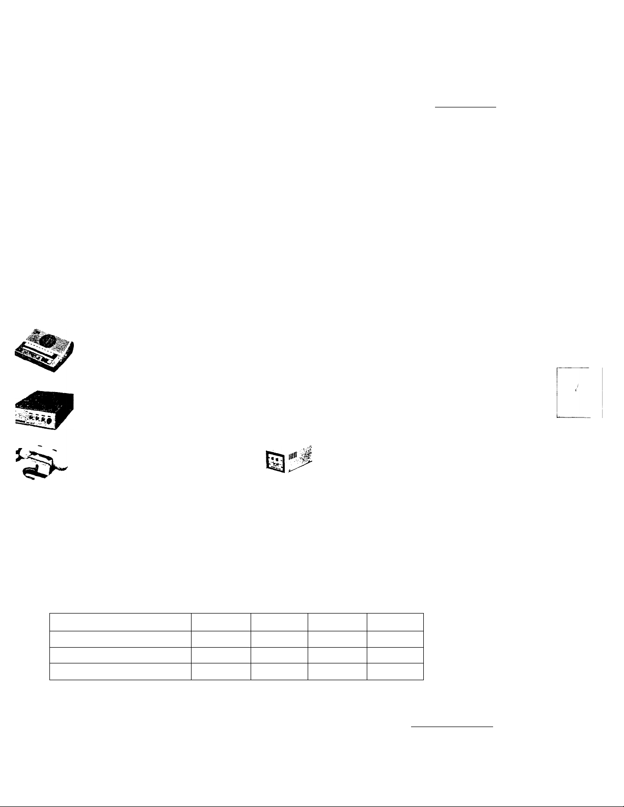
ÌQUIPMENT AVAILABLE FOR USE WITH YOUR LAH CENTRAL AMPLIFIER SYSTEM
I
i
LAH-20: 20 call master station.
LAN-1: Extention talkback speaker adap
tor. Connects LAH-20 master station to
a paging horn or speaker.
LAW-1 : Central amplifier.
PS-12C: CSA & UNDERWRITERS’ LABO
RATORIES, INC.® Listed power supply
(available only in N. America).
LAR-1: Optional handset. Includes press-
to-taik switch.
PS-12A: Power supply (not available in
North America).
MSTALLATION
Do not attempt to install your intercom system until you have read and thoroughly understood the installation
occdure. Aiphone's warranty is void if system is installed in a manner other than described in this manual.
IRING
Lay out your system in advance and determine a location of each station. Please refer to the chart below to select
oper size wire for your installation. 7 twisted pairs of wire are required regardless of the number of installed stations.
AWG WIRE SIZE
COMMUNICATION DISTANCE FROM
EACH STATION TO AMPLIFIER
DIAMETER OF WIRE
COMMUNICATION DISTANCE FROM
each station to AMPLIFIER
24 AWG
300'
0.5 mm
90 m 150 m
22 AWG
500'
0.65 mm 0.8 mm 1.0 mm
20 AWG
760'
230 m 360 m
18 AWG
1200'
Total iengtii of all communication wire installed per system should not exceed 2km or 1.25 mile.
Refer to the wiring diagram and write your color code in a space provided. Begin with the central amplifier and wire
first two stations, testing ¡item after installation. Unplug power supply while making connections. Refer to the table on
bottom of each station to assign that station’s number.
- 2 -
Page 3

LAH-20 ALL MASTER SYSTEM with I
p
STATION STATION STATION STATION STATION STATION STATION STATION STATION STATION
1
i 2 # 4 # 5
# 6
# 7
8
S 10
2) Each twisted pair must be connected to terminals #1 and #2, #3 and #4, #5 and #6, etc. Please refer to wiring diagram.
3) Wiring may be in a loop as shown above, or in a home-run manner.
4) We advise installing amplifier near the center of the system.
5) Connect the red and black wires within the amplifier to plus (+) and minus (—) respectively of the power supply. The
power supply may be mounted inside the amplifier cabinet.
CAUTION; DO NOT ATTEMPT TO CONNECT POWER SUPPLY TO LAH-20 MASTER STATION.
INSTALLATION FOR WALL MOUNTING
1) Attach the mounting bracket to wall or plaster ring.
2) Attach the master station to this mounting bracket.
3 -
Page 4

LAW-1 CENTRAL AMPLIFIER
STATION STATION STATION STATION STATION STATION STATION STATION
STATION
# 19
LAH-20
STATION
S 20
LAH-20
LIFIER
'-1
10^
11 n
12^
14^
S ,
©
©
S.
BLACK O
RED ©
V
10®
>
13
14®
s,
©
©
s,
V.
_
Tl2®
i
ll3
1
14®
S ,
©
©
y
Sa
II PS-12A or
V- PS-12C
POWER SUPPLY
DC-12V
HOW TO SET THE BINARY COMPUTOR
Please refer to the table to assign station numbers
to each of the intercom masters (Note: This
same table is on the bottom of each master).
Each intercom will have a separate number,
that is, station #1 will be programmed for one
intercom, station #2 for the next and so on
until all stations have been programmed. For
example, to program an intercom for station
#1, just refer to the ST No. 1 on the chart and
set “A” switch to 1 position and. set the
remaining switches “B”, “C”, “D” and “E” to
the O position.
STATION NUMBER COOING SWITCH
abode
E
A
B
0 0
0 0
0 0
0
0
0 0
0 0
0
1
0
1
0
1 0
0
0
0
0
0
0
0
0
c
0
1 0
0
0
0
0
0
0
0
D
0 1
0
0 0 2
0
0
0 4
0 0
0 0 6
0 0 7
1 0
1
0 9
1
0
1 1 A
0
0 1
0
0 t 4 A
0 5 A
0 6 A
0 1
1 9 A
1
1
-0
ST, No.
3
5
8
10
2 A
3 A
7 A
8 A
10A
Page 5

INSTALLATION OF LAR-1 OPTIONAL HANDSET
1) Remove four screws on the bottom of master station and lift the plastic case from the base.
2) Using a sharp knife, cut open between terminals A & B, and also C & D on the printed circuit board.
3) Using 8mm (K”) drill or soldering iron, make a hole to pass conductors into the body of master station.
4) Mount the handset to body of master station with supplied screws.
5) Connect the nine conductors from the handset to the printed circuit board. For full information please refer
to the instruction sheet packed with LAR-1.
NOTE: The LAH-20 master station with LAR-1 handset can not be mounted to wall.
LAH-20 SYSTEM WITH EXTENSION TALKBACK SPEAKER USING LAN-1 ADAPTOR
* Each LAH-20 master may be connected to one extension speaker.
* One extension speaker may be connected up to three LAH-20 masters but requires one LAN-1 adaptor per each
master.
* Extention speaker requirements; Either AlPHONE MODEL LA-A standard substation(speaker output O.SWmax.),
or locally available a 8 ohm paging horn (speaker output 1.2W max.) or a 16 ohm paging horn (speaker output IW
max.) may be used.
NOTE; The call switch in the LA-A can not be used.
* Wiring: Connect yellow, blue, black, white and red wires from LAN-1 to 5,6, 14, SI and S2 terminals on the
LAH-20 and then yellow and blue wires from the secondary side of LAN-1 to the extension speaker.
* In this example buttons #8-A on station #18 selects LA-A extension speaker and buttons #9-A on station #19 and
buttons #10-A on station #20 select paging horn.
STATION
# 16
STATION STATION
# 17
# 18
STATION
# 19
STATION
# 20
2)
NOTE: LAN-1 adaptor should be located near the LAH-20 master.
Distance from the LAH-20 master to extension speaker must not exceed 150m (450’).
- 5 -
Page 6

OPERATION
* Calling;
1) If the occupied lamp is not illuminated, select the station desired by depressing the proper button. Station #11 through
#20 are called by depressing the number button and then the expander button (A). Station #11 is 1-A, Station #12 is 2-A, etc.
2) Depress call button to establish communications and signal the called station.
3) If a steady tone is heard, the called station is in privacy. By pressing the call button, the called station will be notified that
it is in the privacy mode.
4) Use the talk button to control communications. If using the optional handset, use the talk switch in the handset to control
communications.
5) Depress the OFF switch at the end of every conversation (the selector button may remain in depressed position).
If you forget to depress the OFF switch, a warning tone will notify you that your station is on.
* Receiving;
The open voice feature allows handsfree operation. The privacy switch locks out monitoring or eavesdropping. The
call light will illuminate, however, even if in privacy, and call tone will sound. The call may be answered by releasing the privacy
switch or by using the handset.
* To call extension speaker;
Extension speaker, if installed to your LAH-20 master, may be called by depressing the selector button corresponding to
your station number and then the call button. Selector button #1 on master #1, selector button #2 on master #2, etc. selects
respectively each speaker. Operation is exactly same as communication with other master station.
CLEANING YOUR INTERCOM STATIONS
* Your Aiphone intercom stations may be cleaned with a soft cloth dampened with household cleanser, such as Mr. Clean or
Fantastik,
* 4: ♦
We at AIPHONE are proud of our products. Our designers and engineers strive to bring you the fmest in communication
equipment. Each item has been carefully tested and inspected before leaving our factory. Properly installed and used, your
Aiphone intercom system should give years of troublefree service.
We are pleased to offer the following warranty:
WARRANTY
Aiphone warrants its products to be free from defects of material and workmanship under normal
use and service for a period of one year after delivery to the ultimate user and will repair free of
charge or replace at no charge, should it become defective upon which examination shall disclose
to be defective and under warranty. Aiphone reserves unto itself the sole right to make the final
decision whether there is a defect in materials and/or workmanship; and whether or not the prod
uct is within the warranty.
This warranty shall not apply to any Aiphone product which has been subject to misuse, neglect,
accident, or to use in violation of instructions furnished, nor extended to units which have been
repaired or altered outside of the factory.
This warrantv does not cover batteries or damage caused by batteries used in connection with the
product.
This warrantv covers bench repairs only, and any repairs must be made at the shop or place des
ignated in writing by Aiphone. Aiphone will not be responsible for any costs incurred involving on
site service calls.
Aiphone Co.. Ltd., Nagoya, Japan
Aiphone U.S.A.. Inc., Bellevue, Washington
LAH-20 1-0278®
all over the world AIPHONE
PRINTED IN JAPAN
 Loading...