

Page 1
f HOME INTERCOM
MODEL:
V
____
INSTALLATION MANUAL
LAF-7B
831277 0387 ®
Master station
7-call
semi-flush mount
O AlPHONE
Mounting accessories:
WOOD SCREW (4.“} x 22 ±) (x 4)
2-PIN CONNECTOR
(Attach on LAF-7B
when system includes
existing LAP models}.
9-PIN CONNECTOR
(for station wiring)
11-PIN CONNECTOR
(for station wi ring)
J
Mounting back box (Model; BBX-1)
SCREW (4 X 25 ±) (x 4)
*Must be ordered separately.
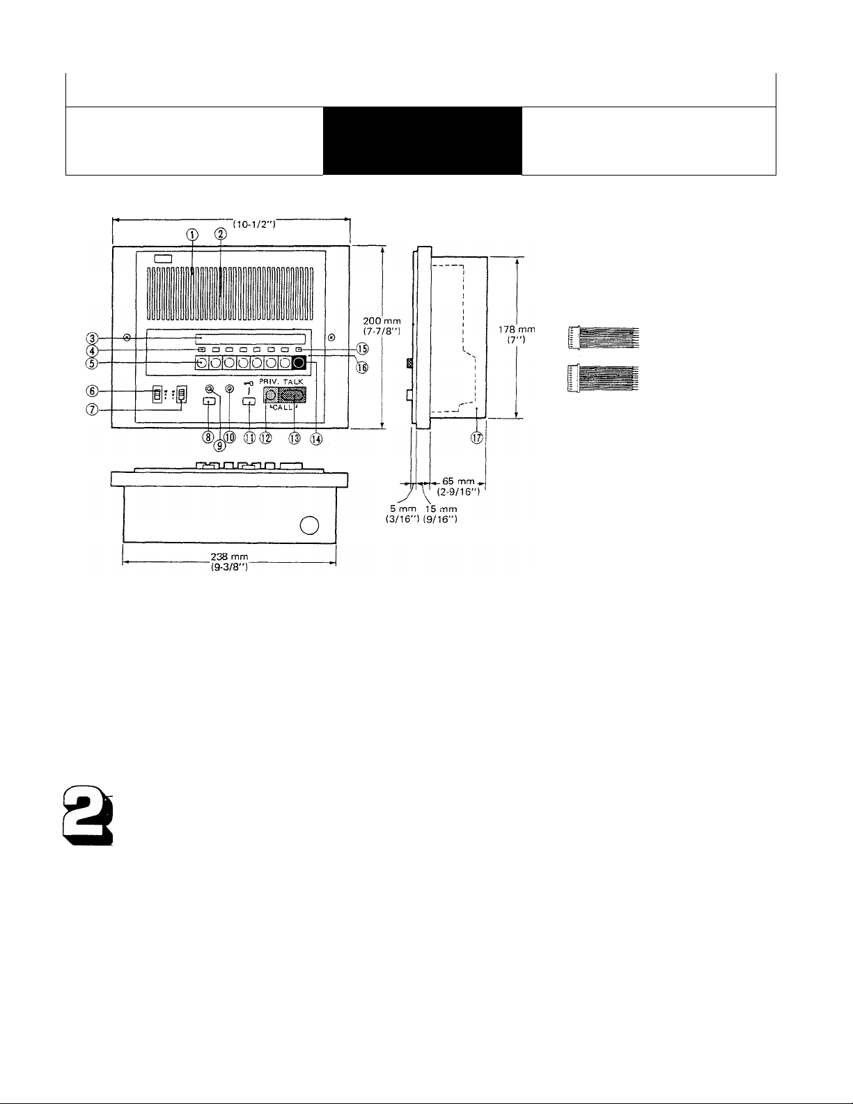
NAMES AND FUNCTIONS
© Speaker
@ Microphone
(D Directory card
® Call annunciator LED
® Station selector button
® Communication volume control
@ Call tone volume control
® ALL CALL button
ALL CALL indicator LED
OCCUPIED LED
Door release button
PRIVACY button
TALK button
OFF button
Station selection indicator LED
Panel
Mounting back box (Model; BBX-i)
SYSTEM FEATURES
Versatile communication system. Either All-master, Single-master or Intermixed System can be created.
Intemixable masters and subs, either semi-flush mount (LAF-B) or desk/wall mount type (LAF).
All Call announcement and Background music distribution, using BG-IA/IB and an amplifier.
All call announcement may be initiated in occupied mode when the system consists of LAF-7B and LAF-1B/3B/10B
(Type A) stations (with no existing LAF-lOB or LAF console stations intermixed).
Handsfree reply and high output power.
Sub call-in annunciator LED stays lit for approx. 20 seconds.
During your communication, sub call-in can be signalled by soft tone.
Options; ♦ Door station (any number). * Door release, using RY-PA relay.
* Paging thru an 8-ohm horn with talkback.
Page 2
BEFORE YOU INSTALL AND OPERATE THE EQUIPMENT
— Prohibitions and precautions —
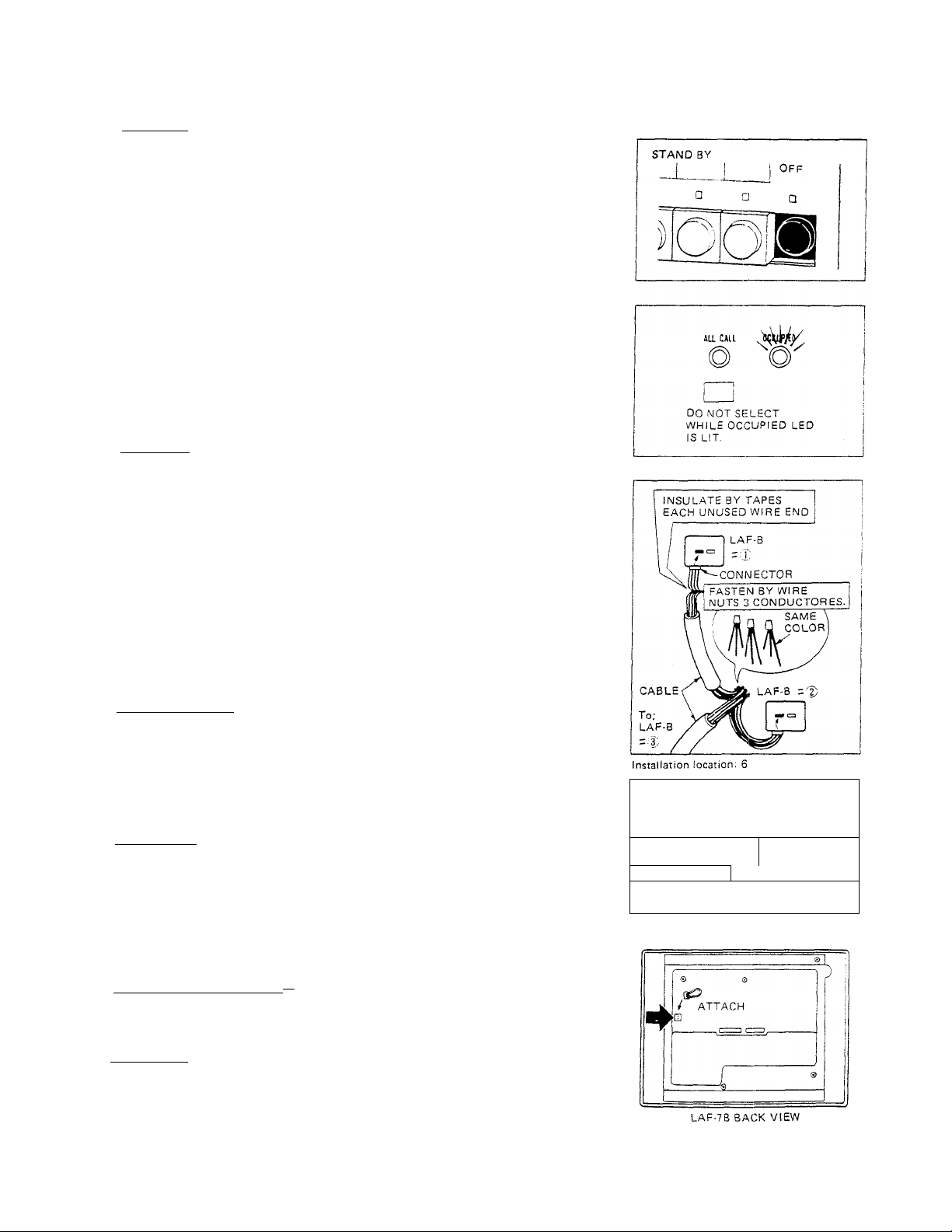
*Ope ration;
1. On all LAF master stations, except station initiating a call, OFF button MUST
BE DEPRESSED and LOCKED DOWN, or system will not work. The illumi
nated LED above OFF button indicates you forget to depress OFF button, if
not in use.
2. The illuminated OCCUPIED LED indicates the other station is using the sys
tem. While this OCCUPIED LED is lit,
(1) Do not depress any selector button. The squeak sound will come out at
initiating and receiving stations.
So, when you receive calls from another master and a sub at the same
time, REPLY FIRST TO THE MASTER and, after the OCCUPIED LED
goes out, depress a selector button of the calling sub and communicate.
(2) Do not make All Call nor any other operation, when LAF-B units are
intermixed with existing models (LAF-3A/5/10/10S/10B/I0BS).
3. When a sub station calls during Background music distribution, the call tone
will come out through all LAF station speakers, and call-in annunciator LED
stays lit for approximately 20 seconds on the called master station.
* Installation;
1. DO NOT CONNECT ANY TERMINAL ON .4NY UNIT TO AC POWER
LINES.
2. Be sure not to plug power supply into AC receptacle until you complete
wiring connections, and unplug before opening the unit.
3. Lay out your system in advance. Determine the exact location of each station.
Assign station number and make a sketch showing the number of wires and
color codes from one station to another. Begin your installation with master
station No. 1. Upon installing second master station, we recommend a test be
made for ail functions, calling and talking between each station.
After completing all the masters connection and testing, begin sub station
installation.
4. Insulate by tape, etc. each unused connector wire end. If touches the other
wires or back box it will cause damage to the units.
Installation location;
5. Select the installation locations that would not be exposed to temperature/
humidity extremes, water, oil, dust, iron dust, inflammable and chemical
products, etc.
6. To avoid feedback, DO NOT PLACE MASTER STATION AND ANOTHER
MASTER OR SUB STATION BACK TO BACK, OR ON A COMMON WALL
BETWEEN ROOMS.
Unit selection;
7. When making an intermixed system, note in advance that master stations:
LAF-3A, LAF-5, LAF-10 console types have no button for All Call nor door
release. LAF-lBand LAF-3B have only door release button. If such functions
required at console type station, please use LAF-1 OS.
8. If any LAF-B station: LAP1B/3B/7B/10B (Type A) is intermixed with existing
models: LAF-3A/5/I0/1Q6/10B, install a supplied 2-pin connector on back of
all the LAF-B units.
Adaptor installation location;
9. Locate PS-12A (or PS-12C) power supply near center of the system.
10. Locate BG-IA/IB adaptor near by the power supply.
* *
Installation: 4
ROOM 1
/
WALL
\
r
...........
ROOM 2
Unit selection: 8
NEVER
--------------1
1
.
LAF-n8
LAF-n8
*Maintenance;
1. Clean your equipment with a soft cloth dampened with neutral household
cleanser. Never use thinne nor benzine, etc.
— 0 .
Page 3
*Volume adjustment;
LAF-B unit has pre-setting volume, allowing to lower the maxumum level of
communication. On back of LAF-B unit, using a philip screwdriver, turn the
volume counter-clockwise to achieve the desired level.
On front panel, LAF-B unit has two volume controls for communication and call
tone, each adjustable to three levels as desired.
ACTUAL TERMINAL LOCATION
COMMUNICATION VOLUME
LAF-78 BACK VIEW
Max. communication pre-set
volume control
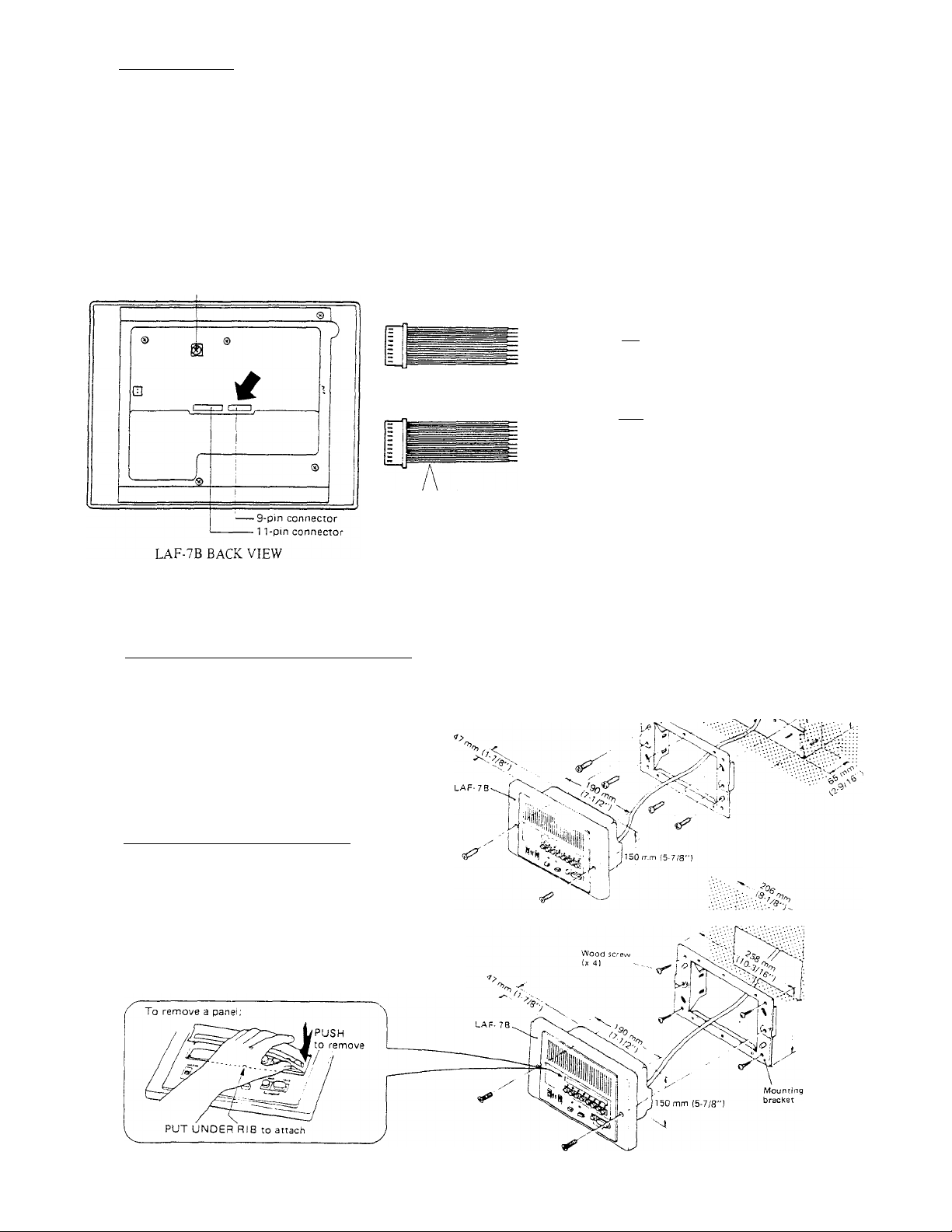
INSTALLATION
3
(1) Semi-flush mounting to wall (in new construction);
For new construction, use a mounting back
box (Model: BBX-1).
1. Install the back bo.x in the wall.
2. Attach the supplied mounting bracket with
four screws (supplied).
3. Mount LAF-7B unit to the bracket with two
screws (supplied).
9-pin connector with 7 wires of approx. 22 cm
(8-5/8”)
1 Tpin connector with -
10 wires of approx. 22 cm
(8-5/8”)
PIN/WIRE COLOR CODE
1. Brown 5.Green
2. Red 6.Blue
3.Orange 7.Purple
4.Yellow 8. —
- I'Ti for connecting station unitjTI ~ [T]
for receiving a call and BGM
(~7 for power supply
s
for common communication
for occupied lamp
for .All Call control
fPTi for All Call output
s
CD
NDENTlFiCATlON
for sub call-in tone during
communication
for door release control
9. -
10. -
C. Brown
£. Orange
Mounting
aack box
(BBX-1)
Y. Yellow
Pj . Green
P;. Blue
P
3. Purple
R. Gray
L. White
+ . Red
—. Black
ra'-.
>-
(2) Semi-flush mounting to an existing wall;
1. To install LAF-"?B unit to an existing
wall, cut and open a hole of H: 165 mm
(6-1/2") X W: 206 mm (8-1/8"), securing
depth of more than 47 mm (1-7/8"),
2. Attach the mounting brocket directly to
wall with four wood screws (supplied),
3. Mount LAF-7B unit to the bracket with
two screws (supplied).
.'•'•.■.•'•,1 65 mm
1 92 mm j
|7-9/16"1 '■•••
- 3
Page 4

SPECIFICATIONS
*Power source:
*Current consumption:
*Communication:
*Communication output:
*Communication network:
* Calling:
*Talk channel:
*Wiring:
"Wiring distance:
DC 12V. Use PS-12A (or PS-12C in North America) power supply.
350 mA maximum.
Press-to-talk release-to-listen at calling master.
800 mW maximum at 20 ohm.
Either of All-Master, Single-Master or Intermixed System can be created.
Electronic tone and an illuminated LED (staying lit for approx. 20 seconds), when called by sub
(at master)
Electronic tone or Voice direct when called by master (at master)
Electronic tone or Voice direct when called by master (at sub).
1 talk channel.
0 Between master stations;
Between masters
For communication only 5 common + 1 individual
For communication and
BGM reception
For communication and
All Call transmission
For communication,
BGM reception and
All Call transmission
For door release
For all functions as above 9 common -i- 1 individual
0 Between sub station; 3 wires for each sub station.
Between two farthest master stations;
5 common 1 individual
8 common + 1 individual
8 common + 1 individual
plus 1 common (additional)
Between masters & BG-1 A/1B
4 common + 1 individual
7 common + 1 individual
7 common -i- 1 individual
7 common h- 1 individual
*Dimensions:
Recessed:
*Back box diamensions:
*Weight:
*RY-PA relay contact
capacity:
Aiphone Co., Ltd., Nagoya. Japan
Aiphone Corporation, Bellevue, Washington
AWG
Distance
Diameter 0.5 mm
Distance
H : 200 mm
(H : 7-7/8"
H : 150 mm
(H : 5-7/8"
H : 178 mm
(H : 7"
Approximately 1,020 g(2.25 lbs.)
AC llOV, lA.
DC 24V, lA.
24 AWG
400' 650' 1,000'
120 m
W : 266 mm
W : 10-1/2"
W : 190 mm
W : 7-1/2"
W : 238 mm
W : 9-3/8"
-4-
22 AWG 20 AWG
0.65 mm
200 m 300 m
: 20 mm
: 13/16")
; 47 mm
1- 7/8")
65 mm
2- 9/16")
0.8 mm
O
IN I bRCOM SYSTEMS
AIPHONE
HOME, BUSINESS, INDUSTRY
PRINTED IN JAPAN (E)
Page 5

WIRING DIAGRAM
#ф LAF-7B ALL-MASTER SYSTEM
♦ROOM-TO-ROOM COMMUNICATION
*BGM RECEPTION/ALL CALL TRANSMISSION
BGM reception/All Call transmission
(at any room station)
(1) When using a STEREO MUSIC SOURCE, eg. FM Tuner,
8-track player or cassette player, etc., connect the PHONO
plugs directly to two PHONO jacks on BG-1A/IB.
(2) Music source output requirements;
Tuner; Use AUDIO output (Range; 300 mV ~ 1.2V,
10 К ohm ~ 100 К ohm).
Tape player; Use low level output (Range: 300 mV ~
1.2V, more than 600 ohm)
(PS-12A/PS-12C)
Communication
Each own number button connects to a last station No. 8.
Page 6

# @ LAF-7B ALL-MASTER SYSTEM
WITH ONE EACH DOOR STATION & DOOR RELEASE AND BGM/ALL CALL
CONNECTOR WIRE
COLOR CODES
9 1
P
1
N
7
W
R
E
11
P
1
N
10
w
1
R
E
Brown
2 Red
3 Orange
4
Yellow
5
Green
6
Blue
7
Purple
-
-
—
c Brown
E
Orange
Y
Yellow
Green
Pi
Blue
Pj
Purple
Ps
R
Gray
L White
+
Red
Black
-
*ROOM-TO-ROOM COMMUNICATION
* DOOR STATION CALL-IN
* DOOR RELEASE
*BGM rTception/all call transmission
BGM reception/AU Call transmission
(at any room station)
(1) When using a STEREO MUSIC SOURCE, eg. FM Tuner,
8-track player or cassette player, etc., connect the PHONO
plugs directly to two PHONO jacks on BG-1 A/1B.
(2) Music source output requirements;
Tuner; Use AUDIO output (Range: 300 mV ~ 1.2V,
10 K ohm ~ 100 K ohm).
Tape player; Use low level output (Range: 300 mV ~
1.2 V, more than 600 ohm).
Door station communication Door release
Door station call can be received at max. two room
stations (Nos. (O and (|) in the above diagram).
So, do not connect each own number terminal on all
the room stations except Nos. © and @.
* Connect [y terminal on room stations Nos.
© and @, accepting doorphone call.
*Use a bell transformer: AC 12V, 0.25A or more to
power EL-9S.
* Separate wiring for door release from wiring
for communication.
Page 7

#© lL
a INTERMIXED SYSTEM
WITH ONE EACH DOOR STATION, DOOR RELEASE & 3-CALL SUB AND BGM/ALL CALL
jou
OUTPUT INPUT
PAGINA AMP
PG-10A/PG-10B
C=D
BG M
SOURCE
BGM/ALL CALL
ADAPTOR
(BG-1A/1B)
Q
Q
H
Q
S
S
MUSICI
INPUT
©
MASTER STATIONS STATION
(LAF-7B) (LAF-7B) (LA-D/DA)
DOOR
#® #@ #®
0
{1}
[I>
Q
0
0
0Ì—CU
0
0
0
0
0
0
0
1-CALL
MASTER
(LAF-1B)
0
SUB
(LA-B/BN)
[+l---r+l—FR-
—
,-BLACK^
SUB
(LA-B/BN)
0
15 mfd
non-polar
\^RED
LT-1
BLUE
BLUE'
*ROOM-TO-ROOMCOMMU, aTION
(MASTER-TO-MASTER,
MASTER-TaSUB)
* DOOR STATION CALL-IN
* DOOR RELEASE
* MASTER ALDCALL TRANSMISSION
*BGM RECEPTION AT MASTERS &
3-CALL SUB
*LA-A3/AN3 SELECTIVE CALL TO
MASTERS
NOTES;
A call from sub Nos. 1 ~
©
3 signalls two
masters simultaneously.
Sub No. 5 can call and
@
each master selectively
communicate
and receive
BGM and AH Call.
Sub No. 4 can only receive BG.Vl and
All Call. If talkback is required, con
nect the wire to a vacant No. terminal
on LAF-7B master.
SUB
8-OHM
HORN
3-CALL
SUB
(LA-A3/AN3Ì
0 LAF-IB (No. (3)) can call a master
No. 0 and also receive BGM/AU Call
LAF-7B
CONNECTOR WIRE
COLOR CODES
1 Brown
2 Red
3 Orange
4 Yellow
5 Green
Blue
6
7 Purple
-
-
—
Brown
c
E Orange
Y Yellow
Green
P.
Blue
Pj
Purple
P3
Gray
R
White
L
+
Red
-
Black
RY-PA
POWER SUPPLY
Page 8

#(4) LAF-7B INTERMIXED SYSTEM
LAF-7B
CONNECTOR WIRE
COLOR CODES
9 1
P
1
N
7
W
R
h
11 C
P
1
N
10
W
R
E
Brown
2 Red
3
Orange
4
Yellow
5
Green
6 Blue
7
Purple
Brown
E
Orange
Y
Yellow
Green
Pi
Blue
Pj
Purple
Рз
R Gray
L
White
+
Red
- Black
_
-
—
»COMMUNICATION BETWEEN MASTERS
*(No communication between LAF-3A masters)
»DOOR STATION CALL-IN
»DOOR RELEASE
NOTES;
® When intermixing LAF-7B units with
LAF-3A/5/IO/IOS units, install a
supplied connector on back of each
LAF-7B. And [Y] terminals on
LAF-7B units may remain uncon
nected.
LAF-3B and LAF-3A stations can
call each LAF-7B station, but can
not communicate with each other.
Ah Cah announcement is available
from LAF-7B stations. LAF-3B and
LAF-3A stations have no All Call
button and can only receive All Call
and BGM.
® When using a MONO MUSIC SOURCE,
eg. FM tuner, 8-track player or cassette
player, etc., cormect the PHONO
plug to either PHONO jack on BG-IA/
BG-IB.
»Music source output requirements;
Tuner: Use AUDIO output (Range;
300 mV ~ 1.2V, 10 К ohm ~ 100 К
ohm). Tape player: Use Low LEVEL
output. (Range 300 mV ~ 1.2V,
more than 600 ohm).
 Loading...