

Page 1
SPECIAL
ORDER
PRODUCTS
®AI PHONE
LOUDSPEAKER INTERCOM SYSTEM
MODELS LAF-20 (twenty call master station)
LAF-20S (twenty call master with
all-call & door release)
— INSTRUCTIONS —
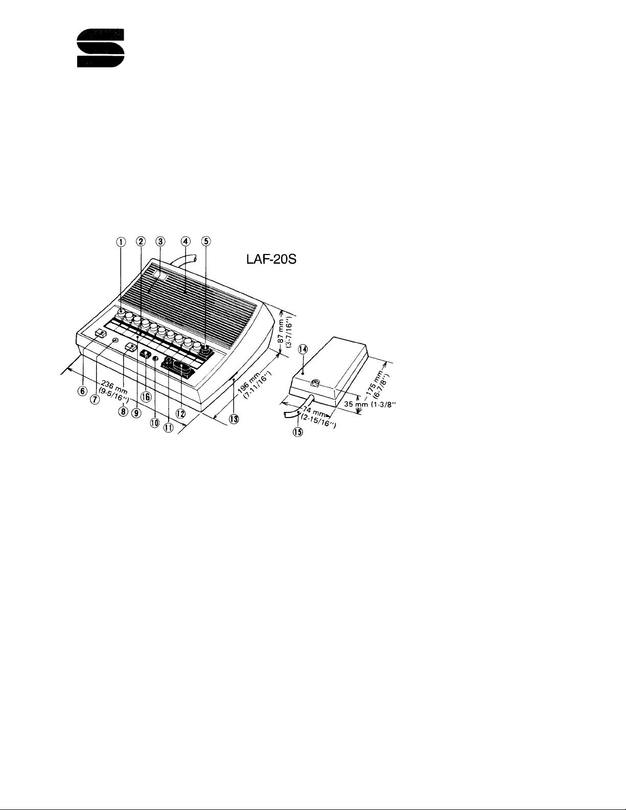
NAMES & FUNCTIONS
Selector button
Annunciator light
Microphone
Speaker
“A” button
Off button (LAF-20)
All-call button (LAF-20S)
All-call output indicator
(LAF-20S)
Door release button
8
(LAF-20S)
Directory card
9
10
Occupied light
Privacy button
11
Talk button
12
Communication volume
13
Terminal box
14
Terminal cord
15
Off button (LAF-20S)
16
SPECIFICATIONS
★ Power source:
★ Current consumption:
★ Power output:
★ Communication:
DC 12V. Use PS-12C Power Supply.
350 mA maximum per station.
800 mW maximum at 20 ohms.
Push button station selection. Calling by tone or voice. Press-to-talk
operation at calling master.
★ Door release switching
contact capacity:
FEATURES
AC 240V, lA; DC 30V, lA.
★ Background music (and all-call w/LAF-20S) can be included using BG-IAC/PG-KC
and PG-30A.
★ Straight paging is available using an 8-ohm horn and PG-3 Paging Amplifier.
★ Hands-free reply and high power output allow use in large or noisy areas.
★ Single talk path.
★ Includes a button for door release (LAF-20S).
★ Individual volume controls for communication and call tone on each master.
★ Privacy button helps prevent eavesdropping.
★ Several different substations to suit various needs.
★ Timer circuit turns off annunciator lights in approximately 20 seconds.
★ Designed for desk or wall mount.
★ Optional field installed handset for private communication (desktop only).
— 1 —
Page 2
INSTALLATION
Do not attempt to install your LAF master stations until you have read and thoroughly under
stand the installation instructions. Aiphone’s warranty is void if the system is installed in a manner
other than described in this manual.
ACTUAL TERMINAL LOCATION
: Connect to relative stations.
: Receiving a call and BGM.
: Power supply connection.
; Common connection.
A3 A2 A1 L L 10 9
7 6 5 4 3 2
1 - AlO
C
-f , E
R
: Occupied light control.
L , L : Door release contacts.
+ P3 P2 PI E R C A10A9 A8 A7 A6 A5 A4
PI
: All-call control.
P2 , P3 : All-call output.
WIRING
Lay out your system in advance. Determine the exact location of each station, and make a
sketch showing the number of wires required from each station to the other stations. Assign station
numbers at this time.
Refer to the chart below and select the proper wire gauge to meet your specific distance
requirements.
AWG WIRE SIZE 24 AWG
DISTANCE
400' 650' 1000'
22 AWG
20 AWG
18 AWG
1600'
Begin your installation with master station All masters included in your system should be
connected and tested before beginning substation installation. Note the position of the (C) terminal on
each master station, and be sure that each station is wired correctly.
After installing your second station, we recommend the power supply be connected and a test
be made of all functions, calling and talking between each station. Unplug the power supply before
making any additional connections.
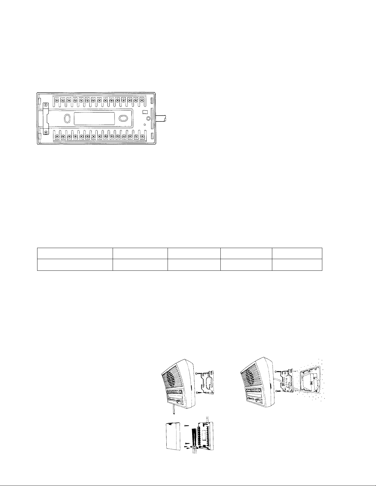
WALL MOUNTING INSTALLATION
1) Attach mounting bracket to wall
or box with supplied screws.
2) Mount station on bracket.
TERMINAL BOX INSTALLATION
1) Remove screw and cover as
shown.
2) Mount bottom case to wall or
The Terminal box may be mounted
inside 3-gang box.
box with supplied screws.
3) Wire terminals as necessary and
replace cover.
- 2
Page 3
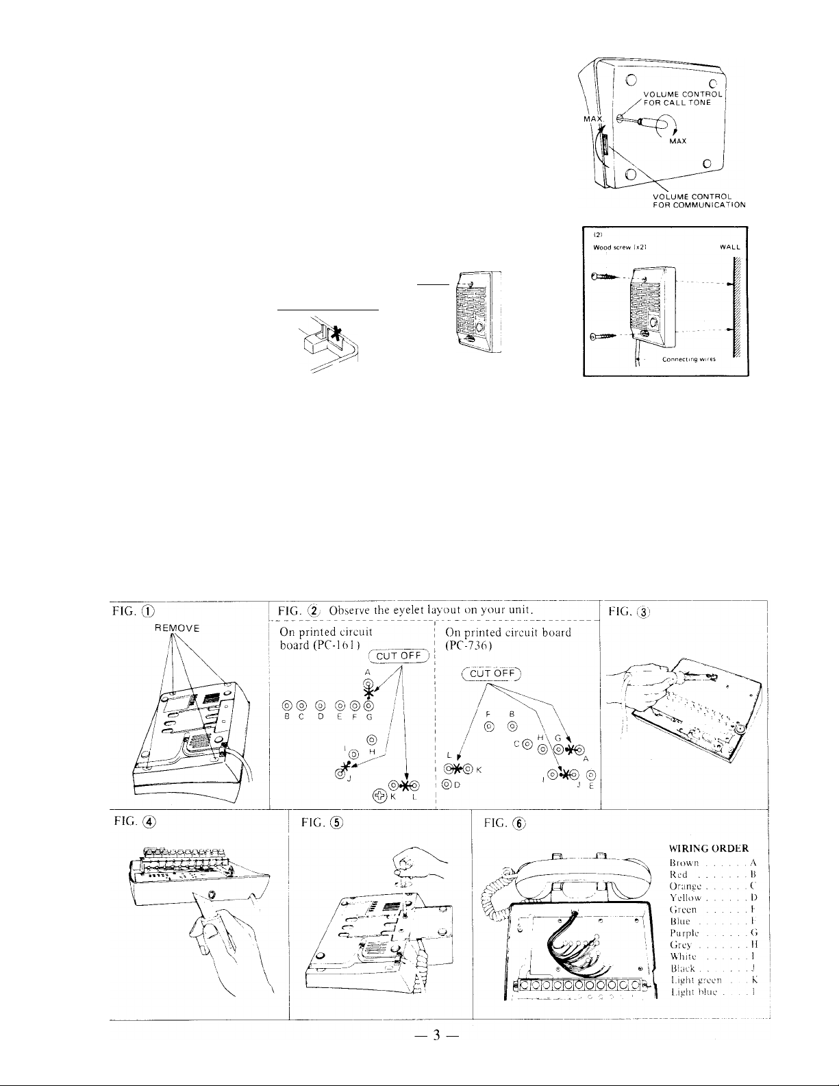
ADJUSTING VOLUME CONTROLS
Fingertip adjustment ensures pleasant communication at the
desired level all the time.
Use a screwdriver to adjust the call tone volume control to the
desired level.
LA-D INSTALLATION
1) Attach unit to a single gang box with the
screws provided.
2) When mounting to wall, wires may be
routed thru the top or bottom of the back
case. As shown, cut
CUT OU T
(1)
Screw (x21
PhJiltlliin
Connecting Gang
Js3 5 mm
1 (3-5/16")
out the thin part of
case when passing
wires thru top.
INSTALLATION OF LAR-2 OPTIONAL HANDSET
BACK VIEW
(TOP. BIGHT)
1) Remove the 4 mounting screws on bottom of the master as shown in Fig. 1, and lift the plastic case
from the base.
2) Using a nipper or soldering iron, remove the jumpers between A & G, I & J, and K & L on the
printed circuit board as shown in Fig. 2.
3) Make a hole in the body of the base to pass the wires thru using a soldering iron, '/4" or 8mm drill
as shown in Fig. 3. If a soldering iron is used, clean away the burned plastic with a sharp knife as
shown in Fig. 4.
4) Route the wires into the base and mount the handset with screws provided as shown in Fig. 5.
5) Solder the 12 wires from the handset to the printed circuit board as shown in Fig. 6. Be sure the
wires are in the correct order.
6) Replace the plastic case and reinstall the mounting screws.
Page 4

WIRING DIAGRAM #1
The following diagram illustrates an intermixed LAP system. All stations connected to the
BG-IAC/PG-KC will receive all-call announcements and BGM. Substations must be connected to the
BG-IAC/PG-KC thru a 15 mfd bipolar capacitor as shown (if BGM/all-call is desired), or the system
will not work.
NOTE: Remove the shorting link attached to the (E) and ( —)
terminals on all substations
as shown if your system
uses 2 or more masters. In
this case, 2 common and 1
individual wire per sub are
required.
SUB 1
0
SUB 2
.0
,0
r0
0
■0
SUB 3
,0
0
0
DOO R
STA TI ON
r0
0
POW ER S UP PL Y
0
MAS TE R 1
LAF -2 0S
.0
0
’ s
0
,0
10
,0
A1
0
A2
0
A8
0
A^
0
AlO
0
0
0
MAS TE R 2
LAF -2 0
ci
A
c*
s
10^
A1^
S
A8
A9^
AlO
Ok
20
Ol
Ol
MAS TE R 3
LAF -2 0S
1^
o,
2^
A
10^
o>
A1^
r>
kP
kP
S
A8^
A9
AlO AlO
MTS TE R
LAF -2 0
A1^
A2^
A3^
10^
10
p
2^
P-
c®
p
_Ol
P
S
P
kP
P
P
P
E0
Ok
LA- A
LA- A
LA- A
NOTE: Separate AC trans
former (PT-1210) is
required to power
door release. Wiring
should be separated
from communication
wiring to avoid noise
from activated door
release.
LA- 0
PT- 12 10
TRA NS FO RM ER
EL- 9S
,0
PS- 12 C
0
>0
4
_
Ol
_
Ol
P-
P1^
_
p
P2
_
P
P
Ok
P3^
Ok
P
Page 5

The LA-D Door Station below is connected to the first 6 masters shown and will annunciate a
call at each simultaneously, but is not wired to receive all-call or BGM. Only masters #1, 3, 11 & 18 are
wired to activate the door release.
NOTE: Substations cannot be wired to call more than 6 master stations without modification. Contact
Aiphone’s Technical Sales Staff for information.
—
MAS TE R 11
LAF -2 0S
2^
jTìl
10^ 10^
c*
aP
/TX
aP
s
/TX
A8
A9
AIO
Ol
A1^
rx
MAS TE R 12
LAF -2 0
p
rx
/A
rx
A1^ a”
fA
A7
A
A8
“V?
A9
A
AIO
A
A2
MAS TE R 18
LAF -2 0S
1^
-A
2^
A-
3^
^ S
10^
A
A
A2^ A2^
A
A7®
C*
A
A9
(A
AIO
A8
A
A
MAS TE R 19
LAF -2 0S
1^
2^
A
S
10^
A1^
A
S
A7^
A8
A
C®
AIO
A®
A9
A
E^
A
MAS TE R 20
LAF -2 0S
r0
r0
0
10
0
A1
0
A2
0
A7
■ 0
A8
0
A9
0
A10
0
0
15u FB P
^hт0
BG- 1A C
0
0
0
10
0
0
(SH IE LD ED )
15u F BP
H hfT0
ISu FB P
1-70
PG- KC
0
0
?
s
0
8
0
0
10
0
0
-++-
• ^
BGM
SDU RC E
-©
PG- 30 A
0]
P3
eP
pP
pP
L0
rx
rx
rx
rx
rx
rx
/Ok
Ok
P1^
P2
P3^
i:£
A
A
A
A
-A
A
0
A
R^
A
Pl^
__
A
P2^
A
_
P3
L®
A
L®
-
R
Pi
P2
P3
0
0
0
0
5 -
P^V^
0
P2
0
P3
0
P4
0
0
V
V
P4
0
0
0
0
0
25V
0
com
izm
0
Page 6

WIRING DIAGRAM #2
The diagram below illustrates a typical single master system with an NP-B Call-in button, AH-
108 Horn Speaker, and an LT-1 Matching Transformer installed. In operation, the horn speaker will
function just like a standard substation.
LAF-20
NOTE: If your system consists of just I master and several
subs, only 2 wires per sub to the master are required.
Leave the (E) and ( —) terminals on all subs shorted
together. Also, make a jumper and short the (E) and
( —) terminals on the master station terminal box as
L+’ V + ’<'1
shown.
OPERATION
MASTER STATION
★ Illuminated Occupied light indicates another master is using the system. Make your call once the
light has gone out.
★ Placing a call;
1) Depress the selector button for the desired
station.
2) To call by tone, momentarily press both PRI
VACY and TALK buttons. To call by voice,
depress the TALK button and speak.
3) Depress the TALK button to speak, release
to listen. If using LAR-2 handset, use the
Call by voice j
TALK switch in the handset to control
conversation.
4) Upon completing conversation, press the
OFF button and release the depressed selec
tor button(s) by pressing any other selector
button half way down.
-6-
Page 7

NOTE: The LAF-20/20S master station must be placed on standby after each conversation by press
ing the OFF button and releasing any depressed selector switch button(s) as described, or the
system will not work.
★ Receiving a call from another master;
1) If your station is in a non-privacy mode, no action is
necessary; communication is hands-free.
2) If the PRIVACY button is depressed, release it by
momentarily pressing the TALK button, then resume
hands-free operation. Reply can be made privately by
using the LAR-2 handset, if installed.
PRIVACY button pops up by momentarily
depressing TALK button.
NOTE: There is no LED annunciation between masters except the Occupied light.
★ Receiving a call from a substation:
1) An incoming call is annunciated by both tone and light. Depress the selector button above the
lighted annunciator light.
2) Press the TALK button to speak, and release to listen.
3) Upon completing conversation, press the OFF button and release the depressed selector button(s)
by pressing any other selector button halfway down.
4) If privacy is desired, depress and lock the PRIVACY button down.
NOTE: When receiving a call from a master station and substation simultaneously, reply first to the
master. Then, after the Occupied light has gone out, depress the selector button above the
lighted annunciator light and communicate. DO NOT DEPRESS THE SELECTOR BUT
TON WHILE THE OCCUPIED LIGHT IS ILLUMINATED.
★ Operating electric door release (LAE-20S only);
Door release mechanism is activated by pressing and holding the door release button until the door is
opened by someone.
★ All-call announcement (LAF-20S only);
1) If the Occupied light is not on, depress and lock the ALL-CALL button down. A pre-tone will
sound at all stations connected to the BG-IAC/PG-KC, and BGM will he cut off automatically.
2) Make announcement while pressing and holding the TALK button.
3) After making announcement, release the ALL-CALL button by pressing it again.
NOTE 1: DO NOT MAKE ALL-CALL ANNOUNCEMENT WHILE THE OCCUPIED LIGHT
IS ON.
NOTE 2: All-call announcement cannot be made thru the LAR-2 handset.
★ Distributing Background Music (BGM);
1) Turn on the ON/OFF switch for music on the BG-IAC as well as the BGM source/amplifier. BGM
will be distributed to the selected stations until interrupted automatically during communication.
2) When BGM is not desired, turn off the ON/OFF switch on the BG-IAC.
NOTE: A low volume call tone from a substation may be announced at all masters while BGM is
being distributed. Only the annunciator light on the called master will light, and will time out
normally in about 20 seconds.
SUBSTATION
★ LA-A, LA-D & LA-AN;
1) Momentarily press the call button to call the master. If a tone is heard, wait for the master to
answer. When the master replies, communication is hands-free.
2) If no call tone is heard when the call button is pressed, the system is occupied. Try again later.
★ LA-A3 & LA-AN3;
1) Momentarily press the call button for the desired master (unlock the PRIVACY button first on the
LA-AN3). When the master replies, communication is hands-free.
2) If no call tone is heard when the call button is pressed, the system is occupied. Try again later.
- 7 -
Page 8

INSTALLATION GUIDELINES
• Select a location that:
— has low humidity.
— is free of dust.
— is vibration free.
— is not near flammable or chemical products.
— is not near heating or air conditioning equipment.
— does not have direct sunlight.
— does not have temperature extremes.
TO PREVENT ELECTRIC SHOCK
• DO NOT CONNECT ANY TERMINAL ON ANY UNIT TO AC POWER LINES.
• BE SURE TO REMOVE THE PLUG OF THE PS-12C FROM THE POWER OUTLET
BEFORE YOU OPEN THE UNIT, OR MAKE ANY WIRING CONNECTIONS.
• Do not pinch any connecting wires in windows, doors, or desks.
CLEANING YOUR INTERCOM STATIONS
Your Aiphone intercom stations may be cleaned with a soft cloth dampened with household
cleanser, such as Mr. Clean or Fantastik.
We at AIPHONE are proud of our products. Our designers and engineers strive to bringyou the
finest in communication equipment. Each item has been carefully tested and inspected before leaving
our factory. Properly installed and used, your Aiphone intercoms should give you years of trouble-free
service.
We are pleased to offer the following warranty:
WARRANTY
Aiphone warrants its products to be free from defects of material and workmanship under normal use and service for a period of oneyear
after delivery to the ultimate user and will repair free of charge or replace at no charge, should it become defective upon which
examination shall disclose to be defective and under warranty. Aiphone reserves unto itself the sole right to make the final decision
whether there is a defect in materials and/or workmanship; and whether or not the product is within the warranty.
This warranty shall not apply to any Aiphone product which has been subject to misuse, neglect, accident, or to use in violation of
instructions furnished, nor extended to units which have been repaired or altered outside of the factory.
This warranty does not cover batteries or damage caused by batteries used in connection with the products.
This warranty covers bench repairs only, and any repairs must be made at the shop or place designated in writing by Aiphone. Aiphone
will not be responsible for any costs incurred involving on site service calls.
Aiphone Corporation
1700 - 130th Avenue N.E.
P.O. Box 90075
Bellevue, Washington 98009
(206) 455-0510
FAX (206) 455-0071
LAF-20/20S1-287
®Al PHONE
Printed in U.S.A.
 Loading...