

Page 1
^ MODEL:
INSTALLATION MANUAL
831206 0988®
HOME INTERCOM
LAF-1 B
170 mm
(6-11/16”)
® AlPHONE
Master station
1 -call
semi-flush mount
/lounting accessories;
WOOD SCREW (x 2)
(4.1 X 22 ±)
SHORTING CHIP
(Attach on LAF-1B
when combined with
existing LAP models)
10-PIN CONNECTOR
WITH SWIRES
(for station wiring)
N
J
15 mm
0/16”)
146 mm
(5-3/4”)
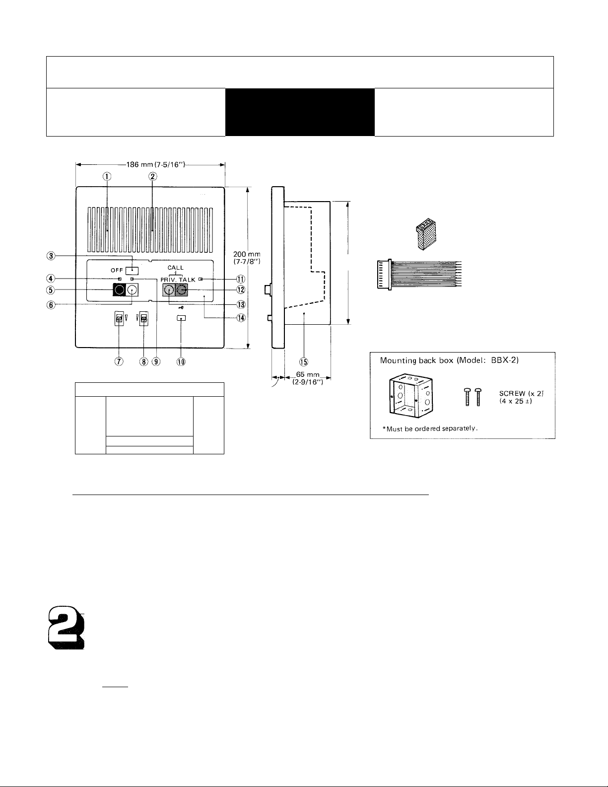
NAMES AND FUNCTIONS
Microphone
®
Speaker
@
Directory card OCCUPIED LED
®
Station selection indicator LED
OFF button PRIVACY button
Station selector button Panel
Communication volume control
Call tone volume control
Call annunciator LED
®
Door release button
TALK button
Mounting back box (Model: BBX-2)
SYSTEM FEATURES
1. Versatile communication system, Either All-master, Single-master or Intermixed System can be created.
2. Intermtxable masters and subs, either semi-flush mount (LAF-B) or desk/wall mount type (LAF).
3. Can receive All Call announcement and Background music.
4. Sub call-in annunciator LED stays lit for approx. 20 seconds.
5. During your communication, sub call-in can be signalled by soft tone.
6. Options; * * Door stations. * Door release, using RY-PA relay.
* Paging thru an 8-ohm horn with talkback.
1
Page 2
BEFORE YOU INSTALL AND OPERATE THE EQUIPMENT
— Prohibitions and precautions —
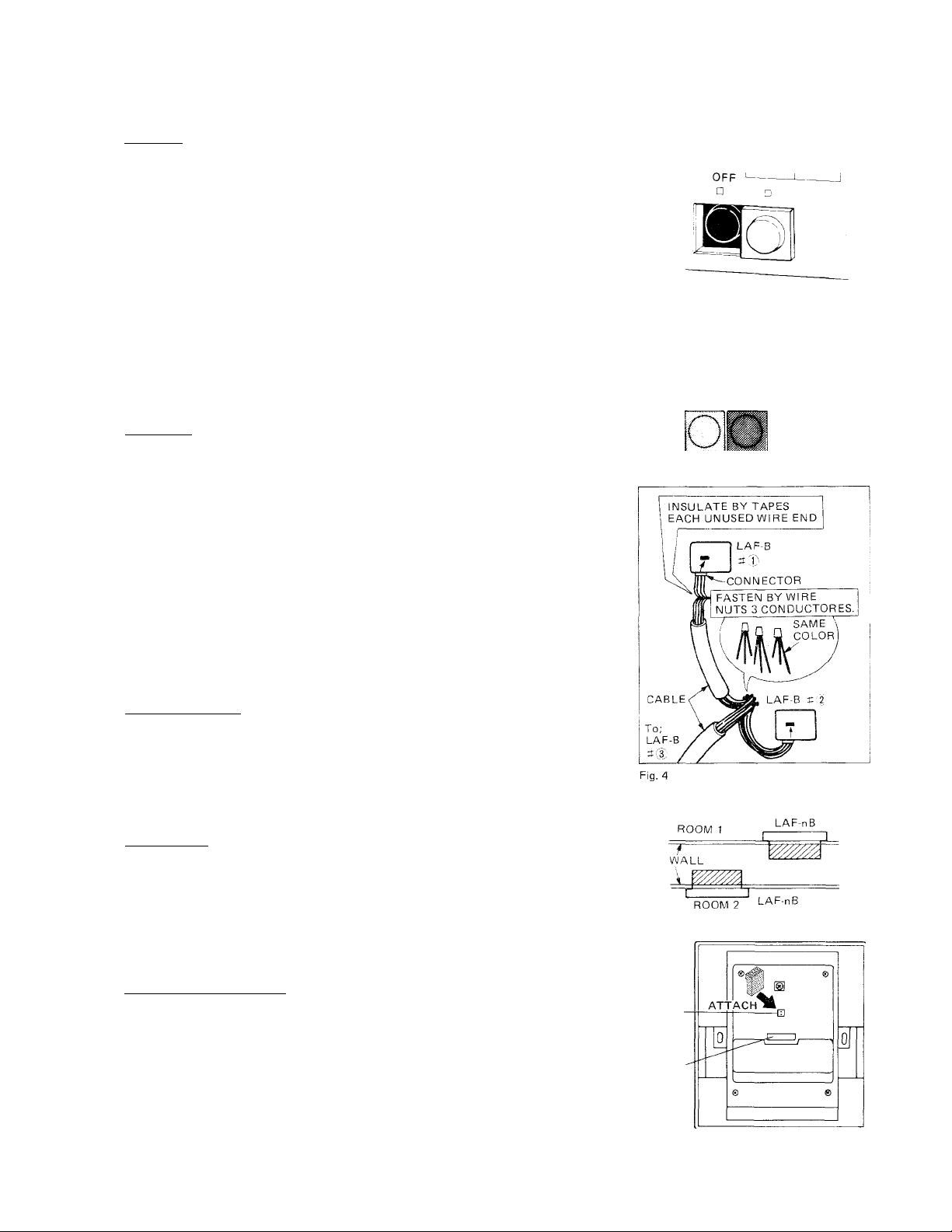
* Operation i Fig. 1
1. On all LAP master stations, except station initiating a call, OFF button MUST
BE DEPRESSED and LOCKED DOWN, or system will not work. The illuminated
LED above OFF button indicates you forgot to depress OFF button, if not in
use. (See Fig. 1)
2. The illuminated OCCUPIED LED indicates the other station is using the system.
While this OCCUPIED LED is lit, (See Fig. 2)
(1) Do not depress any selector button, or an electronic feedback will occur at
initiating and receiving stations.
So, when you receive calls from another master and a sub at the same time. Fig. 2
REPLY FIRST TO THE MASTER and, after the OCCUPIED LED goes
out, depress selector button of the calling sub and communicate.
(2) Can not make All Call announcement.
3. When a sub station calls during Background music distribution, the call tone
will come out through all LAF station speakers, and call-in annunciator LED
stays lit for approximately 20 seconds on the called master station.
* Installation;
1. DO NOT CONNECT ANY TERMINAL ON ANY UNIT TO AC POWER LINES.
2. Maintain at least 50 cm (20") distance from any AC wiring. Shielded cable
should be used to reduce the possibility of AC inductance.
3. Be sure not to plug power supply into AC receptacle until you complete wiring
connections, and unplug before opening it.
4. Lay out your system in advance. Determine the exact location of each station.
-Assign station number and make a sketch showing the number of wires and
color codes from one station to another. Begin your installation with master
station No. 1. Upon installing second master station, we recommend a test be
made for all functions, calling and talking between each station.
After connecting and testing all the masters, begin sub station installation.
5. Insulate by tape, etc. each unused connector wire end. If connector wire end
touches the other wires or back box it will cause damage to the units.
Installation location;
6. Select the installation locations that would not be exposed to temperature/
humidity extremes, water, oil, dust, iron dust, inflammable and chemical
products, etc.
7. To avoid feedback, DO NOT PLACE MASTER STATION AND ANOTHER
MASTER OR SUB STATIONS BACK TO BACK, OR ON A COMMON WALL
BETWEEN ROOMS. (See Fig. 4)
Unit selection;
8. When making an intermixed system, note in advance that master stations;
LAF-3A, LAF-5, LAF-10 console type have no button for All Call nor door
release. LAF-IB and LAF-3B have only door release button. If such functions
are required at console type station, please use LAF-1 OS.
9. If any LAF-B station: LAF-1B/3B/7B/10B (Type A) is intermixed with existing Fig. 5
models: LAF-3A/5/10/10S/10B, install a supplied shorting chip on back of all
the LAF-B units. (See Fig. 5)
Adaptor installation location
10. Locate PS-12A (or PS-1 2C) power supply near center of the system.
* Maintenance
1. Clean your equipment with a soft cloth dampened with neutral
household cleanser. Never use thinner or benzine, etc.
2-PIN
CONNECTOR
CONNECTOR
FOR STATION
WIRING
STANDBY
The illuminated red LED
above right of TALK button
indicates system is used now.
PRIV. TALK
Fig. 3
CALL
r
OCCUPIED
NEVER
\W/
LAF-1B BACK VIEW
- 2
Page 3

’‘Volume adjustment;
LAF-B unit has preset volume control, allowing you to lower the maximum level
of communication. On back of LAF-IB unit, using a phUip screwdriver, turn
the volume counter-clockwise to achieve the desired level.
On front panel, LAF-B unit has two volume controls for communication and call
tone, each adjustable to three levels as desired.
ACTUAL TERMINAL LOCATION
TO LOWER MAX.
COMMUNICATION VOLUME
LOWER
1°
LAF-IB BACK VIEW
VOLUME
CONTROL
10-PIN CONNECTOR
(male)
LAF-IB BACK VIEW
10-PlN CONNECTOR WITH 8
WIRES OF APPROX. 22 CM (8-5/8")
PIN/WIRE COLOR CODE
IDENTIFICATION
+ Red
— Black
1 Brown
C Yellow
E Green
Y Blue
R Purple
L Gray
01 : for power supply
[±]
m
[s
[0
[Y]
E
: for connecting station unit
: for receiving a call and BGM
: for common communication
for sub’s call-in tone during
' communication
: for occupied LED
: for door release
INSTALLATION
3
Semi-flush mounting to wall (in new construction);
(1)
For new constmction, use a mounting back
box (Model BBX-2).
1.
Install the back box in the wall.
Remove a panel on LAF-IB front case.
2.
Mount LAF-IB unit to the back box with
3.
tv/o screws (supplied).
Reattach the panel.
4.
Semi-flush mounting to an existing wall;
(2)
1.
To install LAF-IB unit to an existing wall,
cut and open a hole of H: 160 mm (65/16”) X W: 116 mm (4-9/16"), securing
depth of more than 50 mm (1-15/16").
Remove a plate on LAF-IB front case.
Mount LAF-IB unit directly to wall with
two wood screws (supplied).
Reattach the panel.
To remove a panel
LAF-1B
FRONT CASE
^aS'5<'
mm
1/16")
PUT UNDER RIB to attach
Page 4

SPECIFICATIONS
a
* Power source:
* Current consumption;
*Communicaticin:
* Communication output:
* Communication network:
*Calling:
*Ta]k channel:
*Wiring:
DC 12V. Use PS-12A (or PS-12C in North America) power supply.
350 mA maximum.
Press-to-talk, release-to-listen at calling master.
800 mV maximum at 20 ohm.
Either All-Master, Single-Master or Intermixed System can be created.
Electronic tone and an illuminated LED (staying lit for approx. 20 seconds), when called by sub
(at master)
Electronic tone or voice direct when called by master (at master)
Electronic tone or voice direct when called by master (at sub).
1 talk channel.
(D Between master stations;
•"Wiring distance;
•"Dimensions:
Recessed:
"•"Weight:
"•" RY-PA relay contact
capacity:
Between masters
For communication only 5 common -t 1 individual
For communication and
BGM reception
For door release
For all functions as above
(2) Between sub station; 3 wires for each sub station.
Between master and farthest master/sub station;
AWG 24 AWG
Distance
Diameter
Distance
H
200 mm X w
7-7/8"
(H
152 mm
H
6"
(H
Approximately 460 g (1.01 lbs.).
AC llOV, lA.
DC 24V, lA.
400' 650'
0.5 mm
120 m
186 mm
X w 7-5/16"
112 mm
X w
X w 4-7/16"
5 common + 1 individual
Plus 1 common (additional)
6 common + 1 individual
22 AWG ,
0.65 mm
200 m
D : 15 mm
X
D ; 9/16")
X
X D ; 50 mm
D : 1-15/16")
X
20 AWG 18 AWG
1,000' 1,600'
0.8 mm
300 m 480 m
Between masters &
BG-IA/IB
—
4 common + 1 individual
—
4 common + 1 individual
1.0 mm
- 4-
IN I tHUUM SYS I hMS
® AlPHONE
HOME, BUSINESS, INDUSTRY
Printed in Japan (E)
 Loading...