

Page 1
#91173 0406
Access Control Keypad for MK-DV, JB-DV
- INSTRUCTIONS -
The KVI is a surface mount electronic access control keypad for use with Aiphone’s MK-DV or JB-DV video door
station. Designed with the same aesthetic look as the door station, this keypad allows access for authorized
personnel with up to 100 unique PIN codes. Use the KVI for residential or commercial applications along with the
Aiphone MK or JB Video Entry system for a complete audio, video, and access control package.
NAMES & FEATURES
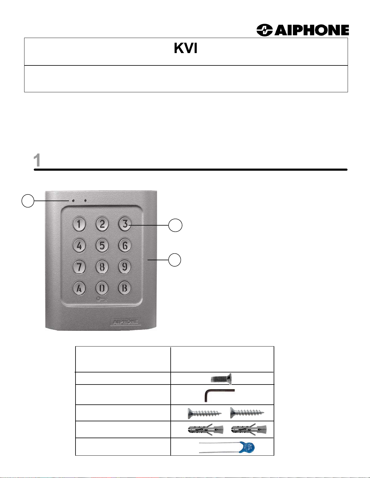
KVI Keypad
NAMES & FUNCTIONS:
1
1. Operation LEDs
2. Digital keys
3. Zinc diecast case
2
MOUNTING HARDWARE:
Qty Description
1 TORX M4x10 screw
1 TORX T20 Tool
2 M4x30 screw
FEATURES:
· Streamline surface mount design
3
· Compatible with MK-DV or JB-DV
· Can be used as a standalone access control keypad
· 12-digit backlit panel
· Programmable with 100 unit pin codes (4 or 5 digits)
· One programmable master code, 4 or 5-digits
· 2 request-to-exit inputs
· 2 Relay outputs: N/O & N/C
· Red LED lights when relay #1 is activated
· Green LED lights when relay #2 is activated
2 S5 plastic anchor
1 05D 680K varistor
Pg. 1
Page 2
INSTALLATION & MOUNTING
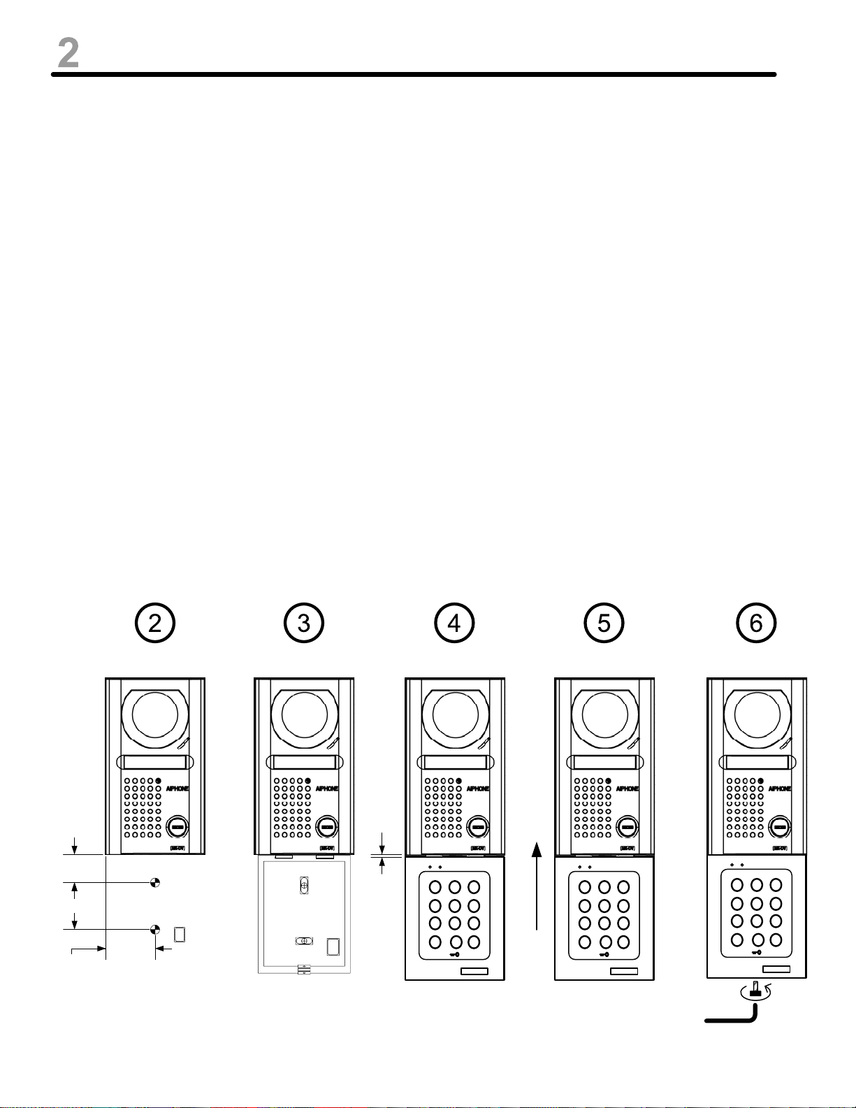
Mounting Instructions:
1. After the MK-DV or JB-DV video door station has been installed, position KVI
mounting bracket underneath and mark mounting hole positions. (Use exact
dimension template on page 3 for positioning.) Top KVI bracket mounting hole
should be 1-3/16" below the bottom of the video door station.
2. Drill two mounting holes, 3/16" diameter, 1-3/8" depth (Ø5mm, depth 35mm) and an
access hole for the multi-conductor connecting wire. (See illustration on page 3.)
3. Install the plastic anchors in mounting holes.
Mount the KVI back plate with the M4x30 screws.
4. Insert the KVI keypad cable in the wiring access hole (lower right corner).
Place the KVI keypad against the back plate, leaving a gap of 1/8" to 1/4"
between the bottom of the video door station and the top of the keypad.
5. Slide the keypad up (matching up to the bottom of the video door station).
The keypad will slide into the clips at the top of the bracket.
6. Make sure the keypad covers the back plate (the bottom of the keypad seated
properly on the back plate). Install the M4-10 screw in the bottom of the
keypad, using the Allen key to tighten the screw (Torx T20).
1/8" to
3/16"
1 3/16"
2 3/16"
1 15/16"
1 2 3
4 5 6
7 8
A
B90
AIPHONE
1 2 3
4 5 6
7 8
A
B90
AIPHONE
1 2 3
4 5 6
7 8
A
B90
AIPHONE
Pg. 2
Page 3
INSTALLATION & MOUNTING
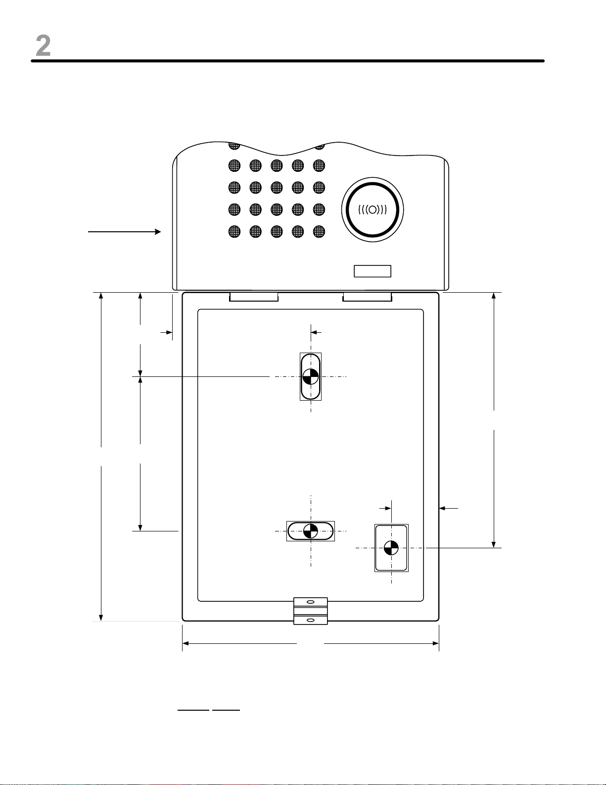
MOUNTING TEMPLATE:
MK-DV or
JB-DV
4 5/8"
(117mm)
1 3/16"
(30mm)
2 3/16"
(55mm)
1 15/16"
(49mm)
Mounting hole
3 9/16"
(91mm)
KVI BACK PLATE
11/16"
(17mm)
Mounting hole
Wiring hole
3 5/8"
(91mm)
NOTE: This diagram is actual scale, and can be copied for use as a template for mounting the KVI.
Pg. 3
Page 4

WIRING DIAGRAM
12-24V AC/DC
Power in Black
Power in Red
KVI KEYPAD
Strike
power
# 1
varistor
NOTE: Either contact can
operate an electric strike or
magnetic lock (connected with
either the Normally Open or
Normally Closed output).
N/O Contact #1 Orange
Common Contact. #1 Pink
N/C Contact #1 Brown
Request-To-Exit
Switch #1
Request-To-Exit #1 Green
R-T-E Common Yellow
Request-To-Exit #2 Lt. Blue
Lt. Green
Mag Lock
#2
Pg. 4
power
varistor
Request-To-Exit
Switch #2
N/C Contact #2 Dark Blue
Common Contact #2 Purple
N/O Contact #2 Gray
Optional contact for
“Request-to-Enter”
function
(See page 5)
Page 5

SETTINGS
DEFAULT VALUES:
· Master code: 12345
· Pin Code length: 5 digits
· Timed relay output (Relay 1 and 2): 1 second
· Backlit time per use: 10 seconds
· Key-in keypad time: 120 seconds
· No Pin codes pre-programmed
PIN CODE LENGTH:
· The Master code and the Pin codes must have the same code length.
· The Master code and the Pin codes can be set to either a 4 or 5 digit code.
· All the digit keys on the keypad can be used in a Pin code (0 to 9, A and B).
· The master code cannot be used as a Pin code.
· Codes 0000 and 00000 are strictly used to delete a Pin code, and cannot be set as a Pin code.
· Each key-in on the keypad lights the red LED.
REQUEST TO EXIT:
· The request-to-exit input 1 (green & yellow wires) activates relay 1.
· The request-to-exit input 2 (blue & yellow wires) activates relay 2.
REQUEST TO ENTER:
A separate timer or switch may be connected across the light green and yellow wires to allow the 0
button to function as a request-to-enter button. If the timer or switch contact is closed, the 0 button
will function as a request-to-enter button. If the contact is open, the 0 button will function normally.
SETTING THE CODE LENGTH AND THE MASTER CODE:
1. Enter the master code twice (for the first use, the master code default value is “12345”). The red
LED will light up to confirm entry into programming mode.
NOTE: If you change the code length to a 4 digit from the default 5 digit, you must change
the master code to a 4 digit code prior to exiting programming or you will not be able to reenter the program mode. If this happens, a manual reset of the system would then be
required. Refer to page 6 for reset procedure.
2. Enter “A3” to set the code length (both pin code and master code). The green LED will light up for
1 second. Enter “4” for a 4-digit code length or “5” for a 5-digit code length. The green LED will
light up to confirm that the code length has been accepted.
3. Enter “A4” to modify the master code. The green LED will light up for 1 second. Enter the 4 or 5digit master code. The green LED will light up for 1 second to confirm that the new master code
has been accepted.
4. Press “B” to exit programming mode. The red LED will turn off to confirm that the unit is no longer
in programming mode.
NOTE: When the red LED flashes 4 times, it indicates a data computing error.
Pg. 5
Page 6

SETTINGS (Continued)
SETTING THE PIN CODES:
Group 1: User numbers 00 to 59 activates Relay 1.
Group 2: User numbers 60 to 99 activates Relay 2.
1. Enter the master code twice (for the first use, the master code default value is 12345). The red LED will light up
to confirm entry into programming mode.
2. Enter the user number (from 0 to 99). If the user number is free, the green LED lights up and turns off right
away. If the user number has been previously programmed, the red LED will turn off and come on again
immediately.
3. Enter the 4 or 5-digit Pin code. The green LED lights up for 1 second to confirm that the new Pin code has
been accepted.
NOTES:
* If the new Pin code entered is already programmed or is the same as the master code, the red LED flashes
4 times to indicate a data computing error.
* The master code cannot be used as a Pin code. Codes 0000 and 00000 are used strictly to delete a Pin
code and cannot be used as a Pin code.
4. Press “B” to exit programming mode. The red LED will turn off to confirm that the unit is no longer in
programming mode.
SETTING TIME DELAYS:
1. Enter the master code twice (Default setting of the master code is 12345). The red LED will light up to confirm
entry into programming mode.
2. Enter “A0” to program the keypad’s backlight time. The green LED will light up for 1 second. Enter the time in
seconds (i.e. “10” for 10 seconds to “99” for 99 seconds). The green LED will light up for 1 second to confirm that
the data was accepted.
3. Enter “A1” to program the time delay for relay 1. The green LED will light up for 1 second. Enter the time in
seconds (i.e. “01” for 1 second up to “99” for 99 seconds). To program a latched contact output, enter “00”
(Contact will remain latched upon code entry until the next accepted code is entered). The green LED will light
up for 1 second to confirm that the data was accepted.
4. Enter “A2” to program the timed delay for relay 2. The green LED will light up for 1 second. Enter the time in
seconds (i.e. “01" for 1 second up to “99” for 99 seconds). To program a latched contact output, enter “00”
(Contact will remain latched upon code entry until the next accepted code is entered). The green LED will light
up for 1 second to confirm that the data was accepted.
5. Press “B” to exit programming. The red LED will turn off to confirm that the unit is no longer in programming
mode.
When the Red LED flashes 4 times, a data computing error has occurred.
RESET:
1. Enter the master code twice (Default setting of the master code is 12345). The red LED will light up to confirm
entry into programming mode.
2. Enter “A5”. The green LED will light up for 1 second. Press “A B” to start the reset. The green LED will light up.
Wait until the green LED turns off (approximately 3 seconds). The master code will be reset to the factory default
value of 12345 and all the Pin codes will be deleted from the keypad.
3. Press “B” to exit from programming. The red LED will turn off to confirm that the unit is no longer in programming
mode.
OR
4. Turn the power off. Short the yellow and white wires together.
5. Turn the power back on. The green LED will light while the data is being reset. Separate the yellow and white
wires. The green LED will turn off when the reset function is completed. If the short is maintained between the
two wires, the green LED will stay lit.
Pg. 6
Page 7

PIN CODE CHART
Copy this chart and use as a master copy for the Pin Codes entered into the KVI keypad.
Master Code Master Code
• To select code length, enter “A3”. Green LED will light up for 1 second. Select desired digit length (4 or 5). Green LED
will light up to confirm that the change was accepted.
• To modify master code, enter “A4". Green LED will light up for 1 second. Enter new master code. The Green LED will
light up to confirm that the change was accepted.
00
01
02
03
04
05
06
07
08
09
10
25
26
27
28
29
30
31
32
33
34
35
50
51
52
53
54
55
56
57
58
59
60
Red LED
lights on
75
76
77
78
79
80
81
82
83
84
85
11
12
13
14
15
16
17
18
19
20
21
22
23
24
Keypad backlit time
A0
• Enter “A1” to program the time delay for relay 1. Green LED will light up for 1 second. Enter time in seconds (01-99).
To program a latched output, enter “00”. The green LED will light up for 1 second to confirm that the data has been accepted.
• Enter “A2" to program the time delay for relay 2 (same as above A1 above).
• Enter “A0” to program the keypad backlight time. Green LED will light up for 1 second. Enter time in seconds (10-99). The green
LED will light up for 1 second to confirm the data has been accepted.
36
37
38
39
40
41
42
43
44
45
46
47
48
49
Time delay relay 1
A1
61
62
63
64
65
66
67
68
69
70
71
72
73
74
86
87
88
89
90
91
92
93
94
95
96
97
98
99
Time delay relay 2
A2
Pg. 7
Page 8

SPECIFICATIONS
Input Voltage: 12 to 24V, AC or DC
Keypad: 12-digit backlit keypad
Outputs: 2 relays N/O & N/C, 6A at 250V
PIN Codes: 100 pin codes (4 or 5 digit pin codes programmable in two groups)
Master Code: 1 programmable master code, 4 or 5-digit
Inputs: 2 request-to-exit inputs
“0” key can be used as request-to-enter button, enabled with a
timer relay contact
Red LED: Programming indicator and relay 1 activation indicator
Green LED: Validation in programming mode and relay 2 activation indicator
Operating
temperature: -4°F to 158°F (-20°C to 70°C)
Cable Length: 9 feet
Dimensions: MK-DV/JB-DV –
4 ⅝”H x 3 ⅞”W x 1"D
KVI –
Wires: 13 total.
Power = Red, Black
Relay 1 = Orange, Brown, Pink
Relay 2 = Dark Blue, Purple, Gray
R-T-E = Green, Lt. Blue, Yellow
Timer for R-T-E = Lt. Green, Yellow
Reset = White, Yellow
6 ¾”H x 3 ⅞”W x 1"D
6 ¾”
11 ½”
3 ⅞”
PROGRAM CODES:
A0: Set keypad backlit time
A1: Set timed output for relay 1
A2: Set timed output for relay 2
A3: Set PIN code length (4 or 5 digits)
A4: Modify Master Code
4 ⅝”
1 2 3
4 5 6
7 8
A
B90
AIPHONE
A5: Enter Reset Mode
WARRANTY
Aiphone warrants its products to be free from defects in material and workmanship under normal use and
service for a period of one year after delivery to the ultimate user. We will repair free of charge or replace at no charge
Aiphone product, that upon examination by an Aiphone Repair Technician is proven defective and under warranty.
Aiphone reserves the right to make the final decision whether there is a defect in materials and/or workmanship; and
whether or not the product is within the warranty.
This warranty covers bench repairs by the Aiphone Service Department only, and does not extend to units that
have been repaired or altered outside of the factory. Aiphone is not responsible for any costs incurred involving on-site
service calls.
This warranty shall not apply to any Aiphone product that has been subjected to misuse, neglect, accident,
power surge, or used in violation of instructions furnished.
Aiphone Communication Systems
1700 130th Ave. N.E.
Bellevue, WA 98005
(425) 455-0510
FAX (425) 455-0071
Toll Free Technical Support
1-800-692-0200
TOLL FREE FAX LINE:
1-800-832-3765
E-Mail: tech-serv@aiphone.com
KVI Instr. #91173
Pg. 8
0406JDJS
 Loading...