

Page 1
GT SYSTEM
Standard & Expanded System
Quick Start Installation Guide
ATTENTION:
This is an abbreviated Installation Manual, addressing wiring and programming of the GT Series. The
complete GT Series Installation Manual is located on the CD supplied with the GT-BC Bus Control
Unit. Access the PDF fi le from the CD and print the entire manual if a hard copy is needed. If installing a digital
entry system, the program for loading names and numbers for each residence is also located on the CD.
Page 2
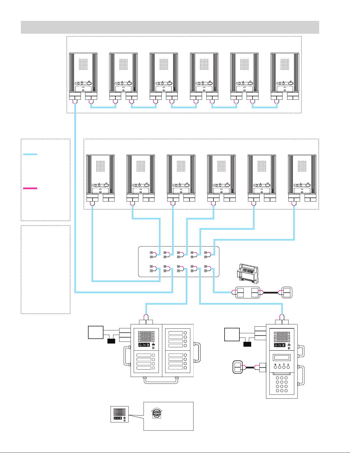
SYSTEM WIRING: AUDIO ONLY DIRECT SELECT & ENTRANCE STATIONS
WIRE TYPE
20AWG (0.8mm)
2 Cond.
Solid Non Shielded
PE Insulated
18AWG (1.0mm)
2 Cond.
Solid Non Shielded
PE Insulated
: Audio line
: Video line
Loop Wiring Method
R1 R2INR1 R2
OUT
R1 R2INR1 R2
OUT
R1 R2INR1 R2
OUT
R1 R2INR1 R2
R1 R2INR1 R2
OUT
Max. of 25 stations per loop / trunk (Max of 50 stations when using GT-1D)
R1 R2INR1 R2
OUT
Max. wire distance from distribution point to any residence is 980’. (300 m)
Max. cumulative wire distance is 8200’. (2500 m)
Refer to page 9 of the GT Series Installation Manual for complete wire distance information.
Homerun Wiring Method
R1 R2INR1 R2
OUT
R1 R2INR1 R2
OUT
R1 R2INR1 R2
OUT
R1 R2INR1 R2
OUT
R1 R2INR1 R2
OUT
OUT
R1 R2INR1 R2
OUT
POWER
PS24
PS-2420UL
PS-2420
PS-2420S
PS-2420BF
PS-2420D
PT
Power Transformer
(Use proper power
for the Strike or Mag
Lock being used).
*
Distribution Point:
NOT provided by Aiphone
except for Europe. This
can be any device that
parallels or commons
the R1 / R2 connection.
(Terminal strip, punch
down block, wire nuts, etc.)
Residential/tenant
stations shown are the
GT-1A. The GT-1D
stations can also be used
and are wired in the same
manner.
Door
Strike
PT
CN2
CN1
GT-DA-L/GT-DA
ELM
ELC
ELB
*DP
R1
R2
R1
R2
CN2
20
0.5 M
103
0.5 to 20: 0.5 to 20 seconds
M: While door release button is pressed
CN1
CN1
CN2
ELM = Make (N/O)
ELC = Common
ELB = Break (N/C)
Mag
Lock
PS24
GT-BC
R1
R2
PT
+
-
+
-
ELM
ELC
ELB
PS24
+
-
R1 R2R1 R2
CN2
CN1
+
-
CN3
CN100
2
Page 3
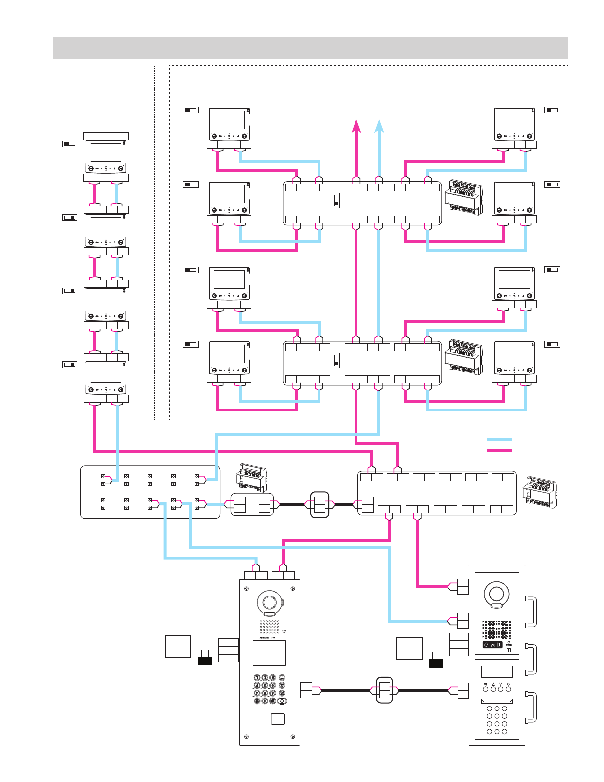
SYSTEM WIRING: AUDIO / VIDEO ALL-IN-ONE & ENTRANCE STATIONS
Loop Wiring Method Homerun Wiring Method
Max. of 25 stations per
loop. SW1 switch must
be set to A on last station
in the wire loop.
AB
SW1
Max. of 6 GT-4Zs per loop. SW1 switch must be set
to A on last GT-4Z in the wire loop. Each residential/
tenant station homeruns to a GT-4Z and its SW1
switch must be set to A.
AB
SW1
B1 B2R1 R2
AB
SW1
B1 B2R1 R2
B1 B2R1 R2
AB
SW1
B1 B2R1 R2
B1 B2R1 R2
AB
SW1
B1 B2R1 R2
B1 B2R1 R2
AB
SW1
B1 B2R1 R2
OUT
IN
OUT
IN
OUT
IN
OUT
IN
IN
B1 B2R1 R2
AB
SW1
IN
AB
SW1
IN
B1 B2R1 R2
AB
SW1
IN
B1 B2R1 R2
B1 B2R1 R2 B1 B2R1 R2 B1 B2R1 R2
OUT (3) OUT (4)
OUT (1) OUT (2)
B1 B2R1 R2 B1 B2R1 R2
B1 B2R1 R2 B1 B2R1 R2 B1 B2R1 R2
OUT (3) OUT (4)
OUT (1) OUT (2)
B1 B2R1 R2 B1 B2R1 R2
SW1
SW1
A
B
A
B
LINE OUT
IN
R1 R2B1 B2
LINE OUT
IN
R1 R2B1 B2
GT-4Z
GT-4Z
B1 B2R1 R2
B1 B2R1 R2B1 B2R1 R2
B1 B2R1 R2
B1 B2R1 R2
IN
AB
SW1
IN
AB
SW1
IN
AB
SW1
IN
*DP
*
Distribution Point:
NOT provided by
R1
R2
R1
R2
Aiphone except for
Europe. This can be any
device that parallels or
commons the R1 / R2
connection. (Terminal
strip, punch down block,
wire nuts, etc.)
Residential/tenant
stations shown are the
GT-1C7(-L). The GT2C(-L) or GT-1M3(-L)
can be used and are
wired in the same
manner.
Note: GT-2C(-L)
requires a separate PS24 power supply.
Door
Strike
B1 B2 B1 B2 B1 B2 B1 B2 B1 B2 B1 B2
+
A1 A2 A1 A2 A1 A2 A1 A2 A1 A2
-
R1
R2
PS24
+
-
+
-
GT-BC
A1 A2R1 R2
ELM
ELC
ELB
PT
+
-
Mag
Lock
+
-
A1
A2
R1
R2
ELM
ELC
ELB
PT
+
-
: Audio line
: Video line
GT-VBC
CN3
CN1
CN2
CN1
CN3
PS24
CN100
3
Page 4
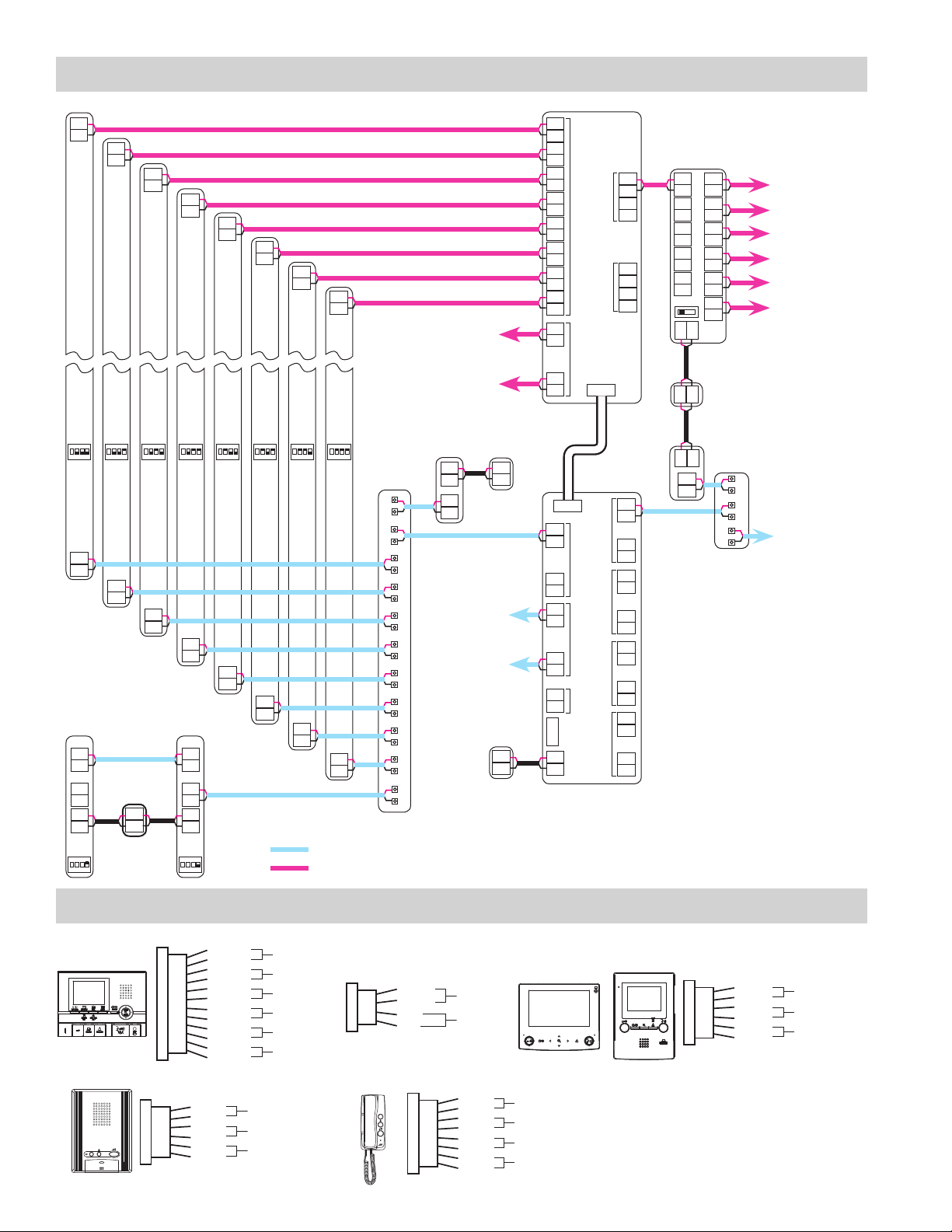
SYSTEM WIRING: EXPANDED SYSTEM
A1
A2
A1
A2
A1
A2
A1
A2
A1
A2
A1
A2
A1
A2
A1
A2
GT-VAAGT-DA
#1 #5#3 #7#2 #6#4 #8
ON
4
123
R1
R2
GT-MK
IN
R1
R2
OUT
R1
R2
+
-
#2
ON
4
123
ON
123
R1
R2
4
+
-
PS24
ON
123
R1
R2
ON
4
123
R1
R2
GT-MK
OUT
R1
R2
R1
R2
#1
ON
123
ON
ON
4
4
123
R1
R2
IN
+
-
4
4
123
R1
R2
ON
ON
4
123
123
R1
R2
R1
R2
: Audio line
: Video line
4
Connection
for video
entrance
modules 9-16
*DP
Connection
for audio
entrance
modules 9-16
GT-BC
+
-
R1
R2
{
PS24
{
PS24
GT-VBX
A1
A2
A1
A2
A1
A2
COMMON 1
A1
A2
A1
A2
A1
A2
A1
A2
A1
A2
A1
COMMON 2
A2
~
A1
A2
+
-
CN1
R1
COMMON 1
R2
~
R1
R2
R1
COMMON 2
R2
~
R1
R2
GTW-LC
R1
R2
USB
+
-
+
-
CN2
B1
B2
B1
SUB 1
B2
B1
B2
B1
SUB 2
B2
GT-BC
R1
R2
~
SUB 1A
R1
R2
R1
R2
~
SUB 1B
R1
R2
R1
R2
~
SUB 2A
R1
R2
R1
R2
~
SUB 2B
R1
R2
GT-BCX
GT-VBC
B1
A1
A2
A1
A2
A1
A2
A1
A2
A1
A2
EXP STD
+
+
+
R1
R2
B2
B1
B2
B1
B2
B1
B2
B1
B2
B1
B2
-
-
PS24
-
*DP
Video outputs
to residential/
tenant stations
and / or GT-4Z
units. Max. of
25 residences
per trunk
and 125 total
residences per
GT-VBC.
Audio output
to residential/
tenant stations
and / or GT-4Z
units. Max. of
25 residences
per trunk
and 125 total
residences per
GT-BC.
*Distribution Point:
NOT provided by Aiphone
except for Europe. This can
be any device that parallels
or commons the R1 / R2
connection. (Terminal strip,
punch down block, wire
nuts, etc.)
OPTION CONNECTOR: RESIDENTIAL/TENANT STATIONS
GT-2C-L
GT-2C
GT-1A
4
12-pin option connector
(Brown)
K
KE
RY
RY
SW
SW
S1
S1E
S2
S2E
S3
S3E
(Red)
(Blue)
(White)
(Gray)
(Black)
(Orange)
(Black)
(Yellow)
(Black)
(Purple)
(Black)
Emergency alarm
Call transfer
Option contact output
Security/Utility input 1
Security/Utility input 2
Security/Utility input 3
Option connector
(Yellow)
DC
DC
RY
RY
SW
SW
Doctor call (Automatic entry)
(Orange)
(Blue)
Call transfer
(White)
(Gray)
Option contact output
(Black)
4-pin option connector
(not included)
V+
(Brown)
Video out
(Red)
V
-
GT-1D
(Orange)
(Yellow)
Display transfer
Option connector
K
KE
C
CE
RY
RY
SW
SW
GT-1C7-L
GT-1C7
(Brown)
Emergency alarm (JP1 is cut during use.)
(Red)
(Orange)
Doorbell
(Yellow)
(Blue)
Call transfer
(White)
(Gray)
Option contact output
(Black)
GT-1M3-L
GT-1M3
Option connector
(Yellow)
DC
DC
RYC
RYC
SW
SW
Doctor call (Automatic entry)
(Orange)
(Blue)
Call transfer
(White)
(Gray)
Option contact output
(Black)
Page 5
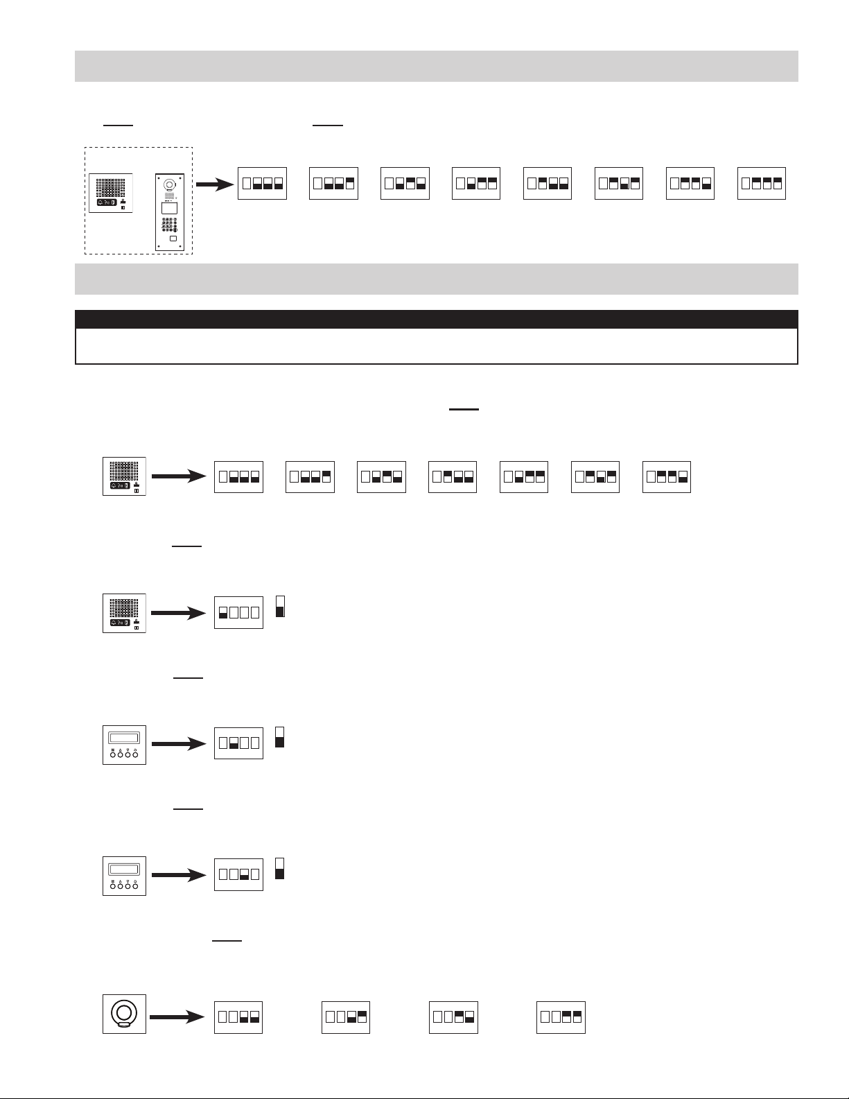
DIP SWITCH SETTINGS: ENTRANCE STATION (REQUIRED)
Entrance ID Setting:
Use SW2 on the GT-DA(-L) module or SW1 on the GT-DM(V)A entrance station to set the ID settings for each entry
panel. Only switches 2, 3, & 4 are used for this setting.
GT-DA-L
GT-DA
GT-DMVA
GT-DMA
#1 #5#3 #7#2 #6#4 #8
ON
123
ON
4
123
ON
4
123
ON
4
123
ON
4
123
ON
4
123
ON
4
123
ON
4
123
4
DIP SWITCH SETTINGS: ENTRANCE STATION (OPTIONAL)
NOTE:
When using the GT-DM(V)A, the settings listed below will be done via the 10 key / display while in programming
mode. Refer to the GT Series Installation Manual (pages 43 - 49) for set-up instructions.
Guidance Language Selection:
The guidance is set to off (No Guidance) when shipped. Use SW3 on the GT-DA(-L) module to set the appropriate
language. Only switches 2, 3, & 4 are used for this setting.
GT-DA-L
GT-DA
Entrance Monitor Setting:
Use switch 1 of SW2 on the GT-DA(-L) module to enable / disable entrance monitoring. Initial setting is “Monitoring not
possible.” Enabling will allow residences (video residences only) to monitor the entrance area.
GT-DA-L
GT-DA
No Guidance English German DutchFrench Spanish Italian
ON
123
ON
4
123
ON
4
123
ON
4
123
ON
4
123
ON
4
123
ON
4
123
(initial setting)
ON
123
Monitoring possible
Monitoring not possible
4
1
4
Room Number Display:
Use switch 2 of SW1 on the GT-NS(-V) module to choose between displaying only resident name or displaying room
number also. Initial setting is “Display room number also.”
GT-NS-V
GT-NS
ON
123
Display only resident name
Display room number also
4
2
Message Setting:
Use switch 3 of SW1 on the GT-NS(-V) module to select between greeting message or operation message on the
display. Initial setting is “Greeting Message.”
GT-NS-V
GT-NS
ON
123
Operation Message
Greeting Message
4
3
Call Screen Setting:
Use switches 3 & 4 of SW1 on the GT-VAA module to set the camera view. The initial setting is Zoom.
Zoom 3s>>Wide: Image starts zoomed and after 3 seconds goes wide.
Wide 3s>>Zoom: Image starts wide and after 3 seconds zooms.
GT-VAA
ZOOM WIDE ZOOM 3s>>WIDE WIDE 3s>>ZOOM
ON
123
ON
4
123
4
ON
123
ON
4
123
(initial setting)
4
5
Page 6

PROGRAMMING: INPUT RESIDENT INFORMATION
NOTE:
The GT digital panel, GT-DM(V)A, and GT-MK must be programmed with the resident information before residential/
tenant stations can be addressed. The resident information can be entered using the 10 key or by using the software
supplied on the CD.
Entering Resident Info Using 10 key
Step 1: On the 10 key, enter # plus the ID code (*1111). Re-enter ID code (*1111).
Step 2: Scroll to
Step 3:
Step 4: The room number entered will appear on screen along with a space for the Resident Name. Use the
Step 5: Repeat steps 3 & 4 for remaining residents.
Step 6: Press “X” to return to main menu. Scroll to
ROOM # will display on the screen. Enter the desired room number (ie: 101, 102, 103, etc.) and press Bell button .
10 key and Arrow buttons to key in the resident name (if desired) and press Bell button when fi nished.
Entering Resident Info Using Software
Step 1: Using the CD supplied with the GT-BC, install the GT software and USB cable driver on a PC running
Windows® XP, Windows Vista®, Windows® 7, or Windows® 8.
Step 2: Open GT software, click
Step 3: Select
Step 4: Enter a Room # and Name (if desired) for each resident.
Step 5: Connect the USB cable to the PC and to the GT device being programmed. Ensure that the GT device
being programmed is powered.
Step 6: Refer to the PC’s device manager to determine which COM Port is being used for the cable driver.
Step 7: Select
Select the COM Port that was verifi ed in Step 6.
Step 8: Select
(Export sends data to the entrance station. Import pulls data from the entrance station.)
Step 9: A new window will open asking, “Do you want to overwrite the information?” Select
Step 10: Enter ID code (initial setting is *1111) and click
Data will be transferred.
RESIDENT INFO.
Resident
Connection
Connection
tab.
and press Bell button .
QUIT
GT System Mode
COM Port
Export
from the menu bar.
.
from the menu bar to see the available COM Ports on the PC.
and press “X” again to exit programming.
OK
.
Yes
.
PROGRAMMING: ADDRESSING RESIDENCES VIA HAND-SHAKE METHOD
Direct Select / Push Button Entrance Station Addressing
Step 1: Remove front panel from entrance station.
Step 2: To enter programming mode, use a small screwdriver to push and release button under the
rubber cap on front of speaker module (GT-DA(-L)). The amber LED will begin blinking, then
remain lit. Once lit, the entry panel is in programming mode.
Step 3: At residential/tenant station, push and release the TALK button to establish communication
with the entrance station in programming mode.
Step 4: Push and release the desired Call Button on the entrance station to assign the button to the
residential/tenant station that is active. A blip tone will be heard.
Do not press and hold the Call Button as doing so will clear the memory for this button.
Step 5:
Step 6: Repeat steps 3-5 for remaining residential/tenant stations.
Step 7: To exit programming, push the button under the rubber cap on the GT-DA(-L) module again
6
Turn off residential/tenant station (GT-1A, GT-1C7, GT-1M3: Push TALK again/ GT-2C(-L): Push OFF).
and the amber LED will turn off. The system is now ready for use.
Page 7
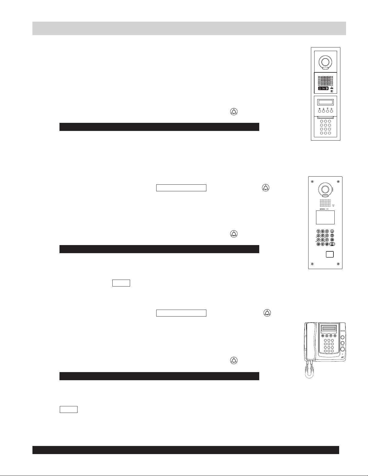
PROGRAMMING: ADDRESSING RESIDENCES VIA HAND-SHAKE METHOD (continued)
GT Entrance Station Addressing
Step 1: Remove front panel from entrance station.
Step 2: To enter programming, use a small screwdriver to push and release button under the rubber cap
on front of speaker module (GT-DA(-L)). The amber LED will begin blinking, then remain lit. Once
lit, the entrance station is in programming mode. The LCD will show “CONNECTING” while in
programming mode.
Step 3: At residential/tenant station, push and release the TALK button to establish communication with
the entrance station in programming mode.
Step 4: Scroll to the station number to be programmed or manually dial the number. When the residential/
tenant station number is displayed, push and release the Bell button
the residential/tenant station that is active. A blip tone will be heard.
Do not press and hold the Bell button as doing so will clear the memory for this address.
Step 5:
Step 6: Repeat steps 3-5 for remaining residential/tenant stations.
Step 7: To exit programming, push the button under the rubber cap on the GT-DA(-L) module again and
Turn off residential/tenant station (GT-1A, GT-1C7(-L), GT-1M3(-L): Push TALK again/ GT-2C(-L): Push OFF).
the amber LED will turn off. The system is now ready for use.
GT-DM(V)A Entrance Station Addressing
Step 1:
Step 2: Use the up / down arrows and scroll to
Step 3: At residential/tenant station, push and release the TALK button to establish communication with
Step 4: Scroll to the station number to be programmed or manually dial the number. When the residential/
Step 5:
Step 6: Repeat steps 3-5 for the remaining residential/tenant stations.
Step 7: To exit programming, press the “X” button on the panel to return to the main menu (the amber LED
While in standby mode, enter # plus ID code (initial setting is *1111). Re-enter ID code (initial setting is
PROGRAMMING
programming mode. The amber LED will begin blinking, then remain lit. Once lit, the entry panel is
in programming mode. The LCD will show “CONNECTING” while in programming mode.
the entrance station in programming mode.
tenant station number is displayed, push and release the Bell button to assign the address to
the residential/tenant station that is active. A blip tone will be heard.
Do not press and hold the Bell button as doing so will clear the memory for this address.
Turn off residential/tenant station (GT-1A, GT-1C7(-L), GT-1M3(-L): Push TALK again/ GT-2C(-L): Push OFF).
will turn off). Scroll to
QUIT
and press the “X” button again. The system is now ready for use.
. Push the Bell button to enter
to assign the address to
1111).
*
GT-MK Security Guard Addressing
Step 1:
Step 2: Use the up / down arrows and scroll to
Step 3: Pick up the handset on the GT-MK and leave off hook.
Step 4: At residential/tenant station, push and release the TALK button to establish communication with
Step 5: Scroll to the station number to be programmed or manually dial the number. When the residential/
Step 6:
Step 7: Repeat steps 4-6 for the remaining residential/tenant stations.
Step 8: To exit programming, press the “X” button on the GT-MK to return to the main menu. Scroll to
While in standby mode, enter # plus ID code (initial setting is *1111). Re-enter ID code (initial setting is
PROGRAMMING
programming mode. The LCD will show “CONNECTING” while in programming mode.
the GT-MK in programming mode.
tenant station number is displayed, push and release the Bell button
the residential/tenant station that is active. A blip tone will be heard from the GT-MK handset.
Do not press and hold the Bell button as doing so will clear the memory for this address.
Turn off residential/tenant station (GT-1A, GT-1C7(-L), GT-1M3(-L): Push TALK again/ GT-2C(-L): Push OFF).
QUIT
and press the “X” button again. The system is now ready for use.
. Press the Bell button to enter
to assign the address to
1111).
*
Transferring Data Between Entrance Stations
The residence / entrance station hand-shake information can be transferred between entrance stations and / or security
guard stations. The above hand-shake procedure must be done at one entrance station before the transfer can occur.
Refer to page 40 of the GT Series Installation Manual for this procedure.
Never do a transfer from an entrance station or security guard station that has not been addressed with residential/tenant stations.
7
Page 8
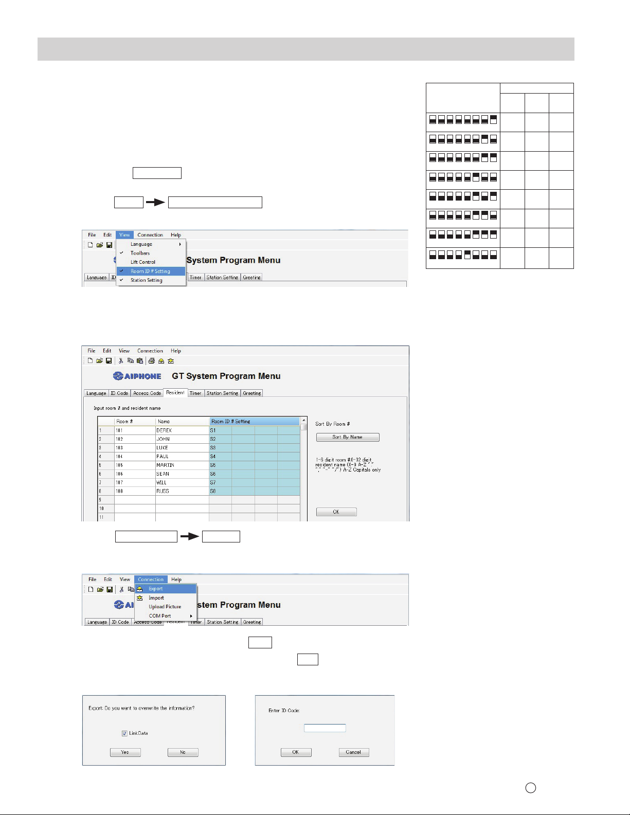
PROGRAMMING: ADDRESSING RESIDENCES VIA DIP SWITCH METHOD
Step 1: Set dip switches for all GT-1C7(-L), GT-1M3(-L) and GT-2C(-L) stations
using the chart example to the right.
(The full GT Dip Switch Setting Worksheet can be found on the CD included with the GT-BC.)
Step 2: Apply power to system.
Step 3: Install the GT software and USB cable driver on a computer running
Windows® XP, Windows Vista®, Windows® 7, or Windows® 8.
(Refer to page 6 for COM Port selection steps.)
Step 4: Open the GT software, select [GT System Mode].
Step 5: Select the
Resident
tab.
Step 6: Enter a Room # and Name for each residence to be programmed.
Step 7:
Select
View
Room ID # Setting
from the menu bar (see Figure 1).
Figure 1
Step 8: For each Binary Dip Switch setting made in Step 1, enter the appropriate
ID into the Room ID # Setting fi eld. Ensure that the correct correlation is
kept between residence name and actual unit (see Figure 2).
Figure 2
Binary
Dip Switch
48
152637
48
152637
48
152637
48
152637
48
152637
48
152637
48
152637
48
152637
Decimal
ID #
Exp
Std
(Sub 1)
S1 A1
A2
S2
A3
S3
S4
A4
A5
S5
A6
S6
A7
S7
S8
A8
Room ID # Setting:
Use S# for standard
system stations 1-48.
Use A# for expanded
system stations 1-250.
Use B# for expanded
system stations 251-500.
Exp
(Sub 2)
B251
B252
B253
B254
B255
B256
B257
B258
Step 9: Select
(Export sends data to the entrance station. Import pulls data from the entrance station.)
Connection
Export
from the menu bar (see Figure 3).
Figure 3
Yes
Step 10: Check the LinkData box and select
(see Figure 4).
Step 11: Enter ID code (initial setting is *1111) and click
Data will be transferred.
Figure 4 Figure 5
OK
(see Figure 5).
For residential/tenant stations
251-500, the dip switch
assignment is wthe same as
1-250.
Residential/tenant stations
1-250 wire to Sub 1A and
Sub 1B of the GT-BCX while
residences 251-500 wire to Sub
2A and Sub 2B
(see page 4).
Note: 8 binary digits allows
for 255 unique numbers. Only
numbers 1-250 are used by the
GT system.
Issue Date: Dec. 2016
8
FK2114 B 1216 SZ 59030
 Loading...