

Page 1
- 1 -
0207 AIC
GH SERIES
Apartment Intercom System
INSTALLATION &OPERATION MANUAL
Page 2
- 2 -
General Prohibitions
General Precautions
Prohibition to Dismantle the Unit
Prohibition on Subjecting the Unit to Water
WARNING
(Negligence could result in death or serious injury to people)
1. The unit must be installed and wired by a qualified technician.
2. Do not dismantle or alter the unit. Fire or electric shock could result.
3. Do not connect any non-specified power source to the +, - terminals, and do not
install two power supplies in parallel to a single input. Fire, damage to the unit,
or system malfunction could result.
4. Keep the unit away from water or any other liquid. Fire or electric shock could
result.
5. Do not plug or unplug with wet hands. Electric shock could result.
6. Do not put any metal or paper into the unit through the openings. Fire or
electric shock could result.
7. High voltage is present internally. Do not open the case. Electric shock could
result.
CAUTION
(Negligence could result in injury to people or damage to property)
1. Before turning on power, make sure wires are not crossed or shorted. Fire or
electric shock could result.
2. Do not manually hold down hook switch while testing and verifying chime or
call tone volume. The chime tone is very loud in earpiece,and could cause
hearing damage.
3. Do not install or make any wire terminations while power supply is plugged in.
It can cause electrical shock or damage to the unit.
4. Do not install the unit in a location subject to constant vibration or impact. If
dropped, injury or unit damage could result.
5. When mounting the unit on wall, install the unit in a convenient location, but
not where it could be jarred or bumped. Injury could result.
6. Do not alter or change wall-mounting of the unit. If dropped, it can cause injury.
7. Do not put high pressure on the video-monitor surface. If fractured, injury
could result.
8. If LCD is punctured, do not allow contact with the liquid crystal inside.
Inflammation could result. If necessary, gargle your mouth and clean your eyes
or skin with clear water for at least 15 minutes, and consult your doctor.
9. When cleaning outer surface with high-pressure water, be sure that the entrance
station will not be subjected to direct water pressure. Damage to the unit could
result.
10. To avoid system malfunction, do not install the unit in places;
1. high or extreme cold temperature,
2. subject to moisture or humidity extremes,
3. environmental conditions: dust, oil, chemicals, salt, etc.,
4. constant vibration or impact, and 5. steam or smoke.
11. Do not put anything on or cover the unit with cloth, etc. Fire or unit trouble
could result.
12. For DC powered systems, use Aiphone power supply model specified with
system. If non-specified product is used, fire or malfunction could result.
GENERAL PRECAUTIONS
1. All the units, except for entrance station, is designed for indoor use only. Do
not use outdoors.
2. The unit will be inoperative during a power outage.
3. In areas where broadcasting station antennas are close by, the intercom system
may be affected by radio frequency interference.
4. Keep the intercom wires more than 12 inches (30 cm) away from AC
100~240V wiring. AC induced noise and/or unit malfunction could result.
5. Keep the unit more than 1 m away from Radio or TV set.
6. When strong light comes in on the unit's screen, the image looks white or
silhouetted. But this is not a unit trouble.
PRECAUTIONS
Page 3

- 4 -
1
SYSTEM CONFIGURATION
GH-DA/A + GH-SW
GH-DA/A +
GH-NS, GH-10K
GH-VA + GH-DA/A +
GH-SW
GH-VA + GH-DA/A +
GH-NS, GH-10K
GH-BC
GH-VBC
2
B
A
C
1
3
E
D
F
5
K
J
L
4
H
G
I
6
N
M
O
8
U
T
V
7
R
Q
P
S
Y
X
W
Z
9
0
GH-MK
Max. 5
(3 per trunk)
Max. 2
GH-1KD
GH-1KD
GH-1KD
GH-VA
GH-DA/A
GH-4Z
GH-1KD
GH-1KD
GH-1KD
GH-1KD
a b
c d
e
1-1
GH-1KD + GH-HSGH-1MDGH-1AD
GH-VA
GH-1KD, GH-1MDGH-VBC GH-VBC GH-VBC
SW
SW
STD EXP
SW
STD EXP
SW
STD EXP
Max. 6
Max. 48
Max. 25 / Trunk
Max. 48
Max. 25 / Trunk
[1]
[2]
[3]
[4]
GH-VBC
b
a
e
c d
(1)
(2)
(3)
:A
:V
:P
()
[5]
[5]
[6]
[7]
[9]
[10]
[10]
[10]
[10]
[10]
[10]
[10]
[11] [12] [13]
[14]
DP
[8]
150 m 150 m
300 m
150 m
PS-2410LC
PS-2410LD
PS-2410DIN
AC AC
AC
[5]
PS24
PS24
PS24
PS24
PS24
PS24
[5]
[5]
GH-4Z
GH-1KD
GH-1KD
GH-1KD
GH-1KD
Max. 6
[9]
[10]
[10]
[10]
[10]
1
2
2
1
1
2
1
1
2
Trunk
#6 ~ #2
Trunk
#1
PS24PS24PS24
Page 4
- 5 -
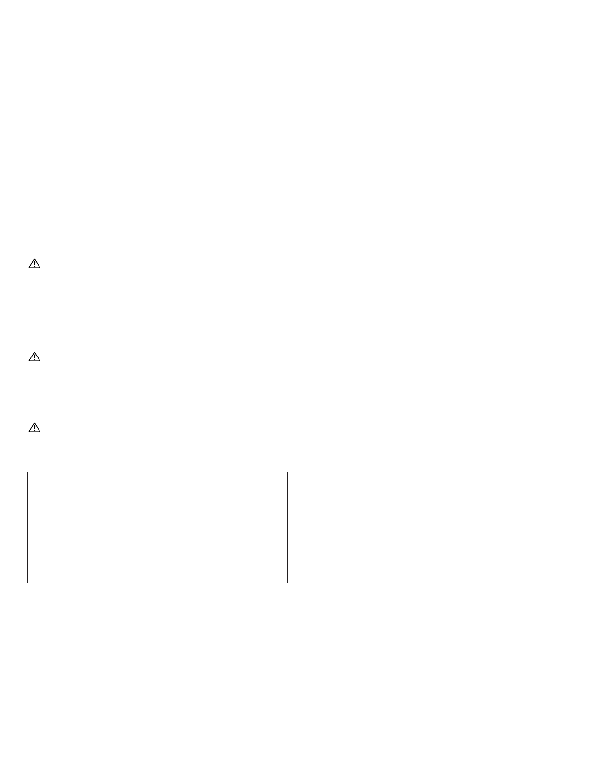
Standard System Configuration
(1) Audio signal line
(2) Video signal line
(3) Power supply line
a. Entrance station (For details, see 2-1 and 2-2)
[1] Audio/video + digital name scrolling type
GH-VA + GH-DA/A + GH-NS, GH-10K
[2] Audio/video + direct selection type
GH-VA + GH-DA/A + GH-SW
[3] Audio + digital name scrolling type
GH-DA/A + GH-NS, GH-10K
[4] Audio + direct selection type
GH-DA/A + GH-SW
b. Bus control units
[5] Power supply PS-2410LC, PS-2410LD, PS-2410DIN
[6] Video Bus control unit GH-VBC
∗ GH-VBC can be used as an extension adaptor as well. To do so,
set the setting switch to "EXP." (2 units per trunk line)
Even if two GH-VBC units are used as extension adaptors
(SW: EXP), the wiring distance from the video Bus control
unit (SW: STD) to the farthest video residential station is
limited to 300 m (980').
[7] Bus control unit GH-BC
[8] Distribution terminal (junction): sold separately
c. Residential station (For details, see 2-4):
Station-to-station wiring
d. Residential station (For details, see 2-4): Homerun wiring
Do not mix station-to-station wiring and homerun wiring on a
single trunk line.
[9] 4-way video junction unit GH-4Z
[10] Color video residential station GH-1KD
[11] Audio residential station GH-1AD
[12] Black &White video residential station GH-1MD
Station-to-station wiring is not possible for GH-1MD
[13]
Color video residential station + handset (option) GH-1KD + GH-HS
e. Security Guard Station
[14] Security guard station GH-MK
1-1
Capacity
Entrance Station Maximum 5 stations
(up to 3 stations per trunk)
Residential Station Maximum 48 stations
(up to 25 stations per trunk)
Security Guard Station Maximum 2 stations
Residential stations
in the same residence
Maximum 4 stations
(up to 2 monitor stations)
4-way video junction unit Maximum 6 units per trunk
Bus control unit Maximum 1 unit per system
Page 5

- 3 -
1 SYSTEM CONFIGURATION
Standard System Configuration 4
Expanded System Configuration 6
Wiring Distance 7
2 COMPONENTS
Unit (Entrance Station) 8
Combination Examples for Entrance Station, Unit (Bus Control Unit and Others) 9
Residential Station, Security Guard Station 10
3 MOUNTING
Mounting the Entrance Station (1) 11
Mounting the Entrance Station (2), (3) 12
Bus Control Unit and Power Supply 13
Residential Station, Optional Handset 14
Security Guard Station (Desk-top Mounting Using the GFW-S Stand), (Mounted on Wall) 15
4 WIRING
Standard System 16
Standard System (1) 18
Standard System (2) Station-to-Station Wiring 19
Standard System (3) Homerun Wiring 20
Expanded System 22
External Signaling Relay Connection 25
5 NAMES (ENTRANCE STATION)
Entrance Station (GH-VA, GH-DA/A, GH-NS, GH-10K), (GH-DA/A, GH-SW) 26
6 NAMES (RESIDENTIAL STATION)
Residential Station (GH-1AD, GH-1KD) 26
Residential Station (GH-1MD) 27
7 NAMES (SECURITY GUARD STATION)
Security Guard Station (GH-MK) 27
8 SETTING UP (ENTRANCE STATION)
Adjusting the Camera Angle, Entering Names and Addresses 28
Making Adjustments with the Mounting Gauge 29
Setting up the System 30
Programming (GH-NS) 31
Program Mode (GH-NS) 32
9 SETTING UP (SECURITY GUARD STATION)
Programming (GH-MK) 34
Program Mode (GH-MK) 35
10 OPERATIONS (ENTRANCE STATION)
Calling a Residential Station 38
Calling the Security Guard Station, Door Release 39
11 OPERATIONS (RESIDENTIAL STATION)
Replying to a Call 39
Calling from the Doorbell (at Individual Door), Door Release, Turning on the Entrance Light,
Calling the Security Guard Station, Automatic Entry (Doctor Call) Option 40
Emergency Alarm, Monitoring Entrance Stations 41
12 OPERATIONS (SECURITY GUARD STATION)
Replying to a Call from an Entrance Station, Replying to a Call from a Residential Station 42
Calling an Entrance Station, Calling a Residential Station 43
Calling Another Security Guard Station, Emergency Call 44
Reception mode, Calling from the Doorbell, Missed call 45
13 TECHNICAL PRECAUTIONS 46
14 SPECIFICATIONS 46
Page 6
- 6 -
GH-VA + GH-DA/A +
GH-NS, GH-10K
GH-MK
Max. 8
(3 per trunk)
Max. 2
GH-VA
GH-VA
GH-1KD / GH-4Z
a
e
1-2
#2
#3
#4
#2
#3
#4
(1)
(2)
(3)
:A
:V
:P
[1]
1
#1
#2
a
e
a
e
f
GH-BC
GH-BC
2
B
A
C
1
3
E
D
F
5
K
J
L
4
H
G
I
6
N
M
O
8
U
T
V
7
R
Q
P
S
Y
X
W
Z
9
0
GH-DA/A
GH-DA/A
GH-BC
GH-VBC
b
GH-VBX
GH-BCX/A
[2]
#1
#1
f
#2
#4
#3
DP
GH-VA + GH-DA/A +
GH-NS, GH-10K
GH-MK
Max. 8
(3 per trunk)
Max. 2
a
e
2
B
A
C
1
3
E
D
F
5
K
J
L
4
H
G
I
6
N
M
O
8
U
T
V
7
R
Q
P
S
Y
X
W
Z
9
0
#2
[3]
DP
[3]
DP
[3]
PS-2410LC
PS-2410LD
PS-2410DIN
AC AC
AC
Max. 125
Max. 25 / Trunk
c d
()
[4]
[4]
[4]
[4]
[4]
[4]
[4]
[4]
[4]
2
#1
#2
#3
#4
b c d
()
b
c d
()
b
c d
()
b c d
()
PS24
PS24
PS24
PS24
PS24
PS24
PS24
PS24
PS24
PS24
Page 7
- 7 -
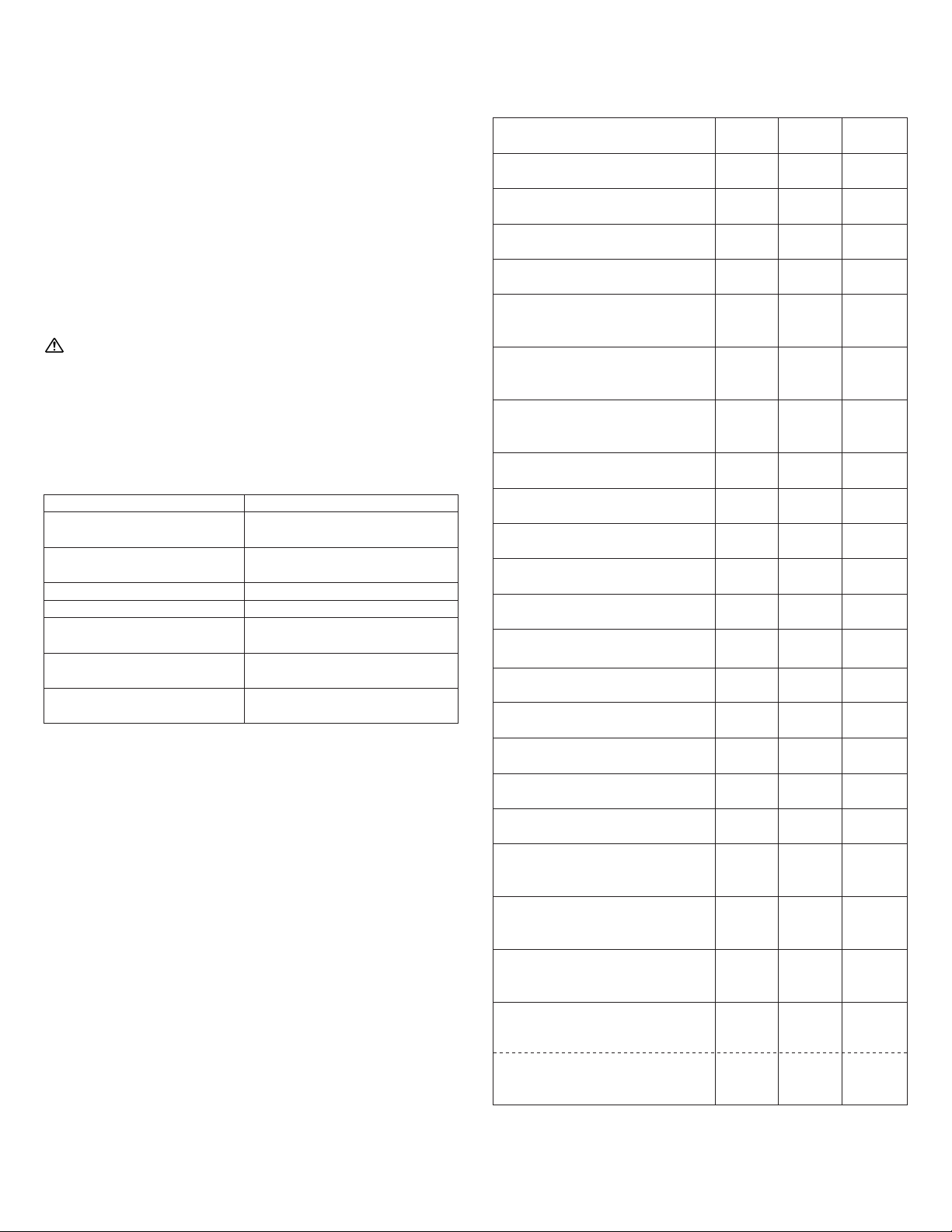
1-2
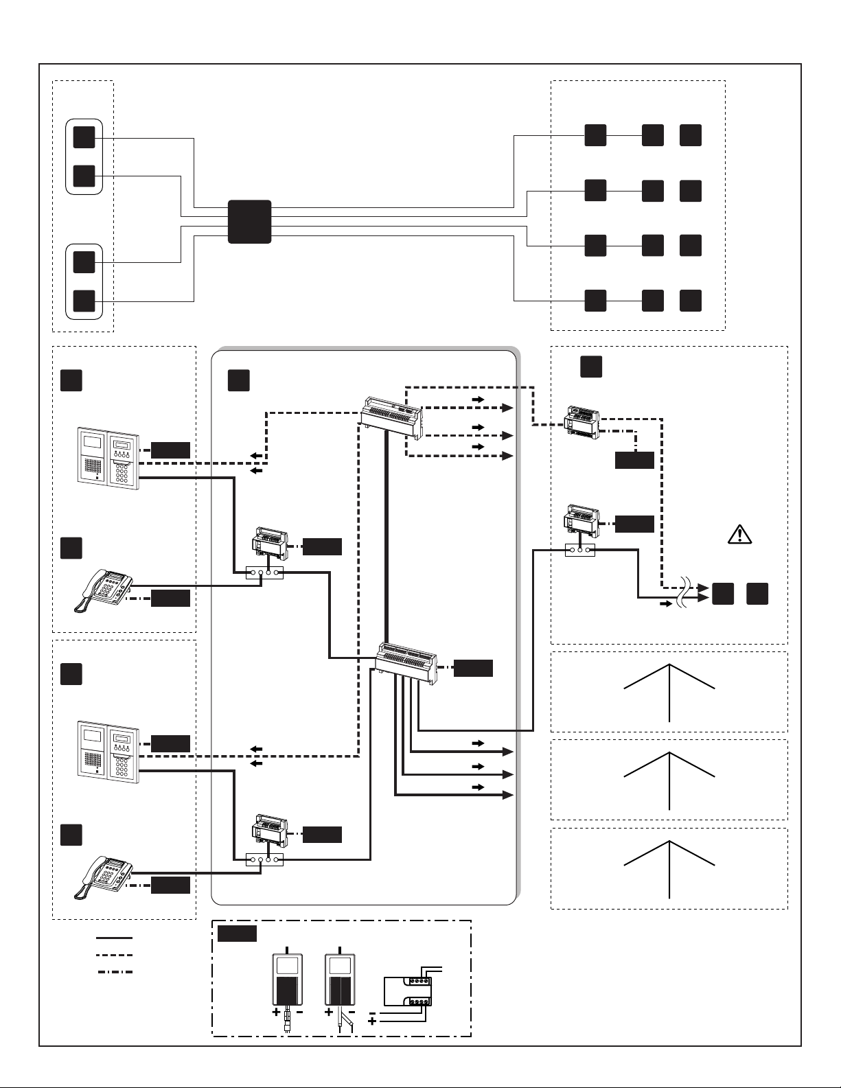
Expanded System Configuration Diagram
1. Common trunk line #1, 2
2. Sub trunk line #1 - 4
Sub trunk line #2 - #4 are the same as #1. Maximum 125 units
per sub trunk line.
(1) Audio signal line
(2) Video signal line
(3) Power supply line
a. Entrance station (For details, see 2-1 and 2-2)
b. Bus control unit
c. Residential station (For details, see 2-4):
Station-to-station wiring (For details, see 1-1)
d. Residential station (For details, see 2-4):
Homerun wiring (For details, see 1-1)
Do not mix station-to-station wiring and homerun wiring on a
single trunk line.
e. Security Guard Station
f. Expanded Bus control unit
[1] Expanded video Bus control unit GH-VBX
[2] Expanded Bus control unit GH-BCX/A
[3] Distribution terminal (junction): Not included
[4] Power supply PS-2410LC, PS-2410LD, PS-2410DIN
1-3
Wiring Distance
∗ DP = Distribution Point
Capacity
Entrance Station Maximum 16 stations
(up to 3 stations per trunk)
Residential stations
per Sub trunk line
Maximum 125 stations
(up to 25 stations per trunk)
Residential Station Maximum 500 stations
Security Guard Station Maximum 4 stations
Residential stations
in the same residence
Maximum 4 stations
(up to 2 monitor stations)
Bus control unit
per Common trunk line
Maximum 1 unit
Bus control unit
per Sub trunk line
Maximum 1 unit
Diameter of wires
0.65 mm
(22 AWG)
0.8 mm
(20 AWG)
1.0 mm
(18 AWG)
GH-BC - DP
DP - GH-DA/A
GH-VBC - GH-VA
GH-MK - DP
DP - farthest residential station
(R1-R2)
(Includes system with GH-4Z)
GH-VBC - farthest residential station
(1 monitor unit/residence)
(Includes system with GH-4Z)
GH-VBC - farthest residential station
(2 monitor units/residence)
(Includes system with GH-4Z)
GH-VBC (SW: STD)
- GH-VBC (SW: EXP)
GH-BC - power supply
GH-VBC - power supply
GH-NS - power supply
GH-MK - power supply
5 m
(16')
5 m
(16')
5 m
(16')
300 m
(980')
300 m
(980')
300 m
(980')
300 m
(980')
300 m
(980')
300 m
(980')
5 m
(16')
5 m
(16')
300 m
(980')
300 m
(980')
150 m
(500')
150 m
(500')
100 m
(330')
-
-
GH-BCX/A - power supply 5 m
(16')
5 m
(16')
-
-
-
150 m
(490')
-
-
-
-
100 m
(330')
100 m
(330')
50 m
(165')
-
-
-
-
-
2500 m
(8200')
--
300 m
(980')
--
150 m
(500')
--
300 m
(980')
--
300 m
(980')
--
300 m
(980')
150 m
(500')
-
-
-
150 m
(500')
100 m
(330')
-
150 m
(500')
100 m
(330')
50 m
(165')
150 m
(500')
Standard system
total wiring distance
each
2500 m
(8200')
--
each
2500 m
(8200')
--
Expanded system
total per Common trunk line
(maximum 2 trunk lines)
Expanded system
total per Sub trunk line
(maximum 4 trunk lines)
GH-BC - GH-BCX/A
GH-VBC - GH-VBX
GH-DA/A - GH-BCX/A
GH-VA - GH-VBX
GH-BCX/A - farthest residential station
(R1-R2)
(Includes system with GH-4Z)
GH-VBX - farthest residential station
(1 monitor unit/residence)
(Includes system with GH-4Z)
GH-VBX - farthest residential station
(2 monitor units/residence)
(Includes system with GH-4Z)
Page 8
- 8 -
2
COMPONENTS
2-1
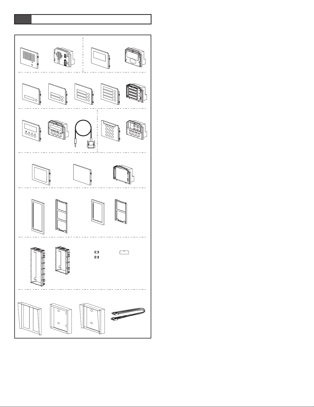
Unit (Entrance Station)
[1] Speech module panel GH-DP
[2] Speech module GH-DA/A
[3] Camera module panel GF-VP
[4] Camera module GH-VA
[5] 1-call button panel GF-1P
[6] 2-call button panel GF-2P
[7] 3-call button panel GF-3P
[8] 4-call button panel GF-4P
[9] Call switch module GH-SW
[10] Digital name scroll module panel GF-NSP
[11] Digital name scroll module GH-NS
[12] RS-232C cable (included with GH-NS)
[13] Digital keypad module panel GF-10KP
[14] Digital keypad module GH-10K
[15] Address module panel GF-AP
[16] Blank panel GF-BP
[17] Address module GH-AD
[18] 3-module front frame GF-3F
[19] 2-module front frame GF-2F
[20] Mounting bracket (included with GF-3F and GF-2F)
[21] 3-module back box GF-3B
[22] 2-module back box GF-2B
[23] Joint pipe (included with GF-3B and GF-2B)
[24] Mounting gauge (included with GF-3B and GF-2B)
[25] Rain hood GF-nH (option)
[26] Surface-mount box GF-202B (option; for Europe Only)
[27] Hooded surface-mount box GF-nHB (option)
[28] 80 cm (32") connection cable GF-C (option)
[1] [2] [3] [4]
[5] [6] [7] [8] [9]
[10] [11] [12] [13]
[15] [16] [17]
[18] [20] [19] [20]
[21] [22] [23] [24]
[25] [26] [27] [28]
[14]
Page 9
- 9 -
2-2
2-3
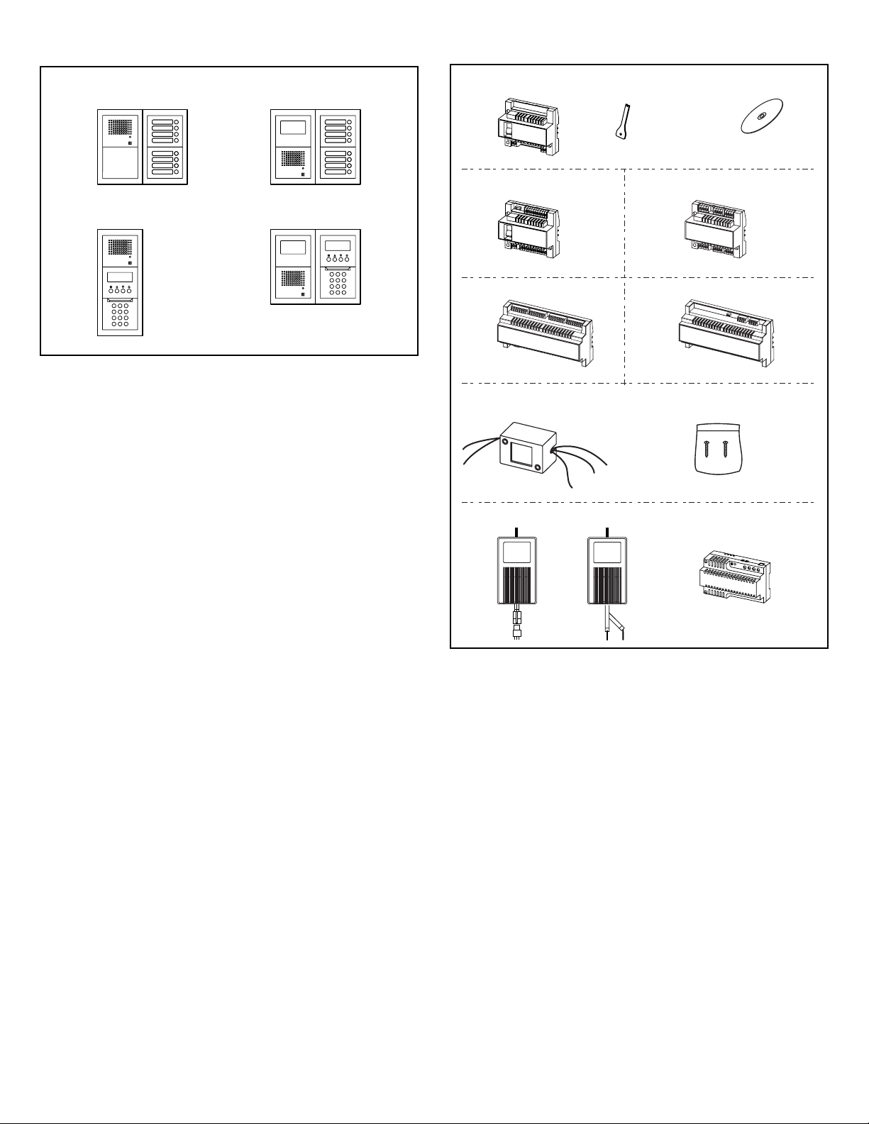
Combination Examples for Entrance Station
1. Audio only. Direct selection (8 stations).
2. Audio/video. Direct selection (8 stations).
3. Audio only. Digital name scrolling.
4. Audio/video. Digital name scrolling.
Unit (Bus Control Unit and Others)
[1] Bus control unit GH-BC (mounting bracket is not included)
[2] Special screwdriver (included with GH-BC)
[3] CD (contains operation manual and setup tool)
(included with GH-BC)
[4]
Video Bus control unit GH-VBC (mounting bracket is not included)
[5]
4-way video junction unit GH-4Z (mounting bracket is not included)
[6] Expanded Bus control unit GH-BCX/A (mounting bracket is
included)
[7]
Expanded video Bus control unit GH-VBX (mounting bracket is
included)
[8] External signaling relay GH-RY
[9] Mounting screws (included with GH-RY)
[10] Power supply PS-2410LC
[11] Power supply PS-2410LD
[12] Power supply PS-2410DIN
AIPHONE
AIPHONE
AIPHONE
AIPHONE
12
34
[1] [2] [3]
[4]
[6]
[5]
[8]
[10] [11] [12]
[7]
[9]
Page 10
- 10 -
2-5
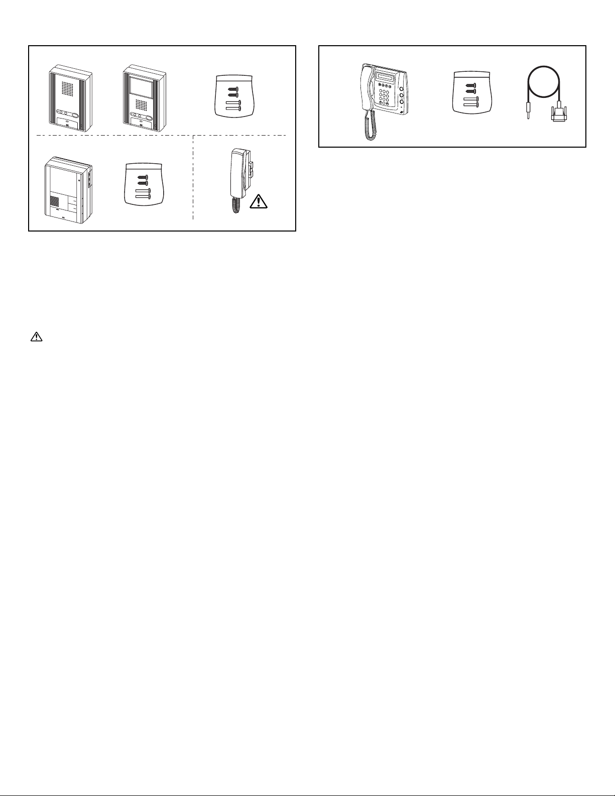
Security Guard Station
[1] Security guard station GH-MK
[2] Mounting screws (enclosed with GH-MK)
[3] RS-232C cable (enclosed with GH-MK)
2-4
Residential Station
[1] Audio residential station GH-1AD
[2] Color monitor residential station GH-1KD
[3] Mounting screws (enclosed with GH-1AD and GH-1KD)
[4] Black-and-white monitor residential station GH-1MD
[5] Mounting screws (enclosed with GH-1MD)
[6] Optional handset GH-HS (mounting screws are attached back
side)
GH-HS can be installed only for the color monitor residential
station GH-1KD.
[1] [2]
2
B
A
C
1
3
E
D
F
5
K
J
L
4
H
G
I
6
N
M
O
8
U
T
V
7
R
Q
P
S
Y
X
W
Z
9
0
[3]
[1] [2] [3]
[4] [5] [6]
Page 11
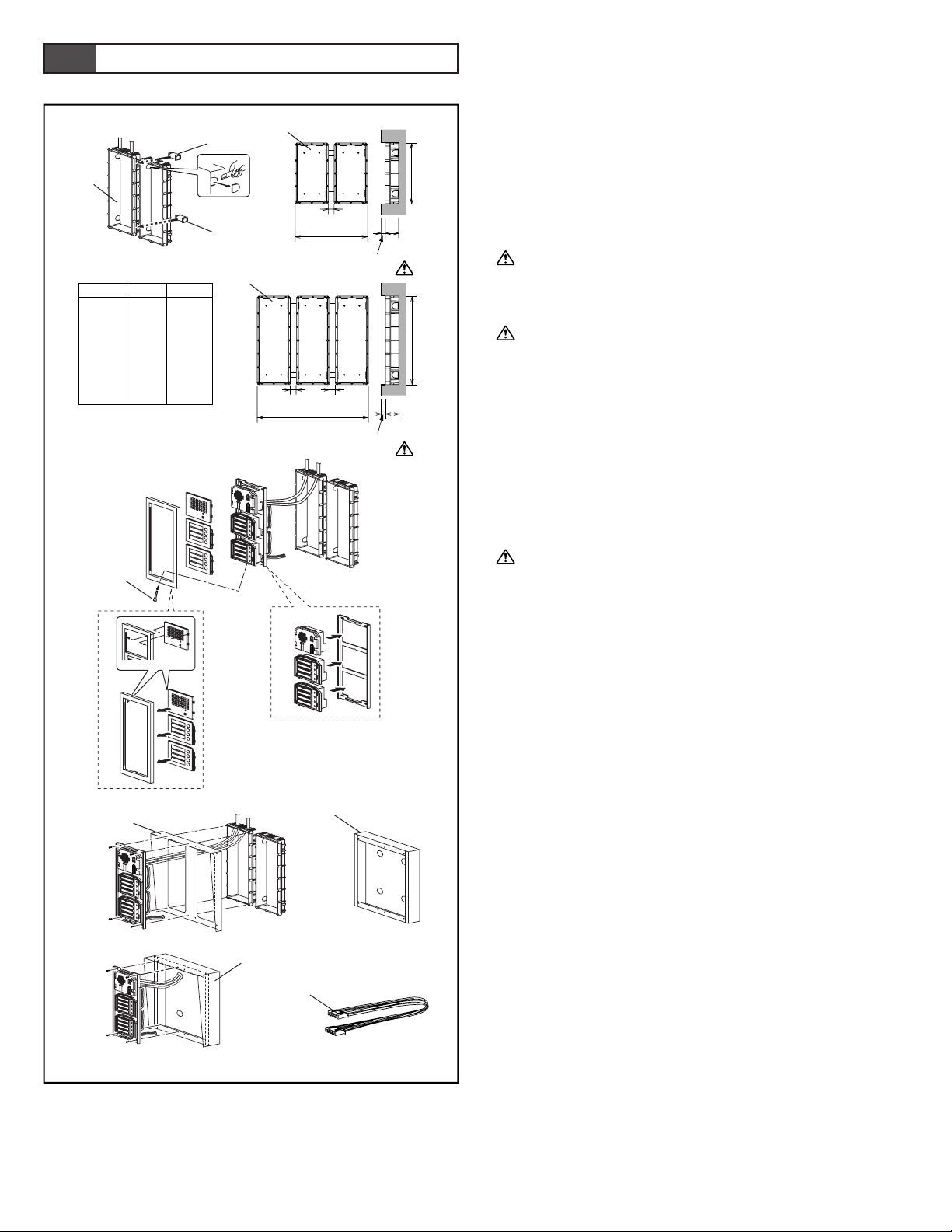
- 11 -
Mounting the Entrance Station (1)
[1] Back box
[2] Joint pipe
[3] Back box assembly dimensions
[4] Special screwdriver (enclosed with GH-BC)
1. Mounting the back box
• Make a hole for the cable.
• Use the joint pipe to assemble the back box.
• Make sure the back box is mounted level.
• Mount the camera and GH-NS module at eye-level for the
average height of an adult.
Do not mount the back box on a surface that is recessed by 15
mm (1/2") or more from the external surface of the wall.
2. Set up the modules.
• For information on what modules can be used, see 2-1 and 2-2.
Up to 6 GH-SW modules can be used. If you would like to
connect 7 modules or more, please contact Aiphone.
3. Mount each module panel to the front frame.
• Mount the panels from behind the front frame.
•
Insert the notch into the slots on both sides and slide it downward.
4. Mount each module to the mounting bracket.
•
Set the modules in the mounting bracket until they click in place.
5. Options
a. Rain hood GF-H
b. Surface-mount box GF-202B
c. Hooded surface-mount box GF-HB
d. 80 cm (32") connection cable GF-C
Peel off protection film on GH-NS display.
3-1
3
MOUNTING
1
2
3
4
5
a
b
295mm
(11-5/8")
W
44mm
(1-3/4")
25mm
(1")
25mm
(1")
25mm
(1")
W
200mm
(7-7/8")
44mm
(1-3/4")
15mm
(9/16")
x 1
x 2
x 3
x 4
x 5
x 6
x 7
x 8
x 9
110
245
380
515
650
785
920
1055
1190
W (mm)
4-5/16"
9-5/8"
15"
20-1/4"
25-9/16"
30-7/8"
36-1/4"
41-9/16"
46-7/8"
W (inch)GF-2B/3B
15mm
(9/16")
[4]
[2]
[3]
[1]
[2]
c
d
[1]
[1]
Page 12
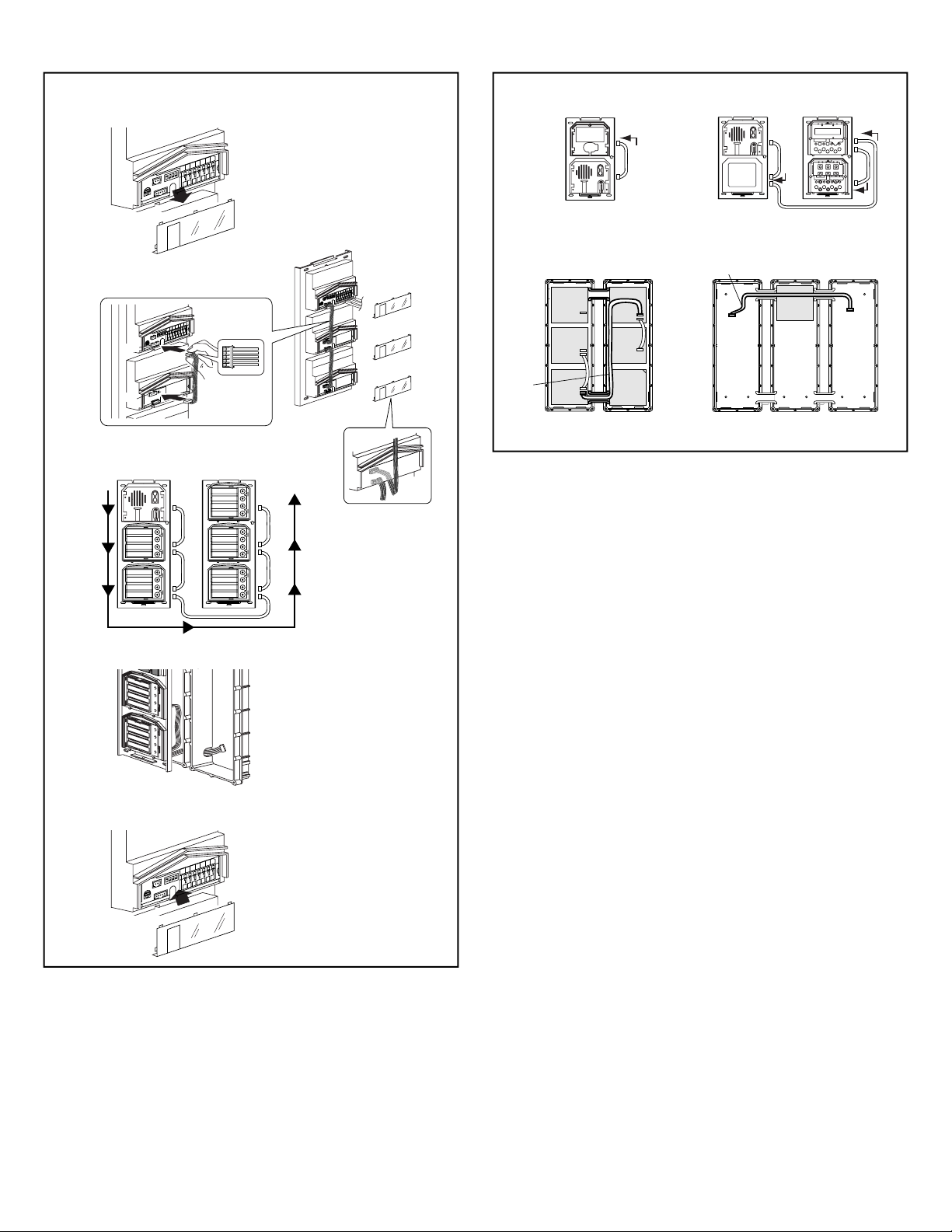
- 12 -
3-2 3-3
Mounting the Entrance Station (3)
1. Example of interconnection of modules.
2. Use GF-C to connect to the name scrolling module.
3. To position the speech module in the center row, run GF-C
through the joint pipe in advance.
Mounting the Entrance Station (2)
1. Remove the terminal cover.
2. From the speech module to the next module, insert the attached
connector into the socket. Make sure to run the cable under the
terminal cover for protection.
3. Connect the connectors between the modules with cables.
4. Run the connection cable through the joint pipe (which you
should have made open in advance) and connect CN1 of GHSW to the next row.
5. Put back the terminal cover.
1
23
CN3
CN1
GH-VA
GH-DA/A
CN1
CN3
CN100
CN2
CN1
CN2
GH-DA/A
GH-AD
GH-NS
GH-10K
GF-C
GH-DA/A
GH-AD
GF-BP
GF-3B GF-3B
GH-10K
GH-VA GH-NS
GF-C
GH-DA/A
GF-3B GF-3B GF-3B
1
2
3
4
5
1
0
3
O
N
1
2
3
4
C
N
2
C
N
1
GH-DA/A
1
0
3
ON
1
2
3
4
C
N
2
C
N
1
GH-DA/A
1
0
3
O
N
1
2
3
4
O
N
O
N
1
2
1
0
3
O
N
1
2
3
4
O
N
CN1
GH-DA/A
CN2
GH-SW
CN2
CN1
CN2
CN1
CN2
CN1
CN2
CN1
CN2
CN1
Page 13
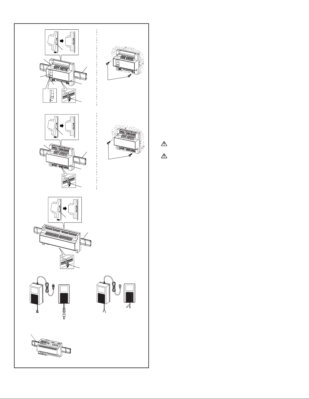
- 13 -
3-4
Bus Control Unit and Power Supply
[1] Din rail (W-DIN11)
[2] Screw hole
[3] POWER switch
[4] Power On LED (green)
[5] Lock release lever
[6] Wall mounting screws (x2)
1. Mount GH-BC and GH-VBC to the Din rail. Click unit into
place.
∗ To remove GH-BC and GH-VBC, pull the lock release lever
down.
∗ If there is a problem with the system, check the power supply
wiring. Turn off the GH-BC and GH-VBC power switch and
then turn the switch back on after four seconds. This will reset
the entire system.
2. Mount GH-BC and GH-VBC directly to the wall surface.
3. Mount GH-4Z to the Din rail.
∗ To remove GH-4Z, pull the lock release lever down.
4. Mount GH-4Z directly to the wall surface.
5. Mount GH-BCX/A and GH-VBX to the Din rail. To remove
GH-BCX/A and GH-VBX, pull the lock release lever down.
1. GH-BCX/A and GH-VBX cannot be mounted directly to
the wall surface.
2. The length of the connecting cable between the GH-BCX/A
and GH-VBX is 40 cm (15-3/4"). Therefore, mount the GHBCX/A and GH-VBX adjacent to each other.
6. Power supply PS-2410LC, PS-2410LD, PS-2410DIN
Red: +
Black: -
GH-BC
GH-VBC
GH-4Z
GH-BC
GH-VBC
GH-4Z
GH-BCX/A
GH-VBX
ON
OFF
[1]
[6]
[1]
[1]
[1]
[2]
[5]
[4]
[2]
[3]
[5]
[5]
[1]
[1]
[2]
[2]
[6]
12
3
5
6
4
+
–
+
–
+–
PS-2410LDPS-2410LC
PS-2410DIN
[1]
Page 14
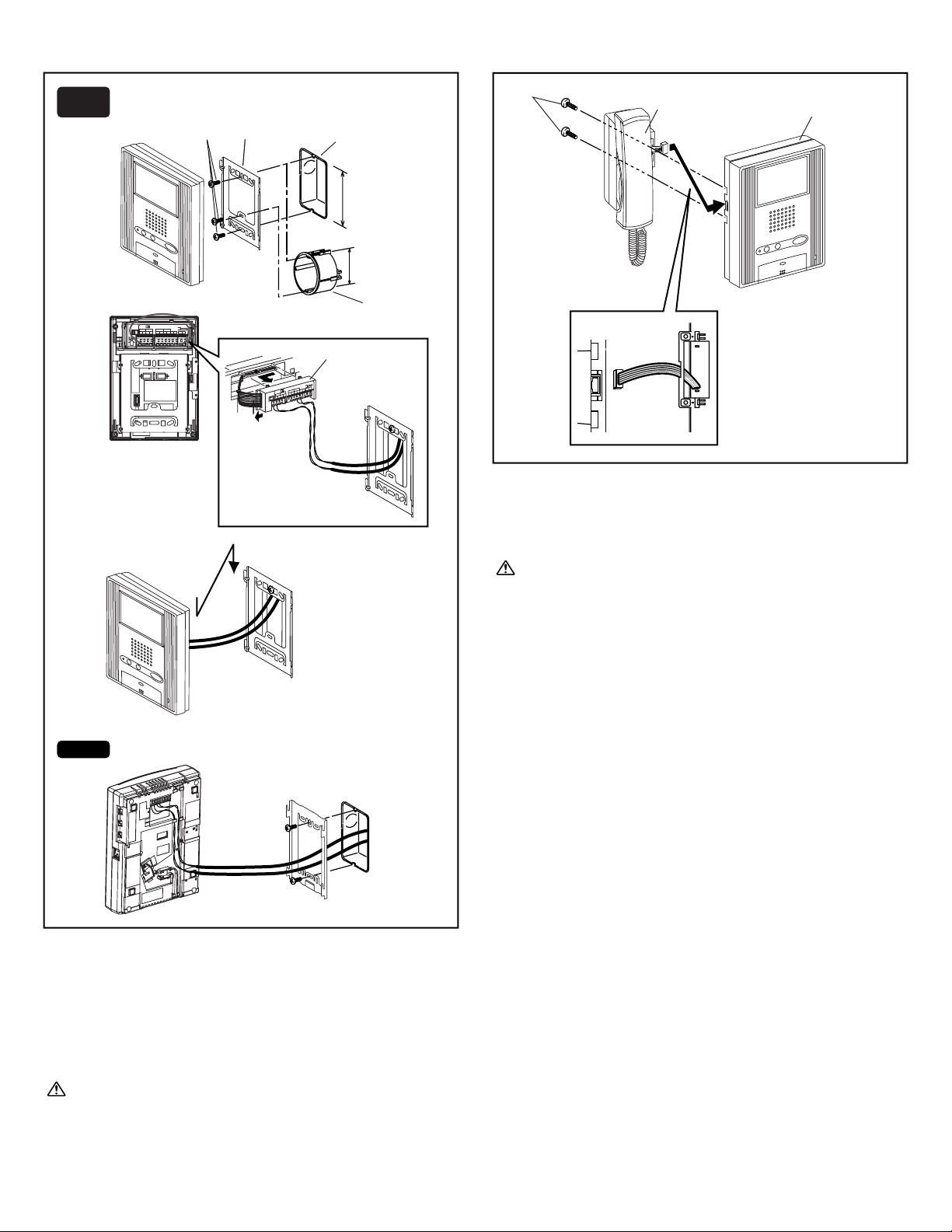
- 14 -
3-5
3-6
Residential Station
[1] Mounting screws (x2)
[2] Mounting bracket
[3] 1-gang box or round back box
[4] Terminal block (GH-1AD, GH-1KD)
1. Mount the mounting bracket on the 1-gang box.
2. Connect the wiring to the terminal block.
3. Mount the station unit to the mounting bracket.
Strip away the jacket of the cable and insert all wires into the
slots in an orderly fashion. Failure to do so could result in
pinching that may damage the wiring.
NOTE: To remove the terminal block, slide the terminal block
and pull it out. (GH-1AD, GH-1KD)
Optional Handset
[1] Chassis
[2] Handset (GH-HS)
[3] Screws (x2)
• Connect the station unit joint connector.
GH-HS can be installed only for the color monitor residential
station (GH-1KD).
SW1 A B
IN OUT
R1 R2 R1 R2 C
0.65 10 9
CE K KE
Do not remove the wires (For end users)
[3]
[3]
[2]
[1]
[4]
[1]
[2]
[3]
OR
60mm (2-3/8")
83.5mm (3-5/16")
1
2
3
SW
1
AB
IN
O
U
T
R
1R
2
R
1R
2
C
0
.
6
5
1
0
9
C
EK
K
E
D
o n
ot rem
ove the
w
ires (For end u
sers)
GH-1MD
GH-1AD
GH-1KD
Page 15
- 15 -
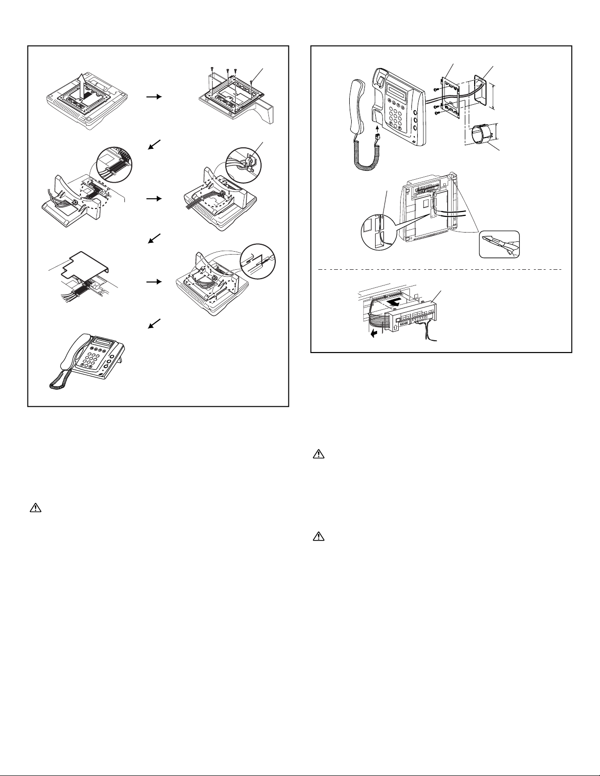
Security Guard Station (Desk-top Mounting Using GFW-S Stand)
[1] Screws included with GFW-S (x4)
[2] Cable tie included with GFW-S
1. Separate the mounting bracket and the protective cover from
the back of the unit.
2.
Mount the mounting bracket to GFW-S as shown in the drawing.
3. Connect the wiring to the terminal block, inserting the wires
into the slots in an orderly fashion.
Set the wiring in place with the cable tie to ensure that they
are not pulled out.
4. Cover the terminal section with the protective cover.
5.
Insert the mounting bracket latch and slide it upward until it locks.
Security Guard Station (Wall-mounting)
[1] 1-gang box or round back box
[2] Mounting bracket
[3] Wiring slot
[4] Terminal block
1. Mount the mounting bracket on the 1-gang box.
2. Connect the wiring to the terminal block.
3. Mount the station unit to the mounting bracket.
Strip away the jacket of the cable and insert all wires into the
slots in an orderly fashion. Failure to do so could result in
pinching that may damage the wiring.
NOTES: 1. To remove the terminal block, slide it to the left and
pull it out.
2. To wire along the main unit surface, use a nipper to
cut the section shown on the drawing.
Peel off protection film on display.
3-7 3-8
12
3
45
2
B
A
C
1
3
E
D
F
5
K
J
L
4
H
G
I
6
N
M
O
8
U
T
V
7
R
Q
P
S
Y
X
W
Z
9
0
OR
60mm (2-3/8")
83.5mm (3-5/16")
2
B
A
C
1
3
E
D
F
5
K
J
L
4
H
G
I
6
N
M
O
8
U
T
V
7
R
Q
P
S
Y
X
W
Z
9
0
[1]
[2]
[1]
[2]
[3]
[1]
[4]
Page 16
- 16 -
4
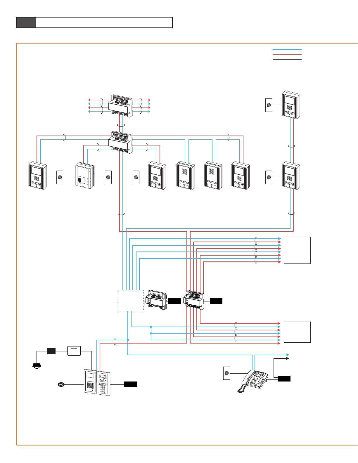
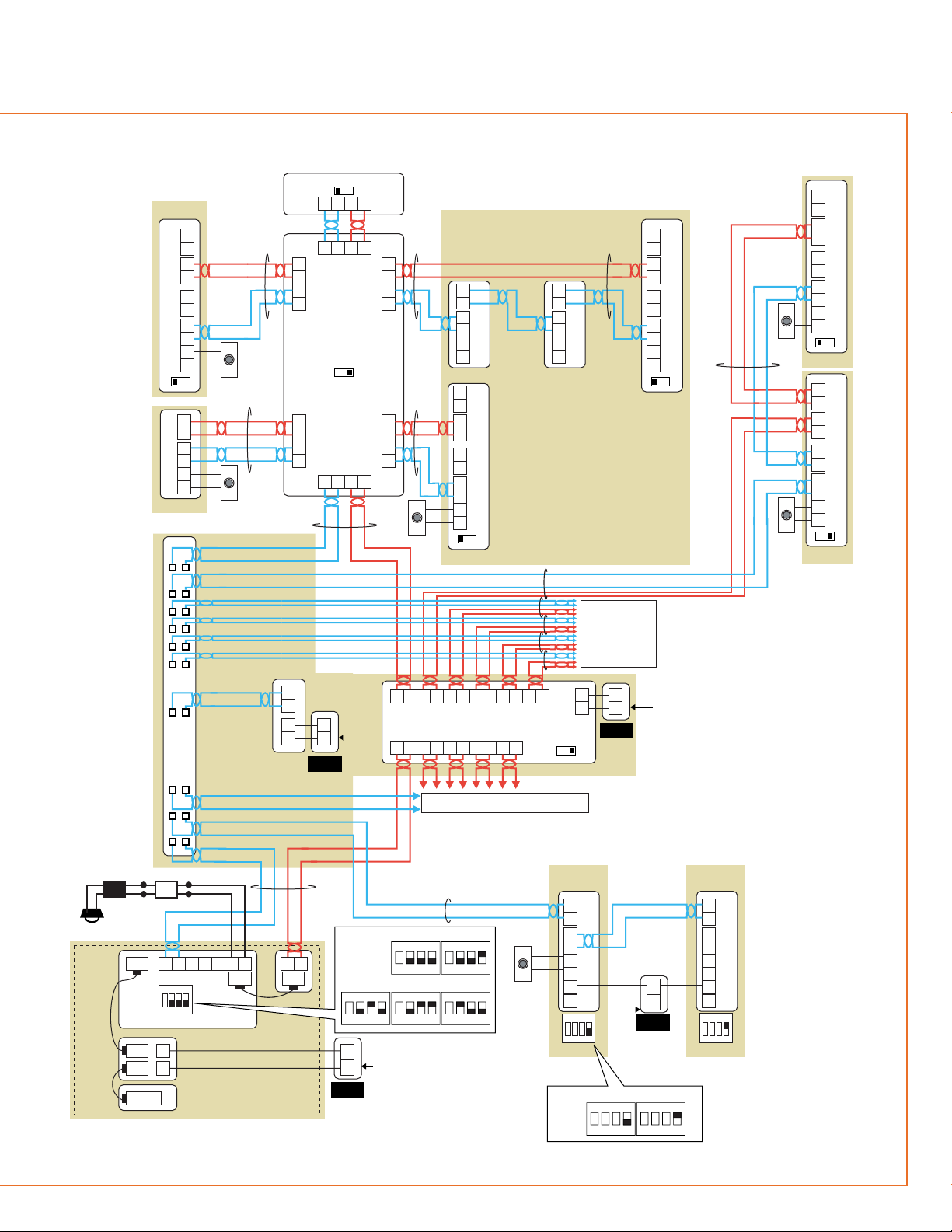
WIRING
1P
Entrance
#2 - #5
Trunk line
#3 - #6
Door release
Entrance station
#1
1P(Audio)
1P(Video)
1P
GH-BC
GH-MK #1
GH-VBC
1Px2
Trunk line #1
Trunk line #2
1Px2
1P 1P
1Px2
1Px2
1Px2
1Px2
1Px2
PS24 PS24
PS24
Distribution
point
R1 R2
GH-4Z
GH-4Z
1Px2
1Px2
1Px2 1Px2
1Px2
1P 1P
1Px2
1Px2
1Px2
1Px2
Doorbell
GH-1MD
GH-1KD GH-1AD GH-1AD GH-1KDGH-1KD
GH-1KD
GH-MK
#2
GH-1KD
Homerun wiring with GH-4Z Station-to-station wiring
Light control
Timer
Light
AC
GH-RY
Standard system
Doorbell
On the same trunk line, do not have two wiring methods mixed,
Station-to-station wiring and homerun wiring with GH-4Z
GH-1MD, unlike GH-1KD,
is only available to connect
on a trunk line
with GH-4Z used
Max. 4 apartment stations can be linked per Residence
(including max. 2 monitor stations)
Capacity
5 Entrance stations
2 Security guard stations
48 Residential stations
PS24
DoorbellDoorbellDoorbell
Doorbell
2
B
A
C
1
3
E
D
F
5
K
J
L
4
H
G
I
6
N
M
O
8
U
T
V
7
R
Q
P
S
Y
X
W
Z
9
0
Page 17
- 17 -
Light
Orange
Orange
White
Blue
GH-4Z
B1
B2
R1
R2
B1 B2R1 R2
B1 B2R1 R2
B1 B2R1 R2
B1
B2
R1
R2
OUT 3 OUT 4
B1
B2
R1
R2
B1
B2
R1
R2
OUT 1
LINE OUT
LINE IN
OUT 2
BA
GH-4Z
BA
BA
1Px2 1Px2
1Px2 1Px2
1Px2
Terminate
the last GH-4Z
1Px2
1Px2
1Px2
1P
R1
R2
B1
B2
C
CE
C
CE
B1
B2
B1
B2
OUT
IN
R1
R2
R1
R2
OUT
IN
GH-1MD
GH-1KD
GH-1KD
OUT
OUT
IN
IN
OUT
IN
C
CE
B1
B2
B1
B2
R1
R2
R1
R2
BA
GH-1KD
GH-1ADGH-1AD
OUT
IN
OUT
IN
C
CE
B1
B2
B1
B2
R1
R2
R1
R2
BA
GH-1KD
OUT
IN
OUT
IN
C
CE
B1
B2
B1
B2
R1
R2
R1
R2
BA
R1
R2
R1
R2
C
CE
OUT
IN
R1
R2
R1
R2
C
CE
Trunk line
#3 - #6
1Px2
1Px2
B1 B2B1 B2
A1 A2
B1 B2B1 B2 B1 B2B1 B2
OUT1
IN1
A1 A2
IN2
A1 A2
IN3
A1 A2
IN4
A1 A2
IN5
OUT2 OUT3 OUT4 OUT5 OUT6
+
R1
R2
+
-
AC
GH-BC
GH-VBC
+
-
AC
+
-
AC
+
Video Entrance station #2 - #5
GH-1KD
OUT
IN
OUT
IN
C
CE
B1
B2
B1
B2
R1
R2
R1
R2
BA
R1 R2
ELB ELC ELM+RY RY
-
CN2
CN1
GH-DA/A
GH-RY
GH-NS
GH-10K
GH-VA
GH-MK
#2
GH-MK
#1
+
-
CN3
CN100
C
CE
+
-
R1
R2
R1
R2
C
CE
R1
R2
R1
R2
Distribution
point
SW1
SW1
ONON
1234
SW2
1ON234
1234
IN
IN
--
STDEXP
Light control
Timer
Entrance station #1
Door
bell
+
-
AC
Doorbell
Doorbell
Doorbell
Doorbell
Door
bell
PS24
PS24
PS24
PS24
Homerun wiring with GH-4Z
Trunk line #1
Station-to-station wiring
Trunk line #2
CN1
CN3
A1 A2
#1 #2
SW1
ON
1 2 3
4
ON
1 2 3
4
#1 #2
#3 #4 #5
SW2
ON
1
2 3
4
ON
1
2 3
4
ON
1
2 3
4
ON
1
2 3
4
ON
1
2 3
4
Page 18
- 18 -
IN1 IN2 IN3 IN4 IN5
OUT1 OUT2 OUT3 OUT4 OUT5 OUT6
A1 A2A1 A2A1 A2A1 A2A1 A2
B1 B2B1 B2B1 B2B1 B2B1 B2B1 B2
+ –
GH-VBC
IN1 IN2 IN3 IN4 IN5
OUT1 OUT2 OUT3 OUT4 OUT5 OUT6
A1 A2A1 A2A1 A2A1 A2A1 A2
B1 B2B1 B2B1 B2B1 B2B1 B2B1 B2
+ –
GH-VBC
GH-VA
#2 - #5
GH-DA/A #1
GH-MK #1
GH-10K #1
CN100
CN1CN3
+
–
A1A2
GH-NS #1
CN3
+
–
A1 A2
GH-VA #1
GH-NS
#2 , #3
GH-DA/A
#2 , #3
GH-MK
#2
9mm
AC
AC/DC
24V
PT
a
4-1
R1 R2 R1 R2 C CE
+
-
e
GH-VBC
GH-BC
2
B
A
C
1
3
E
D
F
5
K
J
L
4
H
G
I
6
N
M
O
8
U
T
V
7
R
Q
P
S
Y
X
W
Z
9
0
PS-2410LC PS-2410LD PS-2410DIN
AC AC
AC
dc
[1]
[10]
[12]
[4]
[5]
[6]
[8]
[9]
[13]
DP
PT
GH-RY
AC
#1 #2
SW1
ON
1
2 3
4
ON
1
2 3
4
[7]
R1
456231
R2
GH-BC
R1R2
+-+
-
GH-VBC
[11]
SW2
EXP
STD
1P
NP
1P
NP
1P
NP
GH-DA/A
#4 , #5
1P
NP
1P
NP
1P
NP
1P
NP
1P
NP
1P NP1P NP1P NP1P
NP
SW2
EXP
STD
1P
NP
1P
NP
1P
NP
1P
NP
1P
NP
A1 A2 A1 A2 A1 A2 A1 A2 A1 A2
A1 A2 A1 A2 A1 A2 A1 A2 A1 A2
B1 B2 B1 B2 B1 B2 B1 B2 B1 B2 B1 B2
+
–
dc
1P
NP
1P
NP
1P
NP
1P
NP
1P
NP
1P
NP
B1 B2 B1 B2 B1 B2 B1 B2 B1 B2 B1 B2
+
–
ON
1
CN2
CN1
VR1
SW2
234
R2R1
ELB
RY
RY
ELC
ELM
#1 #2
#3 #4 #5
0.5 M
20
103
SW2VR1
ON
1
2 3
4
ON
1
2 3
4
ON
1
2 3
4
ON
1
2 3
4
ON
1
2 3
4
[2] [3]
b
a
e
c d
()
()
()
b
NP
PS24
PS24
PS24
PS24
PS24
PS24
1P
NP
AC
AC
AC
AC
AC
Page 19
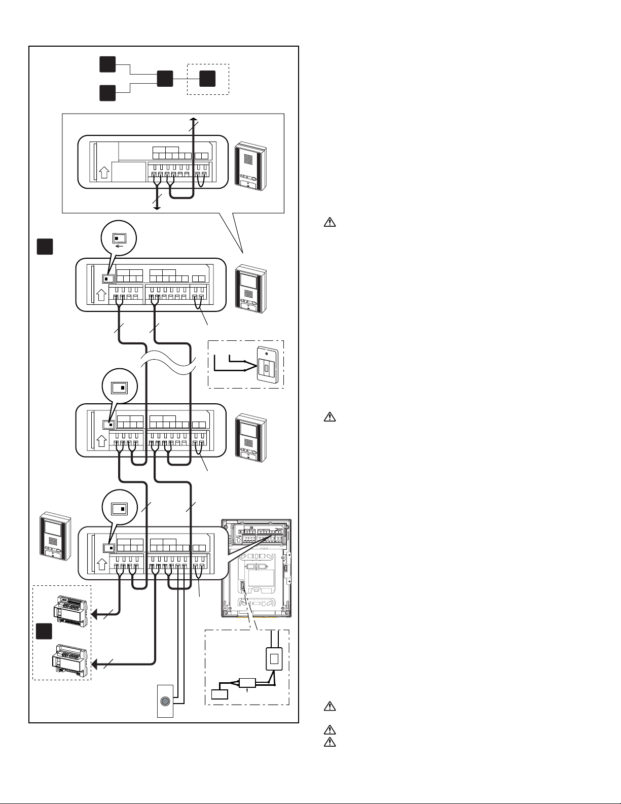
- 19 -
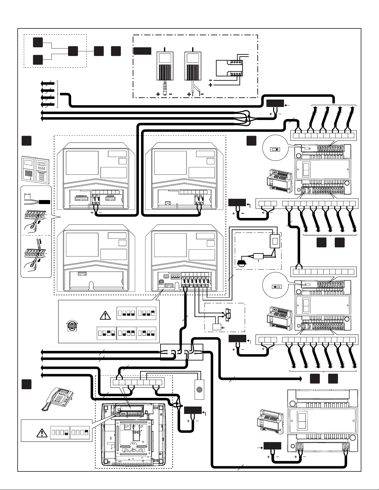
Standard System (2) Station-to-Station Wiring
[1] Residential station GH-1KD, GH-1AD
• There can be a maximum of 25 stations per trunk.
• For the terminating residential station GH-1KD, set the setting
switch (SW1) to "A".
[2] Short lead
• To use the emergency alarm switch (see 11-7 for details),
disconnect the short lead and connect the switch.
[3] External signaling relay GH-RY
For details, see 4-5.
The separate option connecter is required.
[4] Doorbell button
1. Do not mix station-to-station wiring with homerun wiring.
2. Station-to-station wiring is not possible for GH-1MD.
NP: Non-polarized
Standard System (1)
[1] Entrance Station
[2] Door release timer (set to "M" at time of shipment)
• Set the duration for the door release function when the door
release button is pressed.
[0.5] - [20]: 0.5 secs - 20 secs
[20] - [M]: Activates while the button is pressed.
[3] Setting switch (GH-DA/A)
• SW2: 1: Setting switch for camera entrance station monitoring
function (set to OFF at time of shipment)
ON (Up): Monitored.
OFF (Down): Skipped at time of entrance station monitoring.
• SW2: 2 - 4: Entrance station number setting switch (set to #1 at
time of shipment)
When installing multiple entrance stations, make sure to set
the GH-DA/A ID numbers (SW2).
[4] External signaling relay GH-RY
For details, see 4-5.
[5] Door release relay contact
Less than AC/DC 24 V, 4 A (resistance load)
PT: AC Transformer
[6] Security guard station GH-MK
[7] Setting switch (GH-MK)
• SW1: 1: Password reset switch
Set the password reset switch to ON for 2 seconds or more
during standby will reset the password (set to "∗1111" at time
of shipment).
• SW1: 2, 3: Unused switch
• SW1: 4: Security guard station number setting switch (set to #1
at time of shipment)
When installing two security guard stations, make sure to set
the ID numbers (SW1).
[8] Doorbell button
[9] Power supply PS-2410LC, PS-2410LD, PS-2410DIN
[10] Video Bus control unit GH-VBC (SW: STD)
[11] Video Bus control unit GH-VBC (SW: EXP)
• To use GH-VBC as an extension adaptor, set the setting switch
to "EXP". Connect only "IN1" terminal at input side.
[12] Bus control unit GH-BC
[13] Distribution terminal (junction): Not included
NP: Non-polarized
4-1
4-2
4-2
SW1 A B
IN OUT
R1 R2 R1 R2 C
0.65 10 9
CE K KE
Do not remove the wires (For end users)
SW1
A
B
[1]
[4]
GH-VBC
GH-BC
b
GH-1KD
GH-1KD
GH-1KD
SW1
A
B
SW1
B
A
c
1P
NP
1P
NP
1P
NP
1P
NP
1P
NP
1P
NP
AC
B
GH-RY
[3]
[2]
[2]
[2]
GH-1AD
IN OUT
R1R2 R1R2 C CE K KE
IN OUTIN OUT
R1R2 R1R2B1B2 B1B2 C CE K KE
IN OUTIN OUT
R1 R2R1 R2B1B2B1 B2 C CE K KE
IN OUTIN OUT
R1 R2R1 R2B1B2B1 B2 C CE K KE
1P
NP
1P
NP
R1, R2
b
a
e
c
KEK
Page 20
- 20 -
SW1 A B
IN OUT
R1 R2 R1 R2 C
0.65 10 9
CE K KE
Do not remove the wires (For end users)
4-3
[2]
[1]
[5]
GH-1KD
GH-1KD
GH-4Z
GH-4Z
d
GH-VBC
GH-BC
b
SW1
B
A
SW1
B
A
SW1
B
A
SW1
B
A
1P
NP
1P
NP
1P
NP
1P
NP
1P
NP
1P
NP
1P
NP
1P
NP
1P
NP
1P
NP
1P
NP
1P
NP
1P
NP
1P
NP
AC
B
GH-RY
[4]
[3]
[3]
[3]
[3]
b
a
e
d
R2R1B2B1 R2R1B2B1 R2R1B2B1
R2R1B2B1 R2R1B2B1 R2R1B2B1
GH-4Z
R2R1B2B1 R2R1B2B1 R2R1B2B1
R2R1B2B1 R2R1B2B1 R2R1B2B1
R2R1B2B1 R2R1B2B1 R2R1B2B1
R2R1B2B1 R2R1B2B1 R2R1B2B1
SW1
B
A
SW1
A
B
SW1
A
B
IN OUTIN OUT
R1 R2R1 R2B1B2B1 B2 C CE K KE
IN OUTIN OUT
R1 R2R1 R2B1B2B1 B2 C CE K KE
IN OUTIN OUT
R1 R2R1 R2B1B2B1 B2 C CE K KE
IN OUTIN OUT
R1 R2R1 R2B1B2B1 B2 C CE K KE
GH-1AD
GH-1MD
IN OUT
R1R2 R1R2 C CE K KE
B1 B2 R1 R2 C CE K KE
Do not remove the wires!
GH-4Z
GH-4Z
R1, R2
R1, R2
B1, B2
1P
NP
1P
NP
1P
NP
[2]
GH-1KD
[2]
GH-1KD
[2]
[2]
KEK
Page 21

- 21 -
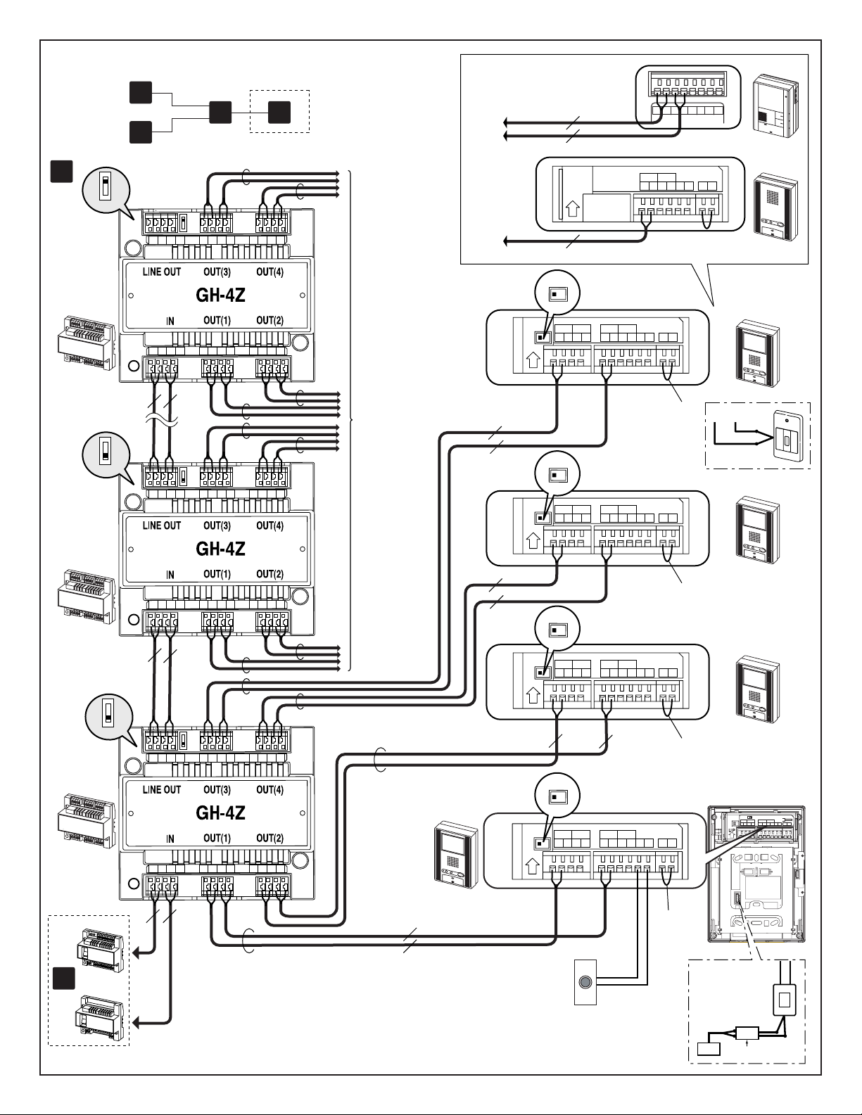
4-3
Standard System (3) Homerun Wiring
[1] 4-way video junction unit GH-4Z
• For the terminating GH-4Z (maximum of 6 units per trunk), set
the setting switch (SW1) to "A".
[2] Residential station GH-1KD, GH-1AD, GH-1MD
• For GH-1KD, set the setting switch (SW1) to "A".
[3] Short lead
• To use the emergency alarm switch (see 11-7 for details),
disconnect the short lead and connect the switch.
[4] External signaling relay GH-RY
For details, see 4-5.
The separate option connecter is required.
[5] Doorbell
Do not mix homerun wiring with station-to-station wiring on
the same trunk line.
NP: Non-polarized
Page 22
- 22 -
1P
1P(Audio)
1P(Video)
1P
GH-BC
GH-BC
GH-BC
GH-VBC
1P
1P
1P
Distribution
point
Distribution
point
Distribution
point
1Px2x5
1Px2
1Px2
1Px2
GH-MK
#2
GH-MK
#2
GH-NS
#2 , #3
GH-NS
#4 - #6
GH-NS
#7 , #8
1Px2 1Px2
Door release
Entrance station
#1
Expanded system
GH-MK #1
Doorbell
GH-MK #1
GH-1KD
Doorbell
GH-1KD
Doorbell
1Px2
1Px2
R1 R2
Trunk line
#2 - #6
SUB1B SUB2A SUB2B
Entrance
#1 - #8
Entrance
#2 - #8
1Px2
1Px2
1Px2
1Px3
PS24
PS24
PS24
PS24
PS24
PS24
PS24
PS24
PS24 PS24
GH-BCX/A GH-VBX
R1 R2R1 R2
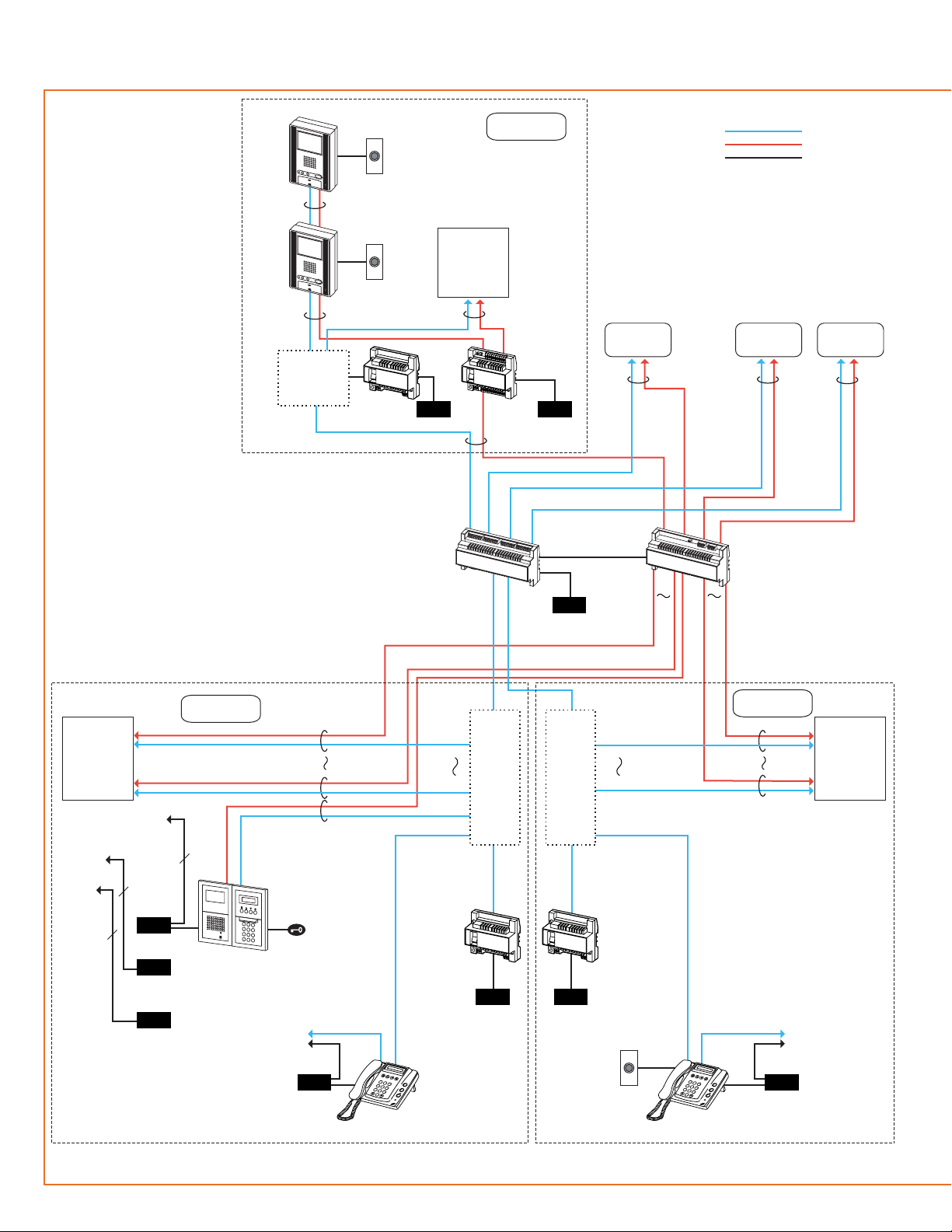
Capacity
16 Entrance stations
4 Security guard stations
500 Residential stations
Trunk line #1
2
B
A
C
1
3
E
D
F
5
K
J
L
4
H
G
I
6
N
M
O
8
U
T
V
7
R
Q
P
S
Y
X
W
Z
9
0
2
B
A
C
1
3
E
D
F
5
K
J
L
4
H
G
I
6
N
M
O
8
U
T
V
7
R
Q
P
S
Y
X
W
Z
9
0
COMMON1
COMMON2
SUB1A
Page 23
- 23 -
AC
GH-NS
#2 , #3
GH-MK
#2
+
-
ELB ELC ELM+RY RY
-
CN2
CN1
GH-DA/A
GH-NS
GH-10K
GH-VA
CN3
CN100
Entrance station #1
CN1 CN3
GH-MK #1
-
C
CE
+
-
AC
1Px2
B1 B2B1 B2 B1 B2
OUT1
IN1
A1 A2
IN2
A1 A2
IN3
A1 A2
IN4
A1 A2
IN5
OUT2 OUT3 OUT4 OUT5 OUT6
+
1Px2
+
-
AC
GH-BC
GH-VBC
+
-
AC
+
+
+
-
AC
GH-BC
+
-
+
-
AC
GH-MK
#1 , #2
GH-BC
+
-
Distribution
point
Distribution
point
Distribution
point
--
STDEXP
B1 B2B1 B2
CN2
SUB1 SUB2
COMMON1 COMMON2
GH-VBX
AC
+
-
SUB1A SUB1B SUB2A SUB2B
COMMON1 COMMON2
GH-BCX/A
GH-1KD
OUT
IN
OUT
IN
C
CE
BA
GH-1KD
OUT
IN
OUT
IN
C
CE
B1
B2
R1
R2
BA
Door bellDoor bell
CN1
Entrance
#1 - #8
Entrance
#2 - #8
SUB1B
COMMON1 COMMON2
SUB1A
SUB2A SUB2B
R1
R2
A1 A2
A1 A2 A1A2 A1 A2 A1 A2 A1 A2
1Px2
1Px2
1Px21Px2
1Px2
+
-
B1 B2
R1 R2R1 R2 R1R2 R1R2
R1 R2
B1 B2B1 B2
R1
R2
R1
R2
R1
R2
R1
R2
B1
B2
B1
B2
B1
B2
R1
R2
R1 R2
B1 B2 B1 B2
Trunk line
#2 - #6
PS24
PS24
PS24
PS24
PS24
PS24
PS24
SW1
ON
1234
SW2
ON
1234
Trunk line #1
1Px2
1Px2
#1 #2
#3 #4
#6
#7 #8
#5
SW2
ON
1
2 3
4
ON
1
2 3
4
ON
1
2 3
4
ON
1
2 3
4
ON
1
2 3
4
ON
1
2 3
4
ON
1
2 3
4
ON
1
2 3
4
A1 A2R1 R2
R1
R2
R1
R2
#1
#2
SW1
ON
1
2 3
4
ON
1
2 3
4
Page 24
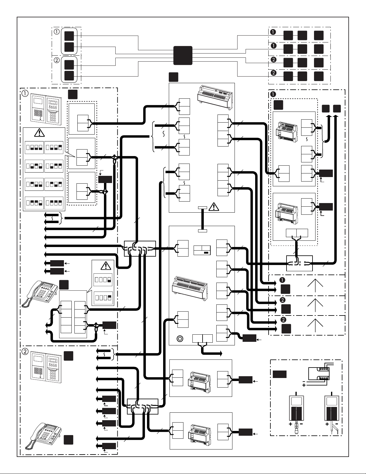
- 24 -
1P
NP
1P
NP
1P
NP
1P
NP
1P
NP
1P
NP
1P
NP
1P
NP
1P
NP
1P
NP
1P
NP
1P
NP
1P
NP
1P
NP
1P
NP
1P
NP
1P
NP
1P
NP
1P
NP
1P
NP
1P
NP
1P
NP
1P
NP
1P
NP
1P
NP
A1
A2
PS-2410LC
PS-2410LD
PS-2410DIN
AC AC
AC
[7]
PS24
GH-VBC
A1
A2
B1
B2
B1
B2
+
–
IN1
OUT6
OUT1
dc
()
GH-BC
+
–
R1
R2
R1
4231
R2
[6]
DP
A
B
b
b
A
b
B
b
PS24
PS24
R1
R2
[5]
GH-BC
+
–
R1
R2
GH-BC
+
–
[5]
PS24
PS24
GHW-LC
GHW-LC
R1
4231
R2
R1
6231
R2
[6]
DP
[6]
DP
45
65
A1
A2
A1
A2
A1
A2
A1
A2
B1
B2
B1
B2
B1
B2
B1
B2
GH-VBX
R1
R2
GH-BCX/A
R1
R2
R1
R2
R1
R2
R1
R2
R1
R2
+
–
COMMON1
COMMON2
SUB1
SUB2
CN2
CN1
COMMON1
COMMON2
SUB1A
SUB1B
SUB2A
SUB2B
[3]
f
[4]
PS24
Power
OFF ON
R1 R2
PC
GH-DA/A
#4 - #6
GH-NS
#1 - #3
GH-MK
#1 - #2
GH-MK
#1 - #2
GH-VA
#1 - #8
1
GH-VA #1
a
[1]
GH-MK #1
e
2
B
A
C
1
3
E
D
F
5
K
J
L
4
H
G
I
6
N
M
O
8
U
T
V
7
R
Q
P
S
Y
X
W
Z
9
0
[2]
#1 #2
#3 #4
#6
#7 #8
#5
SW2
ON
1 2 3
4
ON
1
2 3
4
ON
1
2 3
4
ON
1 2 3
4
ON
1 2 3
4
ON
1
2 3
4
ON
1 2 3
4
ON
1
2 3
4
#1
#2
SW1
ON
1 2 3
4
ON
1 2 3
4
GH-MK
#2
GH-DA/A
#2, #3
GH-NS
#2, #3
GH-VA
#2 - #8
A1
A2
GH-DA/A #1
R1
R2
GH-NS #1
+
-
R1
R2
C
CE
R1
R2
+
–
2
B
A
C
1
3
E
D
F
5
K
J
L
4
H
G
I
6
N
M
O
8
U
T
V
7
R
Q
P
S
Y
X
W
Z
9
0
a
e
PS24
PS24
PS24
PS24
PS24
PS24
GH-NS
#7, #8
GH-NS
#4 - #6
GH-DA/A
#7, #8
GH-DA/A
#1 - #3
GH-DA/A
#4 - #6
GH-DA/A
#7, #8
PS24
PS24
GH-NS
#7, #8
GH-NS
#4 - #6
AC
AC
AC
AC
4-4
12
a
e
a
e
f
b c d
()
b c d
()
b c d
()
b c d
()
A
A
B
B
SUB1A
SUB1B
SUB2A
SUB2B
COMMON1
COMMON2
AC
AC
AC
AC
AC
AC
AC
AC
AC
Page 25
- 25 -
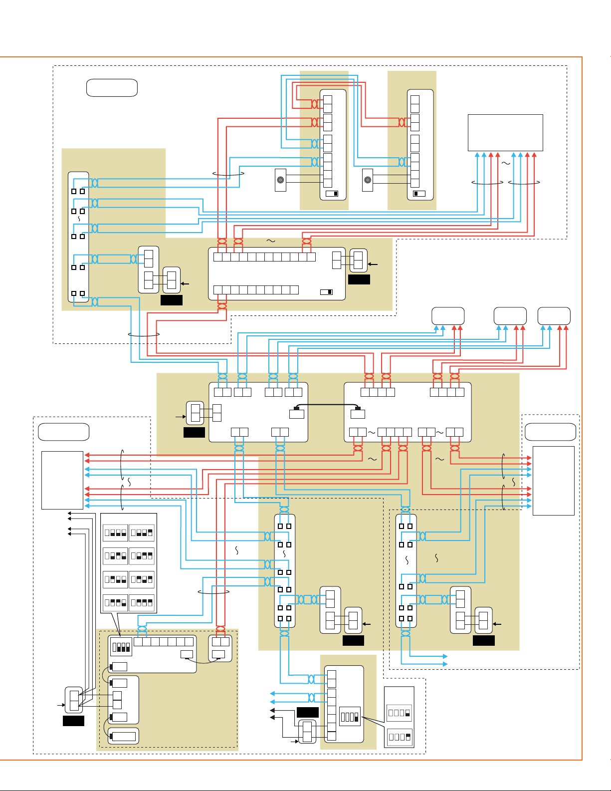
Expanded System
1. Common trunk line: maximum of 2 trunk lines
2. Sub trunk line: maximum of 4 trunk lines
Maximum of 125 units (maximum of 48 units for standard
system)
• The wiring of the sub trunk line is the same as the standard
system. For details, see 4-1 to 4-3.
[1] Entrance Station
• Basic System #1 - #5
• Expanded System (#1 - #8) x 2
When installing multiple entrance stations, make sure to set
the GH-DA/A ID numbers (SW2).
[2] Security guard station GH-MK
• Standard System #1, #2
• Expanded System (#1, #2) x 2
When installing plural security guard stations, make sure to
set the ID numbers (SW1).
[3] Expanded video Bus control unit GH-VBX
Connector cable length: 40 cm (15-3/4")
[4] Expanded Bus control unit GH-BCX/A
For connecting the lift control adaptor GHW-LC, refer to the
GHW-LC Installation & Operation Manual.
[5] Bus control unit GH-BC
[6] Distribution terminal (junction): not included
[7] Power supply PS-2410LC, PS-2410LD, PS-2410DIN
NP: Non-polarized
NOTE: For communication between Entrance station and
Residential station, one each communication path is
available to "COMMON1 - SUB1" and "COMMON2 SUB2". In case of crossover communication such as
"COMMON1 - SUB2" or "COMMON2 - SUB1", it
occupies entire communication path in the system.
4-4
4-5
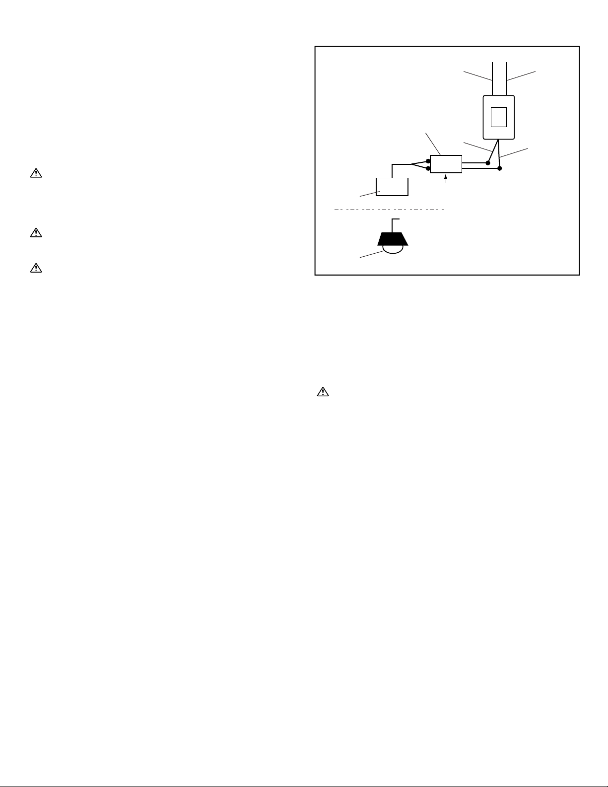
External Signaling Relay Connection
[1] Input wire (blue)
[2] Input wire (white)
[3] Output wire (orange)
[4] Output wire (orange)
[5] Timer (not included)
[6] Buzzer
[7] Entrance light
• GH-RY contact specifications: AC/DC 24 V, 0.5 A ([3], [4])
When connecting GH-RY to GH-1AD, GH-1KD, GH-1MD or
GH-MK, the separate option connector is required.
Please consult your AIPHONE Distributor.
[2][1]
[4]
[3]
[5]
AC
B
GH-RY
[6]
[7]
Page 26
- 26 -
6-1
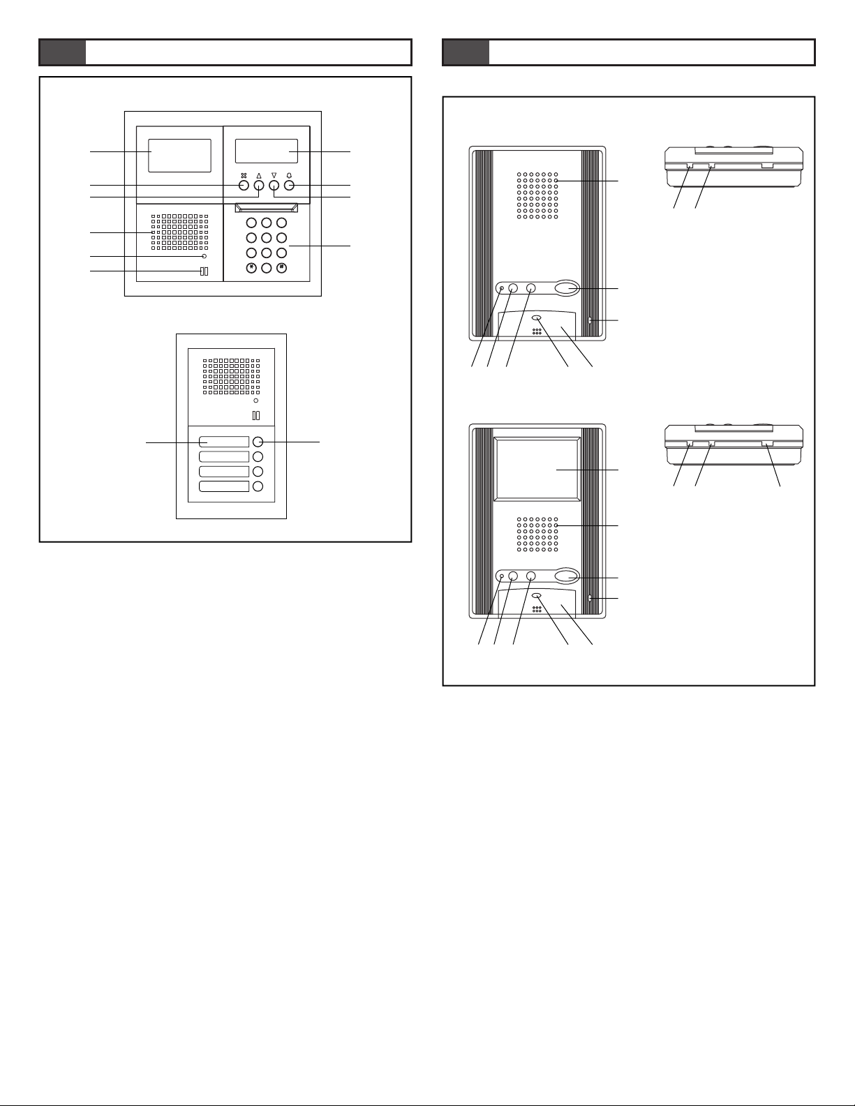
Entrance Station
1. Digital name scrolling entrance station
• Camera module GH-VA
[1] Camera
• Speech module GH-DA/A
[2] Speaker
[3] In Use LED
[4] Microphone
• Digital name scrolling module GH-NS
[5] Display
[6] Cancel button (or set and return)
[7] Back search button (or move cursor to the left)
[8] Forward search button (or move cursor to the right)
[9] Call button (or set and move forward)
• Digital keypad module GH-10K
[10] 10-key (1 - 0, ∗, #)
2. Direct selection
• Switch module GH-SW
[11] Directory card
[12] Call button
Residential station (GH-1AD, GH-1KD)
[1] Speaker
[2] Microphone
[3] Door release button / Monitor button (GH-1KD only)
[4] Talk button
[5] Light button / Security guard station call button
[6] Service button (option)
[7] Talk LED
[8] Call tone off LED
[9] Receive volume control
[10] Call tone volume control
[11] Video monitor 3.5 inch color LCD
[12] Monitor brightness control
5
NAMES (ENTRANCE STATION)
6
NAMES (RESIDENTIAL STATION)
GH-NS
GH-10K
GH-VA
GH-DA/A
[5]
[9]
[8]
[1]
[6]
[7]
[2]
[3]
[4]
[1]
[3]
[2]
[5] [7] [4][6]
[9][10]
[8]
[11]
[3]
[2]
[1]
[5]
[7]
[4]
[6]
[9][10] [12]
[8]
GH-1AD
GH-1KD
2
B
A
C
13
E
D
F
5
K
J
L
4
H
G
I
6
N
M
O
8
U
T
V
7
R
Q
P
S
Y
X
W
Z
9
0
[10]
[12]
[11]
GH-DA/A
GH-SW
1
2
Page 27
- 27 -
6-2
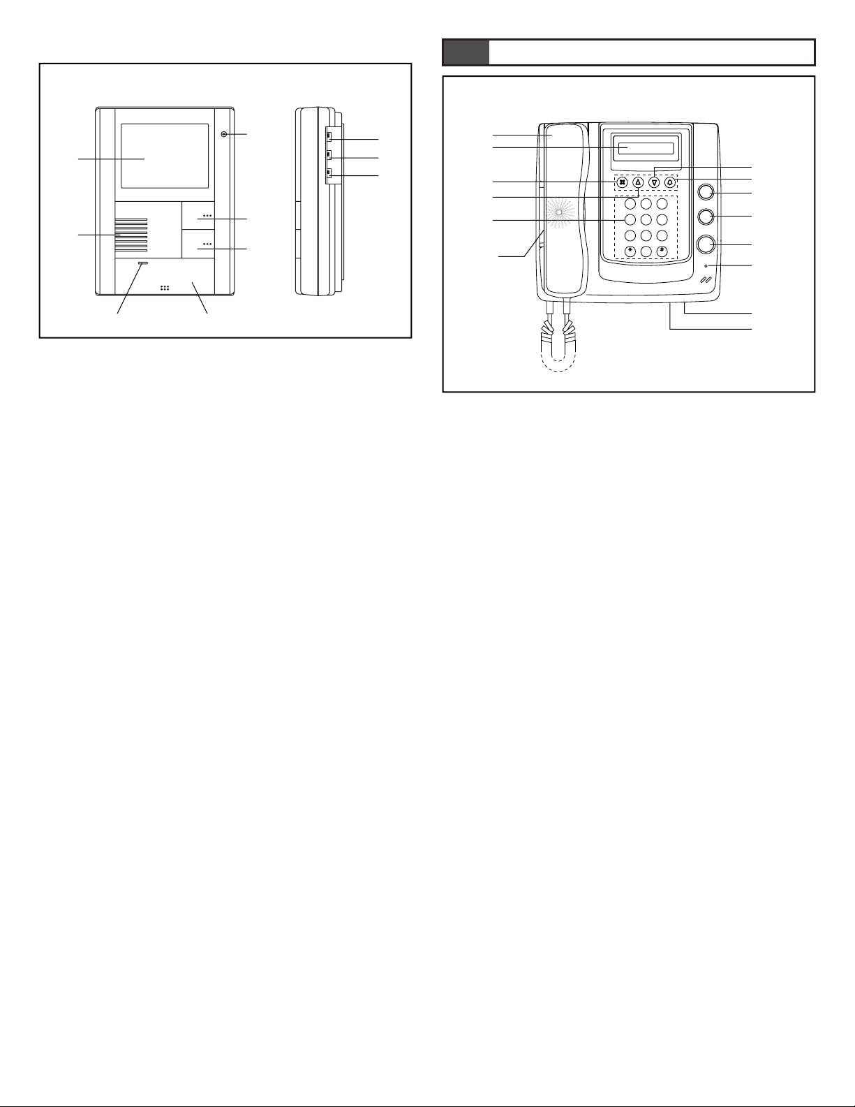
Residential station (GH-1MD)
[1] Video monitor 4 inch black and white CRT
[2] Microphone
[3] Speaker
[4] Light button / Security guard station call button
[5] Door release / Monitor button
[6] Talk button
[7] Talk LED
[8] Monitor brightness control
[9] Receive volume control
[10] Call tone volume control
Security Guard Station
[1] Handset
[2] Display
[3] Cancel button (or set and return)
[4] Back search button (or move cursor to the left)
[5] Forward search button (or move cursor to the right)
[6] Call button (or set and move forward)
[7] 10-key (0 - 9 ∗, #)
[8] Service button (option)
[9] Light button
[10] Door release button
[11] Off hook LED
[12] Speaker
[13] Call tone volume control
[14] RS-232 connection, 3.5 mm port
7
NAMES (SECURITY GUARD STATION)
GH-MK
GH-1MD
[1]
[8]
[2]
[3]
[4]
[7]
[6]
[5]
[9]
[10]
[12]
[13]
[14]
[11]
[1]
[3]
[2]
[4]
[5]
[6]
[7]
[8]
[9]
[10]
2
B
A
C
13
E
D
F
5
K
J
L
4
H
G
I
6
N
M
O
8
U
T
V
7
R
Q
P
S
Y
X
W
Z
9
0
Page 28
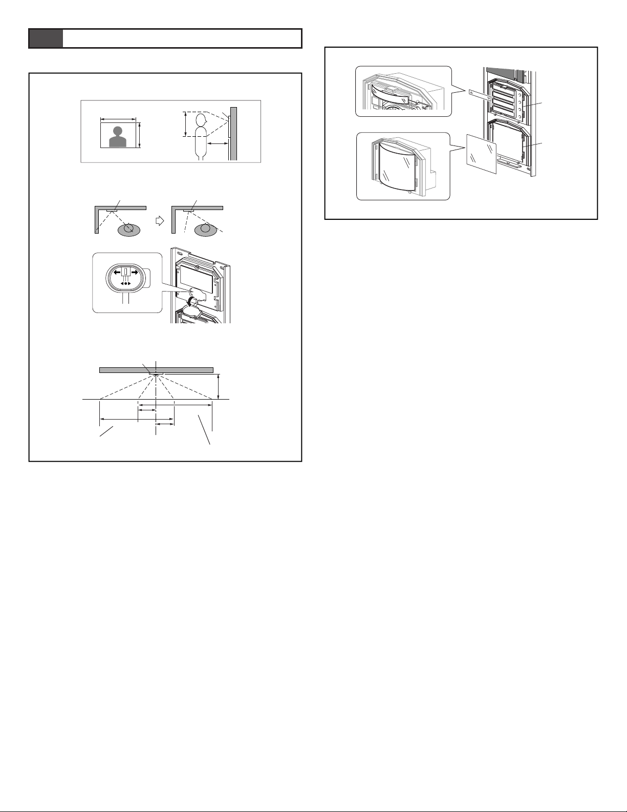
- 28 -
8-1
Adjusting the Camera Angle
1. View from the initial camera position
2. Changing the camera angle
• Remove the rubber cap. Move the lever to the desired position.
∗ Do not forget to reset the rubber cap.
3. Image view area after adjustment
[1] When camera has been adjusted to the left
[2] When camera has been adjusted to the right
8-2
Entering Names and Addresses
• Remove the resident name/address plate or paper by pressing
the left or right end. (Peel off the plastic film.)
• Use a permanent pen to write the resident name and address on
the transparent plate and mount the plate on the module.
8
SETTING UP (ENTRANCE STATION)
1
2
3
GH-VA
113cm
24cm
24cm
50cm
113cm
65cm
GH-VA
95cm
65cm
50cm
GH-VA
GH-VA
GH-SW
GH-AD
[1]
[2]
Page 29
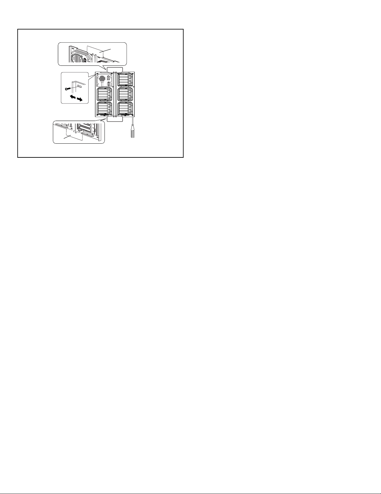
- 29 -
8-3
Making Adjustments with the Mounting Gauge
[1] Mounting gauge
• To mount multiple rows of panels, apply the mounting gauge to
the mounting bracket. While using the mounting gauge to make
adjustments, tighten the screws.
∗ There is a mounting gauge for the built-in back box of GF-2B
and GF-3B.
[1]
[1]
Page 30
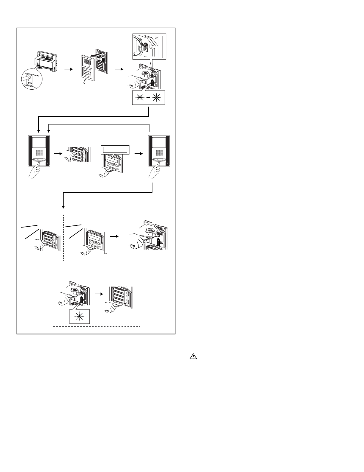
- 30 -
Setting up the System
1. Make sure that all units are installed and wired properly. Turn
on the power switch in GH-BC. When the system includes GHNS, program the resident information (names and room
numbers) in advance. (For details, see 8-5)
2. Loosen the base screw and open and remove the front panel.
3. Set the system to program mode.
• Lift up the rubber cap.
• Press the program switch once. Use any long thin tool, such as
a fine screwdriver.
• The In-Use LED will blink for approximately 15 seconds for
entrance stations with GH-SW and between approximately 6 to
15 seconds for entrance stations with GH-NS.
4. Once the In-Use LED is lit solid, press the talk button of the
first residential station. The corresponding communication
channel will be established.
For GH-MK, lift the handset.
5. For GH-SW, press the (corresponding) call button and release
quickly. (Do not press the button longer than 1 second.) For GHNS, display the assigned room No. and press the call button
(bell symbol). (Do not press the button longer than 1 second.)
An electronic beep will be emitted once.
6. Press the talk button to end. Repeat these steps and program all
residential stations.
For GH-MK, hang up the handset.
∗
If there is a second residential station installed in a single apartment,
program the residential station following the same method detailed
in steps 4 through 6. An electronic beep will be emitted twice. An
electronic sound will be emitted three times for a third residential
station and four times for a fourth residential station.
7. Correcting or changing the settings
• Press and hold down the call button of GH-SW or GH-NS until
you hear a continuous beep. For GH-NS,display the room you
want to correct and reprogram all the residential stations in the
single apartment (following steps 4 and following).
8. Ending programming
•
Push the GH-DA/A program switch. The In-Use LED will go off.
• Replace the cap.
9. Checking the programming
• Pressing the program switch for 5 seconds or more will light up
the In-Use LED.
• In the case of GH-SW, an electronic beep will be emitted once
when the programming was successful. If the programming was
unsuccessful, an alarm beep will be emitted.
• For GH-NS, use the arrow keys or 10-key to select the room
and press the call button. An electronic sound will be emitted
once when the programming was successful. If the
programming was unsuccessful, an alarm sound will be emitted.
• Press the programming switch to end the check.
If power supply is interrupted during programming, the
programmed information might be lost. In such cases, retry
the programming again from the beginning.
NOTES: 1.
Setting up the light button (GH-SW) In Step 3, press the
call button of the assigned GH-SW while the In-Use
LED is blinking (within 15 seconds in program mode),
the light button will be set up. (The assigned call button
cannot be used as the residential call button
simultaneously.) An electronic beep will be emitted once.
2.
If you attempt to setup a fifth residential station when four
residential stations have already been established, an alarm
beep will be emitted. To cancel the communication link,
display the assigned name and press the call button for at
least 3 seconds. A continuous beep will be emitted to verify
the communication link has been cleared.
8-4
123
45 6
78
ON
ON
OFF
SMITH
101
GH-BC
GH-DA/A
GH-SWGH-DA/A
GH-SW
GH-SW
GH-NS
GH-NS
Beeeep
Beeeep
3
Page 31
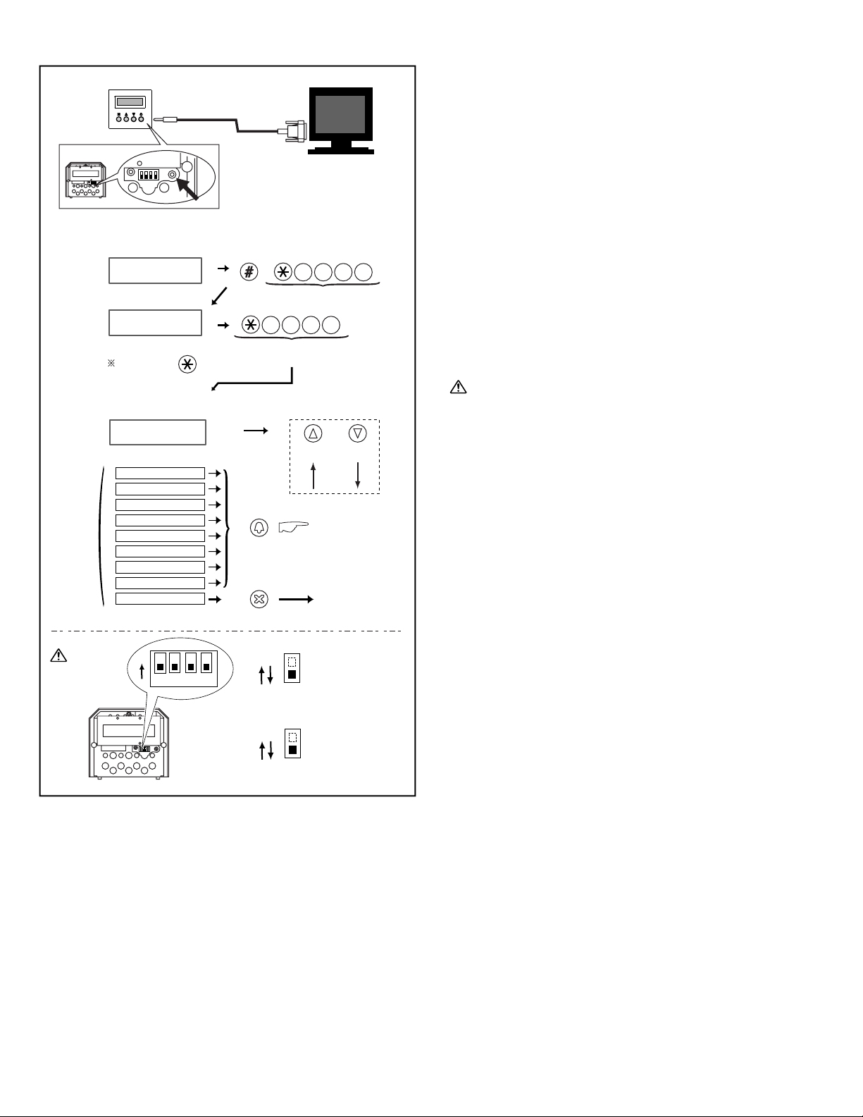
- 31 -
8-5
Programming (GH-NS)
a. Programming with a PC
• You can use a PC to enter data and write in or change resident
names.
• Use the connection cable that comes with GH-NS to connect
your PC to GH-NS.
• In your PC, install the setup tool program from the CD that
comes with the GH-BC.
∗ For information on how to use the setup tool, see the text (.txt)
file that is installed in the same folder as the setup tool (.exe).
Save programmed data and resident information data to your
PC is recommended.
b. Programming with GH-NS and GH-10K
• Confirm that "Welcome" is shown on the Display, indicating
that the system is in standby mode.
∗ You can change the "Welcome" text.
• First, set the system to program mode. (For details, see above.)
∗ Before you begin programming, we recommend that you
register a new exclusive ID code for yourself so that the
system is not accessed by others. (For details, see 8-6.)
If you have forgotten your ID code, set the switch (#1) to ON
for approximately 2 seconds. The ID code will be reset to the
default setting of "∗1111".
NOTE: To display only resident name without room number; Set
the switch (#2) to ON.
b
a
GH-NS
PC
1
ON
1
2 3 4
ON
Enter Program Mode
WELCOME
INITIAL ID CODE
INITIAL ID CODE
DISPLAY
Select Menu & Quit
YOUR OPERATION
RE-ENTER ID CODE
YOUR OPERATION
SELECT LANGUAGE
DISPLAY
MENU
Standby
FORWARD
Scroll
BACKWARD
Go to Menu 1-8
1
2
3
4
5
6
7
8
9
SELECT LANGUAGE
CHANGE ID CODE
ACCESS CODE
RESIDENT INFO
SET TIMER
CHANGE GREETING
TRANSFER DATA
SCROLL SPEED
QUIT
1 1 1 1
ID CODE = + 4 digit
1 1 1 1
DECIDE & BACK
DECIDE & NEXT
2
ON
Page 32
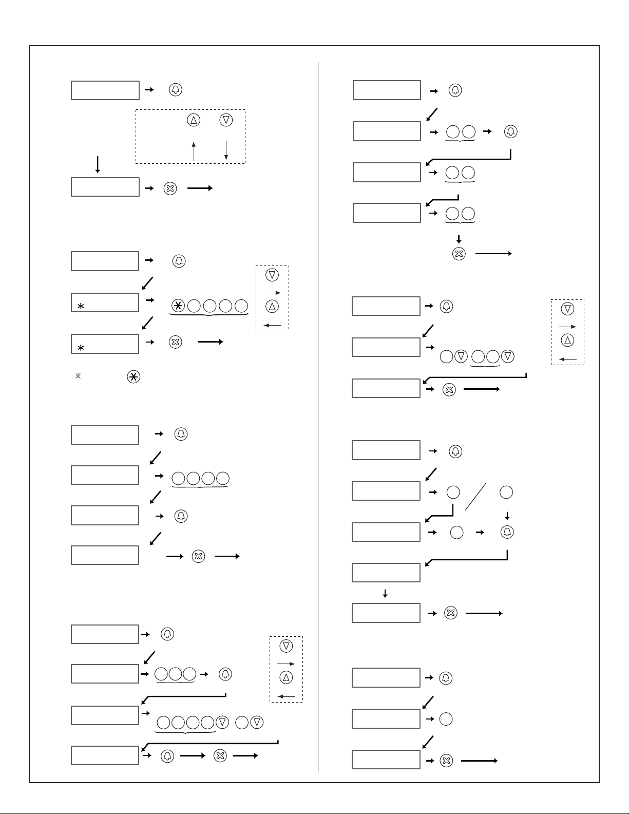
- 32 -
8-6
4
5
6
1
2
3
7
8
ENGLISH
FRANCAIS
DEUTSCH
ESPANOL
NEDERLANDS
SELECT LANGUAGE
ENGLISH
YOUR OPERATION
DISPLAY
MENU
Menu 2
SELECT LANGUAGE
DECIDE & BACK
FORWARD
Scroll
BACKWARD
DECIDE & NEXT
Max. 20 (01)~(20)
programmable
ACCESS CODE
ACCESS CODE (01)
ID 01 (4-digit)
ACCESS CODE (02)
8910
Enter a code.
ACCESS CODE (01)
4567
YOUR OPERATION
DISPLAY
Menu 4
......
7
R
Q
P
S
4
H
G
I
5
K
J
L
6
N
M
O
DECIDE & BACK
DECIDE & NEXT
DECIDE & NEXT
Menu 3
Enter new ID code
CHANGE ID CODE
NEW ID (4-digit)
INITIAL ID
CHANGE ID CODE
1111
CHANGE ID CODE
YOUR OPERATION
DISPLAY
Move cursor
TO RIGHT
TO LEFT
0123
0 1 2
B
A
C
3
E
D
F
ID CODE = + 4 digit
DECIDE & BACK
DECIDE & NEXT
RESIDENT INFO.
ROOM #
1-to 6-digit
101
Enter a name 'SMITH' (example)
......
SM
Enter ROOM #
Menu 5
YOUR OPERATION
DISPLAY
101
SMITH
0 11
DECIDE & BACK
DECIDE & NEXT
DECIDE & NEXT
DECIDE & NEXT
Move cursor
TO RIGHT
TO LEFT
7
R
Q
P
S
7
R
Q
P
S
7
R
Q
P
S
7
R
Q
P
S
6
N
M
O
Menu 6
2-digit (15-99)
PROGRAM TIMER
60
SET TIMER
OPERATION TIMER
15
2-digit (30-99)
YOUR OPERATIONDISPLAY
CALL DURATION
45
2-digit (30-99)
9
Y
X
W
Z
DECIDE & BACK
DECIDE & NEXT
DECIDE & NEXT
3
E
D
F
0
0
0
6
N
M
O
......
Enter " WELCOME TO
..." (example)
CHANGE GREETING
CHANGE GREETING
WELCOME TO ...
WELCOME
DISPLAY
YOUR OPERATION
Menu 7
EW
DECIDE & BACK
DECIDE & NEXT
Move cursor
TO RIGHT
TO LEFT
9
Y
X
W
Z
3
E
D
F
3
E
D
F
Menu 8
1-or-2-digit (1-16)
ENTER UNIT ID#
SECURITY GUARD:
TRANSFER DATA
ENTER UNIT ID#
MAIN ENTRANCE:
YOUR OPERATIONDISPLAY
TRANSFERRING.
DATA TRANSFERRED
1-digit (1-4)
DECIDE & BACK
DECIDE & NEXT
DECIDE & NEXT
0 1
1
1-digit (0-9)
SCROLL SPEED
SCROLL SPEED
8
QUIT
DISPLAY
YOUR OPERATION
Standby
DECIDE & BACK
DECIDE & NEXT
7
R
Q
P
S
Page 33

- 33 -
8-6
Program Mode (GH-NS)
1. Menu 1: Select language
Choose language to be displayed on GH-NS.
2. Menu 2: Change ID code
Enter new ID code starting with "∗", then 4-digit number.
(Example: ∗1234)
3. Menu 3: Set access code
Enter new 4-digit Access Code. (Example: 1234)
• (0000) cannot be registered as an access code.
• Recommend not to use a simple access code such as (1111).
4. Menu 4: Write in resident information
Register room #s and resident names.
Enter room #s using 1 to 6-digit characters.
Enter resident name (up to 16 characters).
5. Menu 5: Set input timeout timer
Operation Timer: If the operation panel is not operated for a
certain period of time, the system returns to standby mode.
Programmable from 15 to 99 seconds.
Program Timer: If, in Residential Programming mode, the
operation panel is not operated for a certain period of time, it
automatically cancels the programming mode. Programmable
from 30 to 99 seconds.
Call Timer: Call from Entrance panel expires in a certain period
of time. Programmable from 30 to 99 seconds.
6. Menu 6: Change greeting
Enter greeting message (up to 160 characters).
7. Menu 7: Transfer link information
With Expanded System, enter unit ID# for transferring
Entrance stations and Security guard stations as below;
• Entrance station: Connected to same common line -
"programmed ID#" as is. (e.g. transferring to #2: Enter "2"), or
Connected to another common line - "programmed ID# plus
8" (e.g. transferring to #1: 1+8=9, Enter "9")
• Security guard station: Connected to same common line -
"programmed ID#" as is. (e.g. transferring to #2: Enter "2"), or
Connected to another common line - "programmed ID# plus
2" (e.g. #1: 1+2=3, Enter "3")
8. Menu 8: Set the greeting scroll speed
0 = slow, 9 = fast
Page 34
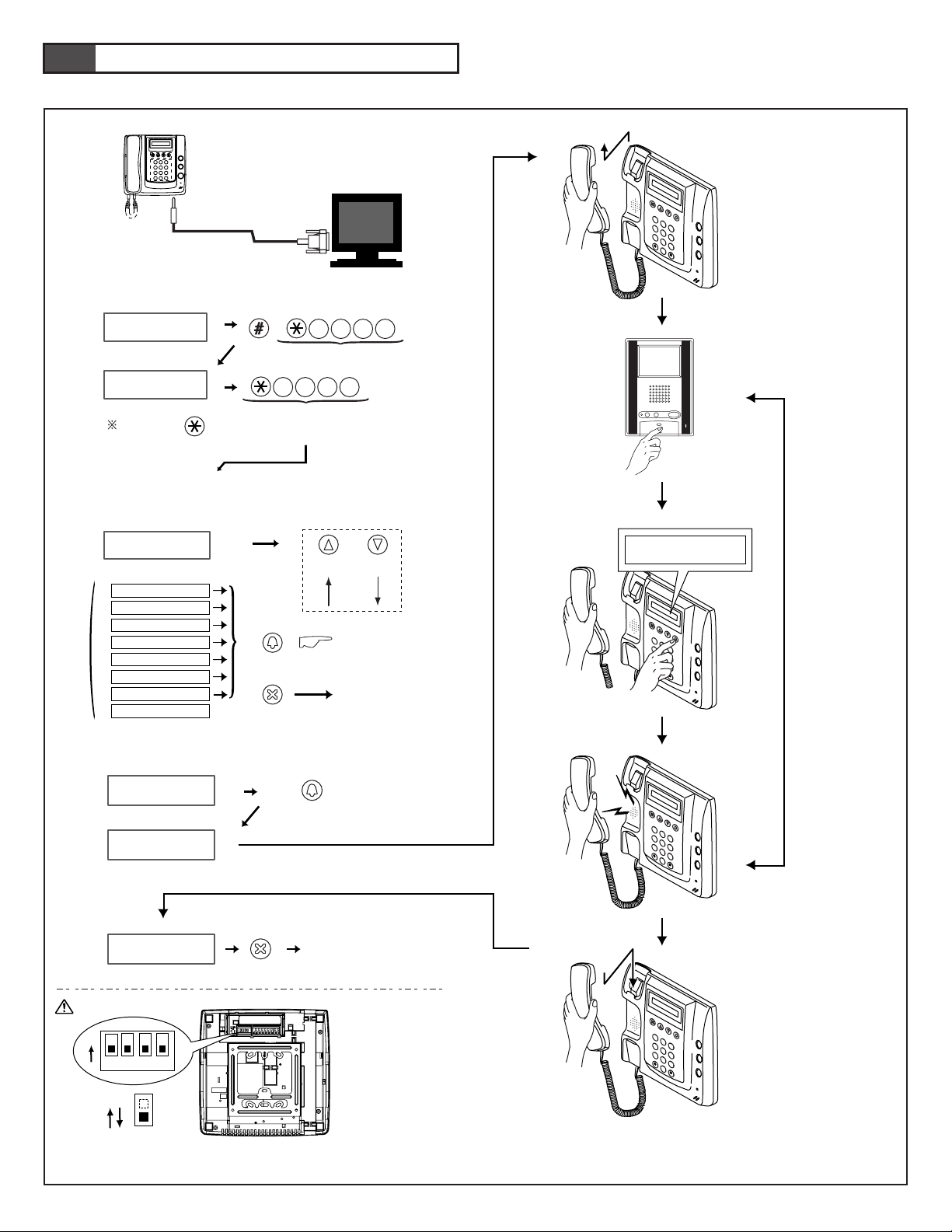
- 34 -
9
SETTING UP (SECURITY GUARD STATION)
GH-MK
Enter Program Mode
Select Menu & Quit
2
B
A
C
1
3
E
D
F
5
K
J
L
4
H
G
I
6
N
M
O
8
U
T
V
7
R
Q
P
S
Y
X
W
Z
9
0
2
B
A
C
1
3
E
D
F
5
K
J
L
4
H
G
I
6
N
M
O
8
U
T
V
7
R
Q
P
S
Y
X
W
Z
9
0
101
SMITH
2
B
A
C
1
3
E
D
F
5
K
J
L
4
H
G
I
6
N
M
O
8
U
T
V
7
R
Q
P
S
Y
X
W
Z
9
0
2
B
A
C
1
3
E
D
F
5
K
J
L
4
H
G
I
6
N
M
O
8
U
T
V
7
R
Q
P
S
Y
X
W
Z
9
0
2
3
4
5
6
AIPHONE
INITIAL ID CODE
INITIAL ID CODE
DISPLAY YOUR OPERATION
RE-ENTER ID CODE
YOUR OPERATION
SELECT LANGUAGE
DISPLAY
MENU
Standby
FORWARD
Scroll
BACKWARD
Go to Menu 1-7
1
2
3
4
5
6
7
8
SELECT LANGUAGE
CHANGE ID CODE
RESIDENT INFO
SET TIMER
PROGRAMMING
TRANSFER DATA
VERIFY PROGRAM
QUIT
1 1 1 1
ID CODE = + 4 digit
1 1 1 1
DECIDE & BACK
DECIDE & NEXT
Beep
b
a
PC
Menu 6
PROGRAMMING<<
PROGRAMMING<<
CONNECTING...
PROGRAMMING<<
CONNECTING...
YOUR OPERATIONDISPLAY
DECIDE & NEXT
DECIDE & BACK
Menu 5
9-1
1
1
ON
1
2 3 4
ON
1
Page 35

- 35 -
9-1
Programming (GH-MK)
• Make sure that all units are installed and wired properly. Turn
on the power switch to GH-BC. Program the resident
information (names and room numbers) in advance.
a. Programming with a PC
• You can use a PC to enter data and write in or change resident
names.
• Use the connection cable that comes with GH-MK to connect
your PC to GH-MK.
• In your PC, install the setup tool program from the CD that
comes with GH-BC.
∗ For information on how to use the setup tool, see the text (.txt)
file that is installed in the same folder as the setup tool (.exe).
Save programmed data and resident information data to your
PC is recommended.
b. Programming with GH-MK
• Confirm that "AIPHONE" is shown on the Display, indicating
that the system is in standby mode.
• First, set the system to program mode. (For details, see 9-2.)
∗ Before you begin programming, we recommend that you
register a new exclusive ID code for yourself so that the system
is not accessed by others. (For details, see 9-2.)
1. Menu 5: Programming
2. Lift the handset (security guard station).
3. Press the talk button on the first residential station. The
corresponding communication channel will be established.
For other GH-MK, lift the handset.
4. Use the search button to display the assigned name and then
press the call button.
5. If an electronic beep is emitted once, the residential station has
been set up successfully. (If an electronic sound is emitted
twice, it is for the second residential station.) Press the talk
button to end the communication channel. Go to the location of
each residential station and program them one by one in
accordance with the programming procedures.
6. Replace the handset (security guard station).
1. If you have forgotten your ID code, set the switch (#1) to
ON for approximately 2 seconds. The ID code will be reset
to the default setting of "∗1111".
2. While data is being entered into the system, the entire
system cannot function (including emergency calls).
NOTE: If you attempt to setup a fifth residential station when
four residential stations have already been established, an
alarm beep will be emitted. To cancel the communication
link, display the assigned name and press the call button
for at least 3 seconds. A continuous beep will be emitted
to verify the communication link has been cleared.
Page 36
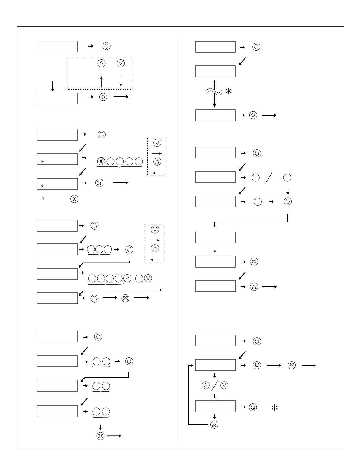
- 36 -
4
1
2
3
ENGLISH
FRANCAIS
DEUTSCH
ESPANOL
NEDERLANDS
SELECT LANGUAGE
ENGLISH
YOUR OPERATION
DISPLAY
MENU
Menu 2
SELECT LANGUAGE
DECIDE & BACK
FORWARD
Scroll
BACKWARD
DECIDE & NEXT
5
Menu 3
Enter new ID code
CHANGE ID CODE
NEW ID (4-digit)
INITIAL ID
CHANGE ID CODE
1111
CHANGE ID CODE
YOUR OPERATION
DISPLAY
Move cursor
TO RIGHT
TO LEFT
0123
0 1 2
B
A
C
3
E
D
F
ID CODE = + 4 digit
DECIDE & BACK
DECIDE & NEXT
RESIDENT INFO.
ROOM #
1-to 6-digit
101
Enter a name 'SMITH' (example)
......
SM
Enter ROOM #
Menu 4
YOUR OPERATION
DISPLAY
101
SMITH
0 11
DECIDE & BACK
DECIDE & NEXT
DECIDE & NEXT
DECIDE & NEXT
Move cursor
TO RIGHT
TO LEFT
7
R
Q
P
S
7
R
Q
P
S
7
R
Q
P
S
7
R
Q
P
S
6
N
M
O
Menu 5
2-digit (15-99)
PROGRAM TIMER
60
SET TIMER
OPERATION TIMER
15
2-digit (30-99)
YOUR OPERATIONDISPLAY
9
Y
X
W
Z
DECIDE & BACK
DECIDE & NEXT
DECIDE & NEXT
3
E
D
F
0
0
CALL DURATION
45
2-digit (30-99)
9
Y
X
W
Z
0
6
7
9-2
1-or-2-digit (1-16)
ENTER UNIT ID#
SECURITY GUARD:
TRANSFER DATA
ENTER UNIT ID#
MAIN ENTRANCE:
YOUR OPERATIONDISPLAY
1-digit (1-4)
DECIDE & NEXT
DECIDE & NEXT
0 1
1
TRANSFERRING.
DATA TRANSFERRED
DECIDE & BACK
QUIT
Menu 7
DECIDE & BACK
Menu 6
PROGRAMMING<<
PROGRAMMING<<
CONNECTING...
PROGRAMMING<<
CONNECTING...
YOUR OPERATIONDISPLAY
DECIDE & NEXT
DECIDE & BACK
101
SMITH
VERIFY PROGRAM
VERIFYING...
YOUR OPERATIONDISPLAY
DECIDE & NEXT
DECIDE & NEXT
DECIDE & BACK DECIDE & BACK
Standby
DECIDE & BACK
Page 37

- 37 -
9-2
Program Mode (GH-MK)
1. Menu 1: Select language
Choose language to be displayed on GH-MK.
2. Menu 2: Change ID code
Enter new ID code starting with "∗", then 4-digit number.
(Example: ∗1234)
3. Menu 3: Write in resident information
Register room #s and resident names.
Enter room #s using 1 to 6-digit characters.
Enter resident name (up to 16 characters).
4. Menu 4: Set input timeout timer
Operation Timer: If the operation panel is not operated for a
certain period of time, the system returns to standby mode.
Programmable from 15 to 99 seconds.
Program Timer: If, in Resident Programming mode, the
operation panel is not operated for a certain period of time, it
automatically cancels the programming mode. Programmable
from 30 to 99 seconds.
Call Time: Call from Entrance panel expires in a certain period
of time. Programmable from 30 to 99 seconds.
5. Menu 5: Programming
∗ For the programming procedures, see 9-1.
6. Menu 6: Transfer link information
With Expanded System, enter unit ID# for transferring
Entrance stations and Security guard stations as below;
• Entrance station: Connected to same common line -
"programmed ID#" as is. (e.g. transferring to #2: Enter "2"), or
Connected to another common line - "programmed ID# plus
8" (e.g. transferring to #1: 1+8=9, Enter "9")
• Security guard station: Connected to same common line -
"programmed ID#" as is. (e.g. transferring to #2: Enter "2"), or
Connected to another common line - "programmed ID# plus
2" (e.g. #1: 1+2=3, Enter "3")
7. Menu 7: Link check (for maintenance purposes)
∗ An electronic sound will be emitted once if link is normal. If
the link is abnormal, an alarm sound will be emitted.
Page 38
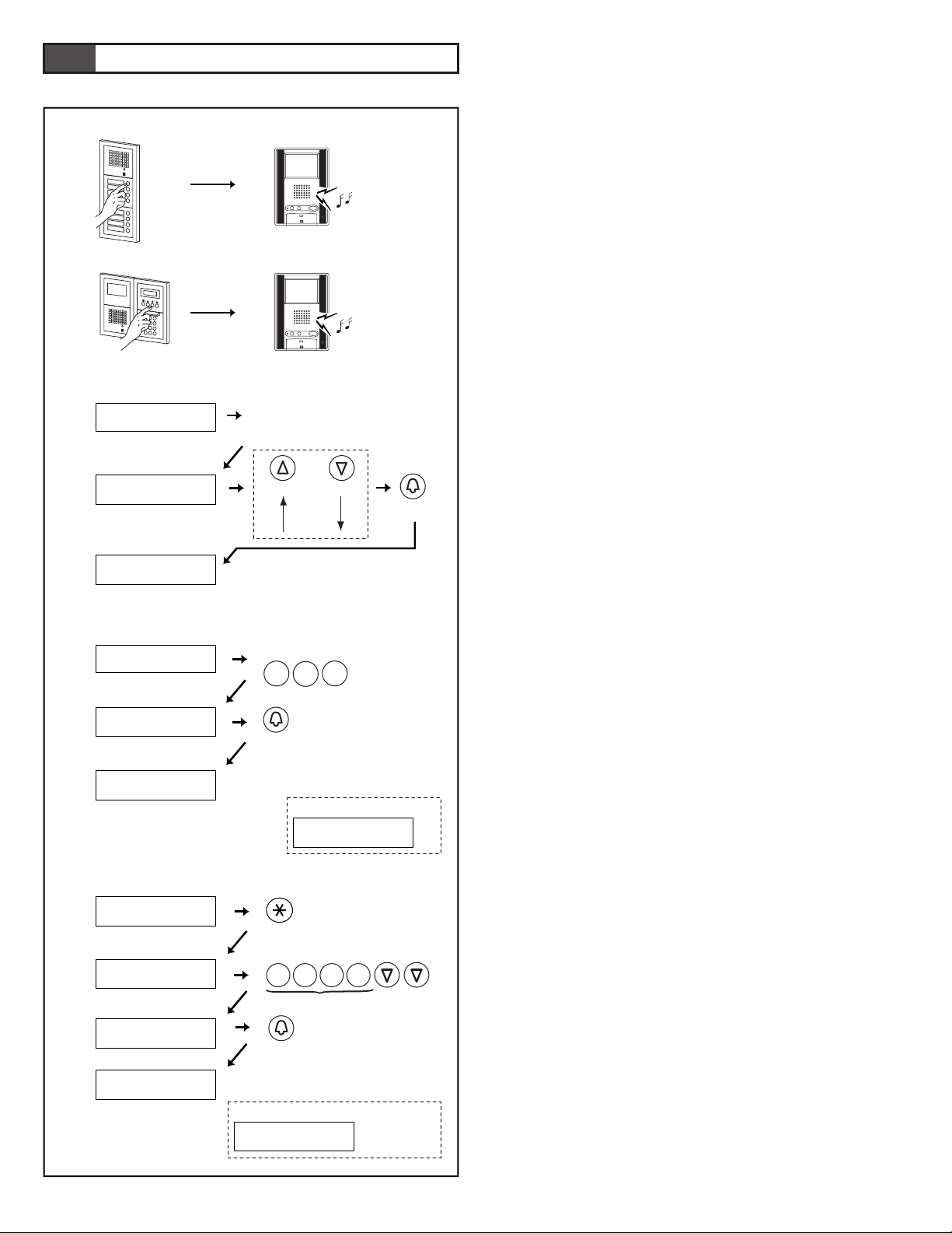
- 38 -
10
OPERATIONS (ENTRANCE STATION)
10-1
Calling a Residential Station
1. Direct Selection GH-SW
• Press the call button for the residence that you want to call. You
will hear a low-volume call tone from the entrance station.
2. Digital name scrolling GH-NS
• Display the resident name you want to call and press the call
button. You will hear a low-volume call tone from the entrance
station.
a. Making a call by name scrolling
b. Making a call by entering the room number
c.
Making a call by entering letters and selecting the corresponding name
NOTE: If you push a call button that has been programmed to
activate a light, the entrance light will turn on. (GH-SW
only.)
1
2
b
c
a
Press button intermittently
or hold down for 2 sec. to
show in succession.
CALLING
SMITH
DISPLAY YOUR OPERATION
FORWARD
Scroll
BACKWARD
CALL
WELCOME
101
SMITH
'SMITH' (example)
CALL
DISPLAY
YOUR OPERATION
ENTER
7
R
Q
P
S
7
R
Q
P
S
7
R
Q
P
S
7
R
Q
P
S
S
...
ENTER A LETTER
WELCOME
101
SMITH
CALLING
SMITH
When there is no name,
(example: A)
NO ENTRY : A
1
0
Press ROOM #.
CALL
1
DISPLAY
YOUR OPERATION
CALLING
SMITH
WELCOME
101
SMITH
When there is no Room #,
NO ENTRY
Page 39
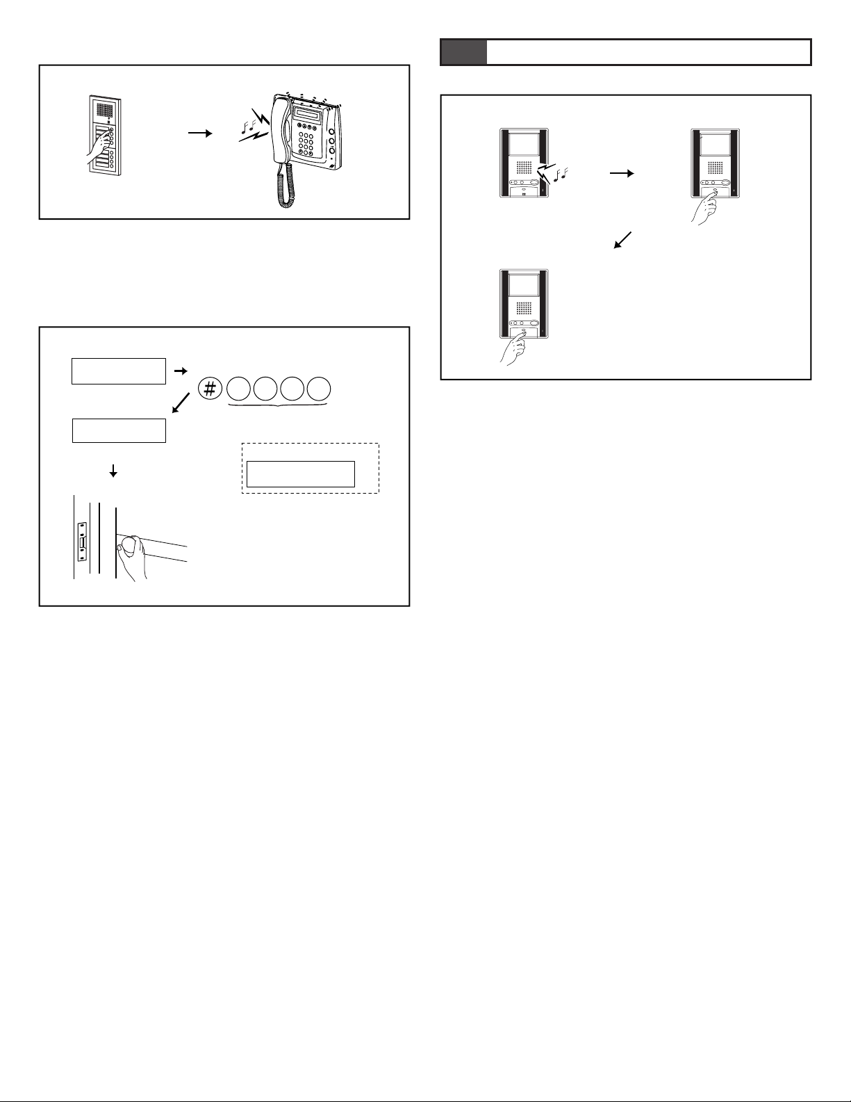
- 39 -
10-2
10-3
Calling the Security Guard Station
Press the call button once. You will hear a low-volume call tone
from the entrance station.
Door Release
1. Enter the access code. (8-6, Menu 3)
2. The door release will be activated at the entrance station.
11-1
Replying to a Call
1. When the call is from an entrance station or security guard
station, the call tone will ring at the residential station for
approximately 10 seconds. An image will be displayed on
monitor residential station.
2. On the residential station, press the talk button within the set
time (see 8-6, menu 5, 9-2, menu 4) to respond and talk
handsfree.
The LED lights when you talk, and goes off as you listen to the
caller.
• If you press the talk button for at least one second while talking
handsfree, a beep will be emitted and you can communicate by
press-to-talk communication.
• In press-to-talk communication, you press the talk button to
talk and release it to listen.
3. When you are done talking, press and hold down the talk button.
∗ The communication will be ended automatically after
approximately 1 minute when handsfree communication is used
at the residential station or after approximately 3 minutes when
handset is used.
NOTE: When "call tone volume control" is put in MUTED
position, "Call tone off LED" on GH-1KD & GH-1AD
and TALK LED on GH-1MD blinks at 5 second intervals.
11
OPERATIONS (RESIDENTIAL STATION)
2
B
A
C
1
3
E
D
F
5
K
J
L
4
H
G
I
6
N
M
O
8
U
T
V
7
R
Q
P
S
Y
X
W
Z
9
0
Enter Access Code 4567
5
K
J
L
4
H
G
I
6
N
M
O
7
R
Q
P
S
ACCESS CODE
DISPLAY
WELCOME
YOUR OPERATION
DOOR OPEN
1
2
When there is no code,
DENIED
12
3
Page 40
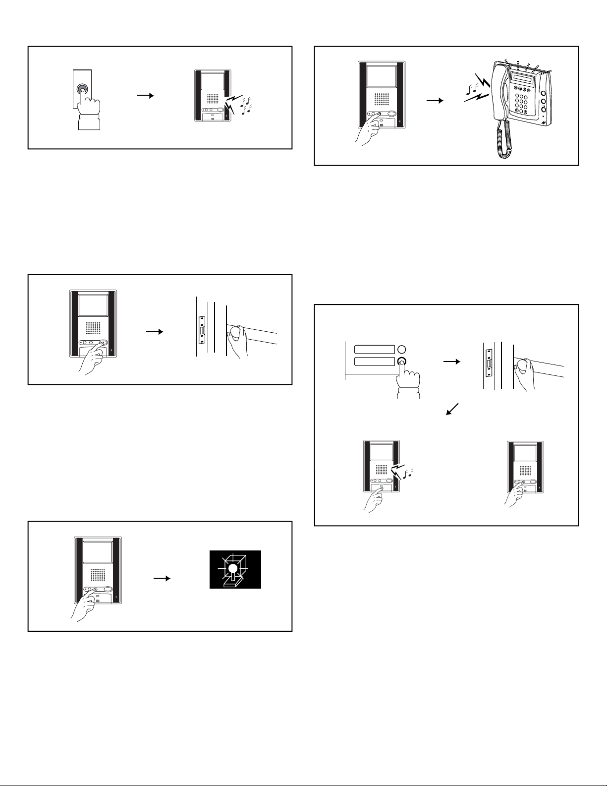
- 40 -
11-3
11-4
Door Release
1. Press the door release button while in communication.
2. The door release function will activate on the entrance station
that is in communication.
∗ Depending on the electric door release system that you use, the
door release may be active only while the door release button is
pressed.
Turning on the Entrance Light
1. Press the light button once while in communication.
2. The outside light of the entrance will turn on for the preset
duration of time. (4 -5)
11-6
Automatic Entry (Doctor Call) Option
1. A visitor presses the call button that has been assigned for
automatic entry.
2. The door is unlocked instantly.
3. The residential station for which the automatic entry function is
set is called. Press the talk button as necessary to respond.
4. Switching the automatic entry function on and off
• Press the light button while holding down the talk button of the
residential station for which this function is set to switch the
function on and off. When the function is on, the Call tone off
LED on GH-1KD & GH-1AD and TALK LED on GH-1MD
will flash at 2.5 second intervals in standby.
11-5
Calling the Security Guard Station
Press the light/security guard station call button on the residential
station. You will hear a low-volume call tone. When the system is
being used for communication, an in-use tone will be heard at the
residential station. (The call is only invalid when a
communication link has not been established.)
11-2
Calling from the Doorbell (at Individual Door)
1. The doorbell button is pushed. A call tone sounds as long as the
button is held down.
2. A different call tone sounds (there is no communication
available).
12
12
1
3
2
4
DOCTOR
2
B
A
C
1
3
E
D
F
5
K
J
L
4
H
G
I
6
N
M
O
8
U
T
V
7
R
Q
P
S
Y
X
W
Z
9
0
12
Page 41
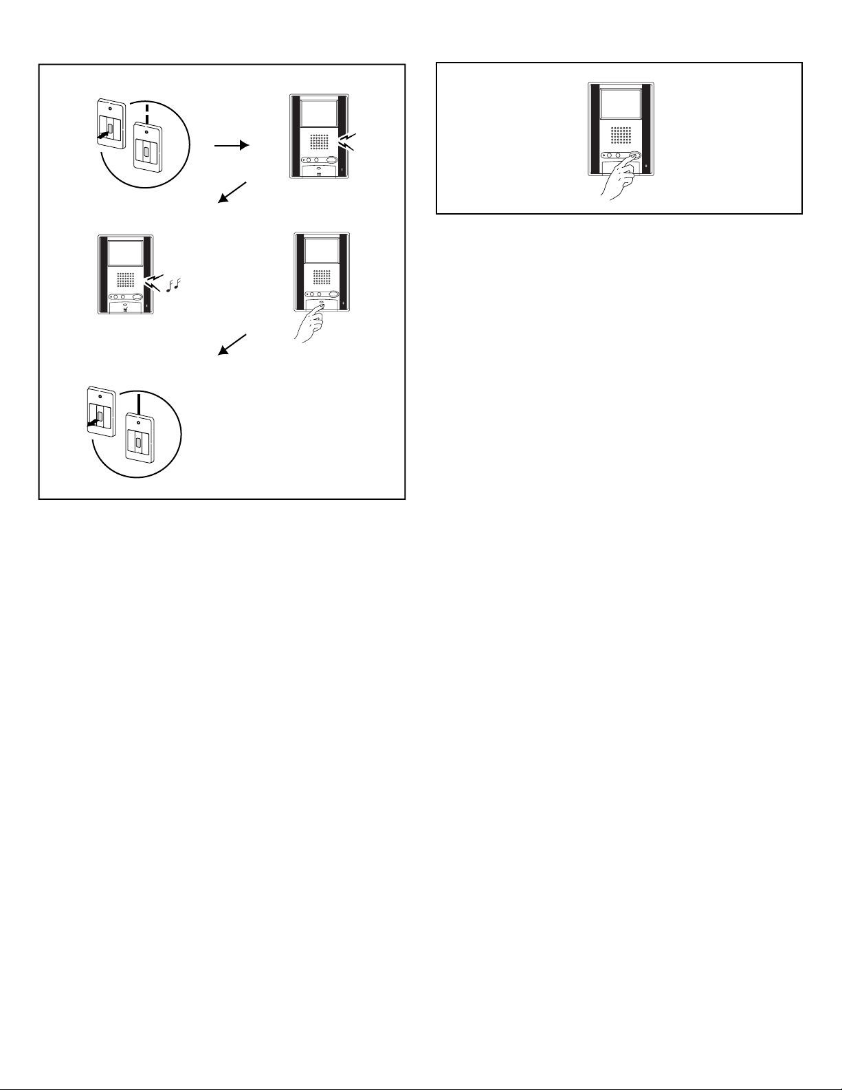
- 41 -
11-7
Emergency Alarm
1. Press and lock the emergency alarm switch (or when there is a
line - off trouble).
2. An alarm will sound from the residential station.
3. When there is a call from the security guard station, the alarm
will change to a standard call tone and sound for approximately
45 seconds.
4. Press the talk button to communicate with the security guard
station. After talking, the emergency alarm will begin to sound
again.
5. Release the lock position of the emergency alarm switch to
return to standby position (restore the system to normal status).
NOTES: 1. On the residential station, the emergency alarm will
be emitted at a loud volume, regardless of the volume
setting.
2. The emergency alarm function can be activated even
when the system is in use. (Alarms can be activated at
the same time by up to 10 residences.)
3. Residential stations within the same residence will be
unable to receive normal calls or doorbell calls while
the emergency alarm is sounding. It is only possible
to respond call from the security guard station.
4. During the emergency alarm, the entrance station
cannot make calls to the residential station that set off
the alarm or to the security guard station.
Monitoring Entrance Stations
With a monitor station, you can monitor entrance stations if you
press the door release button in standby mode. You can switch
between the entrance stations by pressing the door release button.
NOTES: 1. Entrance monitoring is possible for only one
residential station at a time.
2. If you press the talk button while monitoring, you can
communicate with that entrance station.
3. If a call is received while monitoring, monitoring is
terminated.
4. Monitoring lasts for 30 seconds. If you press the door
release button within the 30 seconds, the monitor
screen will switch to the next entrance station and the
30 second monitoring timer will restart.
5.
For information on setting up the monitor, see 4-1 [3].
11-8
1
3
2
4
5
X
Beep,
Beep,
Beep
Page 42
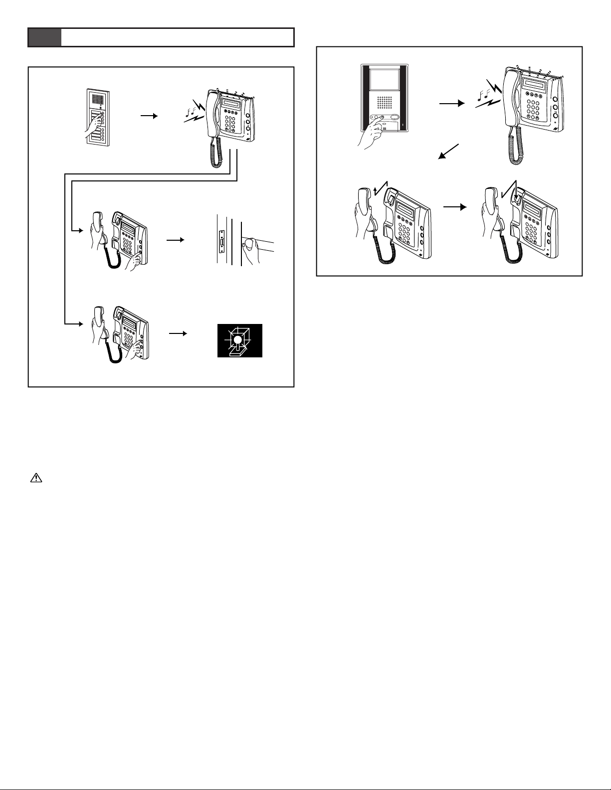
- 42 -
12-1
12-2
Replying to a Call from an Entrance Station
1. When a call is received from an entrance station, a call tone
will sound for approximately 10 seconds at the security guard
station and the entrance station number will be displayed. Lift
the handset and respond. When you are done talking, replace
the handset. Communication ends automatically after
approximately 3 minutes.
With Expanded System, displaying Entrance station's unit ID#
is different by COMMON lines' connection between Entrance
stations and Security guard stations.
Connected to same common line: "programmed ID#" as is.
(e.g. called from Entrance station #1: shown "MAIN
ENTRANCE 01"), or
Connected to another common line: "programmed ID# plus 8"
(e.g. called from Entrance station #1: shown "MAIN
ENTRANCE 09")
2. Press the door release button while in communication.
3. The door release function will activate on the entrance station
that is in communication.
∗ Depending on the electric door release system that you use, the
door release may be active only while the door release button is
pressed.
4. Press the light button once while in communication.
5. The outside light of the entrance will turn on for the preset
duration of time (4-5), based on timer module used.
Replying to a Call from a Residential Station
1. When a call is received from a residential station, a call tone
will sound for approximately 10 seconds at the security guard
station and the room number and resident name will be
displayed. Lift the handset and respond. If a call is not
responded to, a record is kept.
2. Lift the handset to respond.
3. At the end, replace the handset.
∗ The communication will be ended automatically after
approximately 1 minute when handsfree communication is used
at the residential station, or after approximately 3 minutes when
handset is used.
12
OPERATIONS (SECURITY GUARD STATION)
2
45
3
1
2
B
A
C
1
3
E
D
F
5
K
J
L
4
H
G
I
6
N
M
O
8
U
T
V
7
R
Q
P
S
Y
X
W
Z
9
0
2
B
A
C
1
3
E
D
F
5
K
J
L
4
H
G
I
6
N
M
O
8
U
T
V
7
R
Q
P
S
Y
X
W
Z
9
0
23
1
2
B
A
C
1
3
E
D
F
5
K
J
L
4
H
G
I
6
N
M
O
8
U
T
V
7
R
Q
P
S
Y
X
W
Z
9
0
2
B
A
C
1
3
E
D
F
5
K
J
L
4
H
G
I
6
N
M
O
8
U
T
V
7
R
Q
P
S
Y
X
W
Z
9
0
2
B
A
C
1
3
E
D
F
5
K
J
L
4
H
G
I
6
N
M
O
8
U
T
V
7
R
Q
P
S
Y
X
W
Z
9
0
2
B
A
C
1
3
E
D
F
5
K
J
L
4
H
G
I
6
N
M
O
8
U
T
V
7
R
Q
P
S
Y
X
W
Z
9
0
Page 43
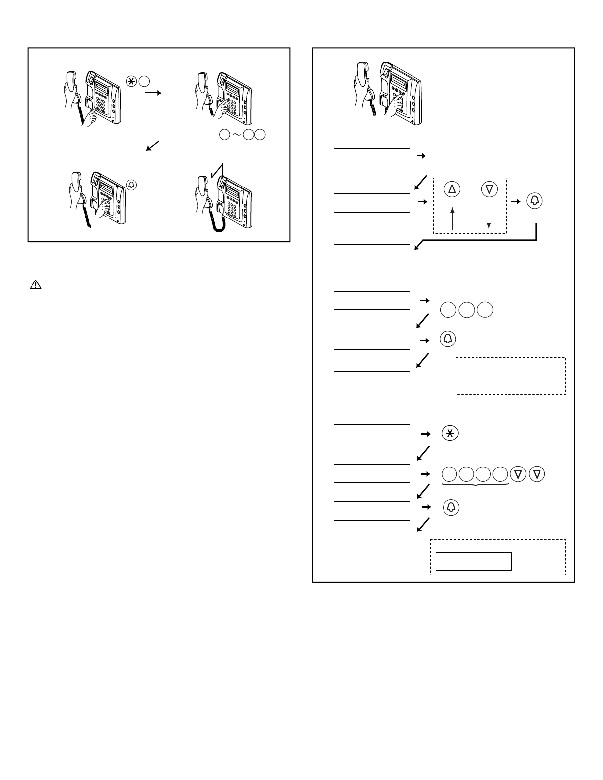
- 43 -
12-3 12-4
Calling an Entrance Station
1. Lift the handset and press the ∗ button and 1 button.
2. Use the 10 key to select the desired entrance station.
With Expanded System, entering Entrance station's unit ID# is
different by COMMON lines' connection between Entrance
stations and Security guard stations.
Connected to same common line: "programmed ID#" as is.
(e.g. calling to Entrance station #1: Enter "1"), or
Connected to another common line: "programmed ID# plus 8"
( e.g. calling to Entrance station #1: 1+8=9, Enter "9")
3. Press the call button to communicate with the entrance station.
If the corresponding entrance station does not exist, "DENIED"
will be displayed. While in communication, you can use the
light button and door release button.
4. When you are done talking, replace the handset.
Communication ends automatically after approximately 3
minutes.
NOTE: ∗ Pressing only buttons is the same as entering letters
when name scrolling and therefore "ENTER A LETTER"
is displayed.
Calling a Residential Station
Lift the handset, display the name and press the call button.
a. Making a call by name scrolling
b. Making a call by entering the room number
c. Making a call by entering letters and selecting the
corresponding name
NOTES: 1. Pressing the search button for approximately 2
seconds will automatically display the resident names
every 0.4 seconds.
2. If both room number 111 and 1111 exist, the resident
name for room 111 will be displayed when 1, 1, 1 is
entered and the resident name for room 1111 will be
displayed if 1 is entered one more time.
1
3
2
4
2
B
A
C
1
3
E
D
F
5
K
J
L
4
H
G
I
6
N
M
O
8
U
T
V
7
R
Q
P
S
Y
X
W
Z
9
0
2
B
A
C
1
3
E
D
F
5
K
J
L
4
H
G
I
6
N
M
O
8
U
T
V
7
R
Q
P
S
Y
X
W
Z
9
0
2
B
A
C
1
3
E
D
F
5
K
J
L
4
H
G
I
6
N
M
O
8
U
T
V
7
R
Q
P
S
Y
X
W
Z
9
0
2
B
A
C
1
3
E
D
F
5
K
J
L
4
H
G
I
6
N
M
O
8
U
T
V
7
R
Q
P
S
Y
X
W
Z
9
0
2
B
A
C
1
3
E
D
F
5
K
J
L
4
H
G
I
6
N
M
O
8
U
T
V
7
R
Q
P
S
Y
X
W
Z
9
0
b
c
a
Press button intermittently
or hold down for 2 sec. to
show in succession.
CALLING
SMITH
DISPLAY YOUR OPERATION
FORWARD
Scroll
BACKWARD
CALL
AIPHONE
101
SMITH
1
0
Press ROOM #.
CALL
1
DISPLAY
YOUR OPERATION
CALLING
SMITH
AIPHONE
101
SMITH
'SMITH' (example)
CALL
DISPLAY
YOUR OPERATION
ENTER
7
R
Q
P
S
7
R
Q
P
S
7
R
Q
P
S
7
R
Q
P
S
S
...
ENTER A LETTER
AIPHONE
101
SMITH
CALLING
SMITH
When there is no Room #,
NO ENTRY
When there is no name,
(example: A)
NO ENTRY : A
6
N
M
O
1
1 1
Page 44
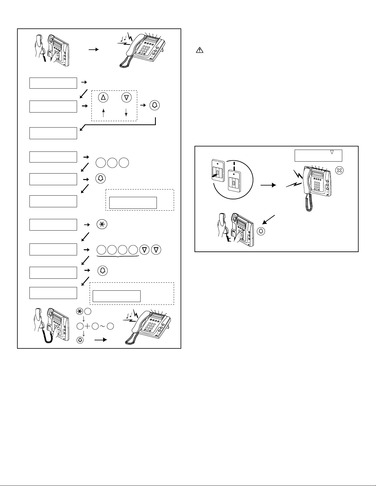
- 44 -
d. Making a call by ID#
Lift the handset and press the "∗" button and "1" button. Press the
"0" button, the security guard station ID (1 -4) button and then the
call button. You will hear a low-volume call tone from the handset.
With Expanded System, entering Security guard station's unit
ID# is different by COMMON lines' connection.
Connected to same common line: "programmed ID#" as is.
(e.g. calling to Security guard station #1: Enter "1"), or
Connected to another common line: "programmed ID# plus 2"
( e.g. calling to Security guard station #1: 1+2=3, Enter "3")
NOTES: 1. Pressing only "∗" button is the same process as
entering letters for name scrolling, therefore "ENTER
A LETTER" is displayed.
2. If the security guard station does not exist, "DENIED"
will be displayed.
12-6
12-5
Calling Another Security Guard Station
Lift the handset, display the name and press the call button.
a. Making a call by name scrolling
b. Making a call by entering the room number
c. Making a call by entering letters and selecting the
corresponding name
NOTES: 1. Pressing the search button for approximately 2
seconds will automatically display the resident names
every 0.4 seconds.
2. If both room number 111 and 1111 exist, the resident
name for room 111 will be displayed when 1, 1, 1 is
entered and the resident name for room 1111 will be
displayed if 1 is entered one more time.
Emergency Call
1. When an emergency alarm switch is locked (or when a wire
disconnection occurs), an alarm sounds at the security guard
station and the word EMERGENCY is flashed with the relevant
room number and resident name on the display. Press the cancel
button to stop the alarm.
2. Lift the handset, check the name on the display and press the
resident call button to communicate with the residential station.
NOTES: 1. If an emergency call is already active on a security
guard station and that station is in communication,
another security guard station cannot interrupt. (An inuse tone will be heard from the handset of the
security guard station.)
2. The security guard station can respond to the
emergency alarm from the residential station, or can
make normal calls to other residential stations.
(However, the name scrolling function will not work
on the security guard station.) Operation is not
possible while the system is in use.
3. The emergency alarm can be activated even when the
system is in use. (Alarms can be activated at the same
time by up to 10 residences.)
4. When a security guard station has received multiple
emergency alarms,an arrow symbol will be shown to
the right of EMERGENCY on the display.
5. When the arrow symbol is displayed, you can use the
search button to select another residential station.
6. Emergency calls while the system is in use can be
made after the other communication is terminated.
1
2
X
2
B
A
C
1
3
E
D
F
5
K
J
L
4
H
G
I
6
N
M
O
8
U
T
V
7
R
Q
P
S
Y
X
W
Z
9
0
2
B
A
C
1
3
E
D
F
5
K
J
L
4
H
G
I
6
N
M
O
8
U
T
V
7
R
Q
P
S
Y
X
W
Z
9
0
EMERGENCY
Beep,
Beep,
Beep
2
B
A
C
1
3
E
D
F
5
K
J
L
4
H
G
I
6
N
M
O
8
U
T
V
7
R
Q
P
S
Y
X
W
Z
9
0
2
B
A
C
1
3
E
D
F
5
K
J
L
4
H
G
I
6
N
M
O
8
U
T
V
7
R
Q
P
S
Y
X
W
Z
9
0
1
0 4
H
G
I
1
CALL
2
B
A
C
1
3
E
D
F
5
K
J
L
4
H
G
I
6
N
M
O
8
U
T
V
7
R
Q
P
S
Y
X
W
Z
9
0
b
c
d
a
Press button intermittently or hold
down for 2 sec. to show in succession.
CALLING
SECURITY GUARD A
DISPLAY YOUR OPERATION
FORWARD
Scroll
BACKWARD
CALL
AIPHONE
001
SECURITY GUARD A
1
0
Press ROOM #.
CALL
0
DISPLAY
YOUR OPERATION
CALLING
SECURITY GUARD A
AIPHONE
001
SECURITY GUARD A
'SECURITY GUARD A' (example)
CALL
DISPLAY
YOUR OPERATION
ENTER
7
R
Q
P
S
7
R
Q
P
S
7
R
Q
P
S
7
R
Q
P
S
S
...
ENTER A LETTER
AIPHONE
001
SECURITY GUARD A
CALLING
SECURITY GUARD A
When there is no Room #,
NO ENTRY
When there is no name,
(example: A)
NO ENTRY : A
2
B
A
C
1
3
E
D
F
5
K
J
L
4
H
G
I
6
N
M
O
8
U
T
V
7
R
Q
P
S
Y
X
W
Z
9
0
Page 45
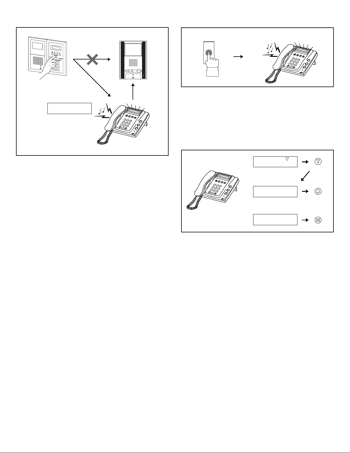
- 45 -
12-812-7
Reception mode
Setting
While in standby mode, press "∗", "1" and "∗" on a security guard
station to display "RECEPTION MODE". In this mode, you can
intercept a call from an entrance to a tenant, and transfer the calls
directly to the security guard station. Press "∗", "1" and "∗" again
to cancel the setting.
NOTES: 1. If there are multiple security guard stations, you can
make and cancel the transfer setting on any security
guard station to switch the setting for the system
overall.
2. Calls from an entrance station are transferred to all
security guard stations that are linked to the
corresponding residential station. The call tone
sounds on all security guard stations at the same time.
3. A call to a residential station that is not linked to a
security guard station will result in a call to the
residential station directly.
Operation
1. In "RECEPTION MODE", all of the calls from entrance
stations to residential stations are transferred to security guard
stations. Tone rings and entrance number, called room number
& name are displayed.
2. Lift the handset, and communicate with entrance station.
3. When transferring the call to called residential station, press
CALL button.
4. After communication with residential station, hang up handset
to establish the communication between caller entrance station
and called residential station.
Calling from the Doorbell Button
1. The doorbell button is pushed. A call tone sounds as long as the
button is held down.
2. A different call tone sounds (there is no communication
available).
12-9
Missed call
1. If a security guard station fails to respond to a call from a
residential station, "MISSED CALL" is displayed on the
display. Press the search button to display the room number and
name that made the call.
2. When the room number and name is displayed, lift the handset
and press the call button to call the residential station or the
security guard station that is displayed.
3. When the room number and name is displayed, press the cancel
button to delete the displayed record. Other records will not be
deleted.
NOTES: 1. The security guard station can hold up to 20 missed
calls.
2. A record of answered calls is not kept.
E01 101
SMITH
2
B
A
C
1
3
E
D
F
5
K
J
L
4
H
G
I
6
N
M
O
8
U
T
V
7
R
Q
P
S
Y
X
W
Z
9
0
12
2
B
A
C
1
3
E
D
F
5
K
J
L
4
H
G
I
6
N
M
O
8
U
T
V
7
R
Q
P
S
Y
X
W
Z
9
0
2
B
A
C
1
3
E
D
F
5
K
J
L
4
H
G
I
6
N
M
O
8
U
T
V
7
R
Q
P
S
Y
X
W
Z
9
0
MISSED CALL
101
SMITH
101
SMITH
DECIDE & BACK
DECIDE & NEXT
1
2
3
Page 46

- 46 -
Technical precautions
• Operating temperature: Entrance Station: -10 °C to 60 °C
(14 °F to 140 °F)
Residential Station: 0 °C to 40 °C
(32 °F to 104 °F)
Security Guard Station:0 °C to 40 °C
(32 °F to 104 °F)
Control Unit: 0 °C to 40 °C
(32 °F to 104 °F)
• Mounting location: Do not install the entrance station in a
place where there would be a bright
light behind a visitor (or where there
would be a bright background) or in a
place where the camera lens would be
directly exposed to sunlight or a bright
light.
• Rain hood (option): Although the entrance station is
weather resistant, it is recommended
that it not be directly exposed to
weather conditions. The rain hood (GFH) can be installed to protect the
entrance station from rainfall.
• Post-replacement setup: After all wiring is completed and the
residential station has been replaced,
turn off the power to GH-BC
temporarily and then turn it back on.
Next, reprogram the relevant residential
station.
• Operation: When an entrance station is calling a
residential station, the call tone from
the doorbell button will not sound.
• Cleaning: Clean the units with a soft cloth
dampened with a neutral household
cleanser. Never use an abrasive cleanser
or cloth.
• Repair requests: When units do not operate properly,
request a qualified technician for repairs.
Specifications
• Power supply:
DC 24V supplied by PS-2410LC, PS-2410LD, PS-2410DIN
(for each GH-BC, GH-VBC, GH-NS/10K, GH-MK, GH-BCX/A)
• Current consumption:
GH-BC: 0.9 A, GH-VBC: 0.9 A, GH-NS: 0.13 A,
GH-MK: 0.18 A, GH-BCX/A: 0.45 A
• Call tone:
There are three different types of call tones:a call tone for the
entrance station, a call tone for the security guard station and
a call tone for the doorbell button.
• Communication path: Single path, non-open
• Communication:
Voice-actuated communication (or press-to-talk communication)
• Door release:
Connecting terminals: Between ELM-ELC (N/O) and ELBELC (N/C)
Specifications: less than 4A (resistance load), AC/DC 24V,
dry closure contact for door release
• Wiring: Two single-pair cable
• Type of cables:
Pair cable (solid wire not stranded), polyethylene insulated,
diameter 0.65 ~ 1.0 mm
• Dimensions:
GH-1MD: 160 (W) x 210 (H) x 55.5 (D) mm
(6-5/16 x 8-1/4 x 2-3/16 inch)
GH-1AD: 125 (W) x 175 (H) x 32 (D) mm
(4-15/16 x 6-7/8 x 1-1/4 inch)
GH-1KD: 125 (W) x 175 (H) x 32 (D) mm
(4-15/16 x 6-7/8 x 1-1/4 inch)
GH-BC: 122.5 (W) x 108.5 (H) x 61 (D) mm
(4-13/16 x 4-1/4 x 2-3/8 inch)
GH-VBC: 122.5 (W) x 108.5 (H) x 61 (D) mm
(4-13/16 x 4-1/4 x 2-3/8 inch)
GH-4Z: 122.5 (W) x 108.5 (H) x 61 (D) mm
(4-13/16 x 4-1/4 x 2-3/8 inch)
GH-MK: 215 (W) x 210 (H) x 69 (D) mm
(8-7/16 x 8-1/4 x 2-3/4 inch)
GH-BCX/A: 210 (W) x 108.5 (H) x 61 (D) mm
(8-1/4 x 4-1/4 x 2-3/8 inch)
GH-VBX: 210 (W) x 108.5 (H) x 61 (D) mm
(8-1/4 x 4-1/4 x 2-3/8 inch)
Entrance Station
2 module, 2 row panel: 270 (W) x 225 (H) x 16 (D) mm
(10-5/8 x 8-7/8 x 5/8 inch)
(Box depth: 44mm (1-3/4"))
3 module, 1 row panel: 135 (W) x 320 (H) x 16 (D) mm
(5-5/16 x 12-5/8 x 5/8 inch)
(Box depth: 44mm (1-3/4"))
• Weight:
GH-1MD: Approx. 980 g (2.2 lbs.)
GH-1AD: Approx. 330 g (0.7 lbs.)
GH-1KD: Approx. 400 g (0.9 lbs.)
GH-BC: Approx. 450 g (1.0 lbs.)
GH-VBC: Approx. 250 g (0.6 lbs.)
GH-4Z: Approx. 190 g (0.4 lbs.)
GH-MK: Approx. 900 g (2.0 lbs.)
GH-BCX/A: Approx. 370 g (0.8 lbs.)
GH-VBX: Approx. 370 g (0.8 lbs.)
13
TECHNICAL PRECAUTIONS
14
SPECIFICATIONS
Page 47
- 47 -
AIPHONE CO., LTD., NAGOYA, JAPAN
AIPHONE CORPORATION, BELLEVUE, WA, USA
AIPHONE S.A.S., LISSES-EVRY, FRANCE
http://www.aiphone.com/
This equipment has been tested and found to comply with the limits for a
Class B digital device, pursuant to Part 15 of the FCC Rules. These limits are
designed to provide reasonable protection against harmful interference in a
residential installation. This equipment generates, uses, and can radiate radio
frequency energy, and if not installed and used in accordance with the
instructions, may cause harmful interference to radio communications.
However, there is no guarantee that interference will not occur in a particular
installation. If this equipment does cause harmful interference to radio or
television reception, which can be determined by turning the equipment off
and on, the user is encouraged to try to correct the interference by one or
more of the following measures: • Reorient or relocate the receiving antenna •
Connect the equipment into an outlet on a circuit different from that to which
the receiver is connected. Increase the separation between the equipment and
receiver. • Consult the dealer or an experienced radio/TV technician for help.
Aiphone warrants its products to be free from defects of material and
workmanship under normal use and service for a period of two years after
delivery to the ultimate user and will repair free of charge or replace at no
charge, should it become defective upon which examination shall disclose to
be defective and under warranty. Aiphone reserves unto itself the sole right to
make the final decision whether there is a defect in materials and/or
workmanship; and whether or not the product is within the warranty. This
warranty shall not apply to any Aiphone product which has been subject to
misuse, neglect, accident, or to use in violation of instructions furnished, nor
extended to units which have been repaired or altered outside of the factory.
This warranty does not cover batteries or damage caused by batteries used in
connection with the unit. This warranty covers bench repairs only,and any
repairs must be made at the shop or place designated in writing by Aiphone.
Aiphone will not be responsible for any costs incurred involving on site
service calls. Aiphone will not provide compensation for any loss or damage
incurred by the breakdown or malfunction of its products during use, or for
any consequent inconvenience or losses that may result.
WARRANTY
The object area of (WEEE) is EU.
 Loading...