

Page 1
0AIPHONE
BX-NOO-I 0186
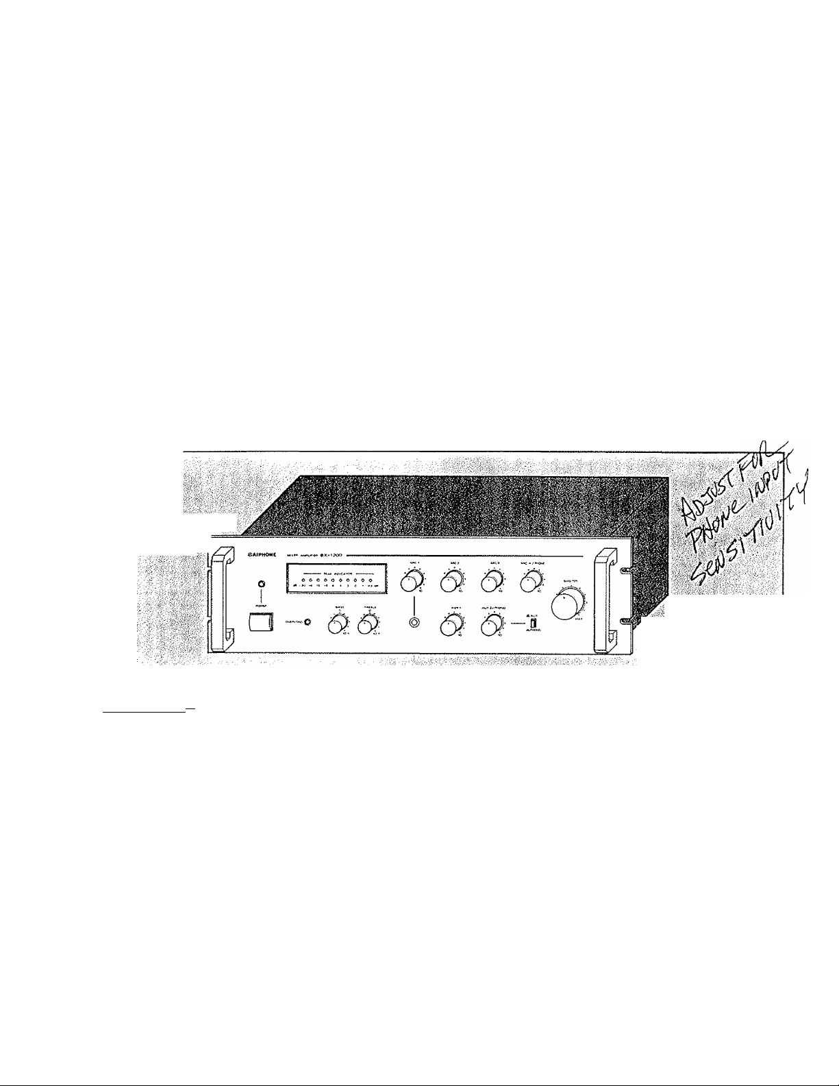
BX SERIES MIXER AMPLIFIER
MODEL: BX-300 (30 watt), BX-600 (60 watt), BX-1200 (120 watt)
-INSTRUCTIONS-
The BX series Mixer Amplifiers, BX-300, -600, -1200 are designed for years of trouble-free use in diverse
commercial and industrial applications. They incorporate the necessary features and functions needed
for use in paging, announcing, intercommunication and background music systems in conjunction with
Aiphone or other communication systems.
Overload protection circuitry prevents damage from either open or short speaker circuits with an attrac
tive LED Peak Meter for visual output monitoring.
A switchable Manual/Automatic Music Muting Circuit offers an adjustable music muting level for back
ground music systems.
(
TLvfVT ■ ■■
( FEATURE^
* Output Overload Protection Circuitry.
* Attractive LED Peak Meter.
* Convenient volume controls including a Master volume control and individual volume controls.
* Individual Bass and Treble tone controls.
* Unique Automatic Music Muting circuit permits adjusting the muting level. (Switchable to manual
muting}.
* 19" rack mountable with handles.
* Frequency response: 50Hz — 15KHz ±1dB.
* Low distortion; Less than 1 % THD at rated output.
* Professional appearance.
* *
WARNING; TO PREVENT FIRE OR SHOCK HAZARD, DO NOT EXPOSE THIS
APPLIANCE TO RAIN OR MOISTURE.
_ 1
Page 2

SPECIFICATIONS
)
Models and Output Power
Frequency Response:
Distortion;
Inputs;
BX-300 . . .
Mic-1
Mic-2
Mic-3
Phone
AUX
Phono
....................Six inputs, Four Channels
8X-300 30 watt rnns. at 1 KHz, AC-120 volt
8X-600 60 watt rms. at 1 KHz, AC*120 volt
BX-1200 120 watt rms. at 1 KHz, AC-1 20 volt
50 - 15,000 Hz ± 1dB
Less than 1 % THD at 1 KHz, rated output
Sensitivity
3mV (-50dB) 20K ohm (unbal.)
0.5mV(-66dB) 600 ohm (balanced)
0.5mV(-66dB) 600 ohm (balanced)“
138mV (-17dB)
lOOmV {-20dB)
2.5mV (-52dB)
Impedance
600 ohm (unbal.)
250Kohm (unbal.)—
50Kohm (unbal.)
Selective inputs
-------
Selective inputs
--------
BX-600,-1200
Mic~1
Mic-2 0.5mV(-66dB)
Mic-3
Mic-4 0.5mV(-66dB)
Phone
AUX-1 100mV (-20dB) 250K ohm (unbal.)
AUX-2 lOOmV (-20dB)
Phono
Outputs:
Noise Level:
Master volume control at "0"
Microphone
Auxiliary..............................................................74dB below rated output
..........................
Sensitivity impedance
3mV (-50dB) 20K ohm (unbal.)
0.5mV(-66dB) 600 ohm (balanced)
138mV (-17dB)
2.5mV (-52dB) 50Kohm (unbal.)—
........................................................
Eight inputs. Six Channels
600 ohm (balanced)
600 ohm (balanced)600 ohm (unbal.)
250K ohm (unbal.)-
4, 8, 16 ohms, 25,70.7 volts balanced
Line output {1v/600ohm)
..............................
80dB below rated output
60dB below rated output
Selective inputs
-2 ™
Page 3

Tone Controls:
Bass..................................................................................± lOdB at 100Hz
Treble
.........................................................
.....................
± lOdB at 10K Hz
)
Indicators:
1-Power Lamp (LED), 1-Overtoad Lamp (LED)
1-Peak indicator (10 LEDs -20, -18, -15, -12, -9, -6, -3, 0,+'i,+36B)
Protection:
AC tine fuse (Primary AC circuit)
Overload protection circuitry (Built-in)
Music Muting Level:
-3 to -40dB adjustable
Connections:
Inputs:
Mic-1
...................................................................
Mic-2
...............
Mic-3,4...............................................................................Screw terminals
Aux, Aux-1,2.....................................................................RCA Phono jacks
Phone
................................................................................
Phono
...............................................................................
Canon XLR {or Switchcraft C3F) (only BX-600,-1200)
Phone jack (front pane!)
Screw terminals
RCA Phono jack
Outputs:
4, 8, 16 ohm ......................................................................Screw terminals
25, 70.7 volt.......................................................................Screw terminals
Line output.........................................................................RCA Phono jack
Others:
Manual Muting
DC 13.2 volt input
AC 120 volt output
Power Supply;
Power Consumption:
...................................................................Screw terminals
.....................................
.................
110- 120V AC, 50/60HZ
13.2V/6.6A DC {only BX-300)
BX-300
BX-600
BX-1200
2 prong AC outlet {unswitched, 100 watt)
Screw terminals (only BX-300)
No signal
18W
26W
32W
Rated output
155W
190W
370W
Ambient Temperature Range:
14“F to 140"F (-10"Cto 60°C)
Page 4
Dimensions (W x H x D):
BX-300 19" X 3/2" X 10-9/16" (482m/m x 88m/m x 268m/m)
BX-600 19" X 5-4/16" X 10-9/16" (482m/m x 132m/m x 268m/m)
BX-1200 19" X 5-4/16" X 10-9/16" (482m/m x 132m/m x 268m/m)
Weight:
BX-300 17.8tbs (8.1 kg)
BX-1200 31.9lbs (14.5 kg)
SPECIFICATIONS ARE SUBJECT TO CHANGE WITHOUT NOTICE.
(^ N AM ES/FUNCTIQNS)
BX-600 25.5lbs(11.6 kg)
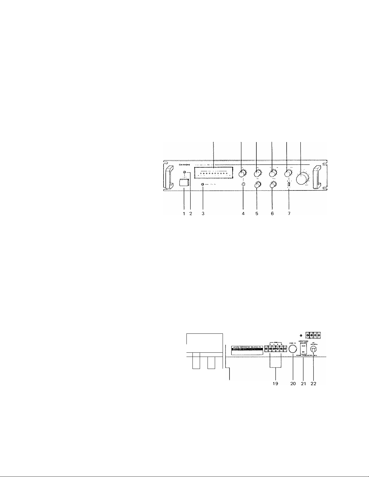
BX-300:
1} Power Switch
2) Power Indicator (LED)
3) Overload Indicator (LED)
4) MIC-1 Input Phone Jack
5) Bass Tone Control
6) Treble Tone Control
7) AUX/PHONO Select Switch
8) Peak Indicator (LED)
9) MiC-1 Volume Control
10) iVllC-2 Volume Control
11) M1C-3/PHONE Volume Control
12) AUX/PHONO Volume Control
13) MASTER Volume Control
14) GROUND Terminal
15) MlC-3 Input Terminals
16) MlC-2 Input Terminals
17) AUTO/MANUAL Muting Control Select Switch
18) Muting Level Control
19) Low impedance Output Terminals
20) AC Fuse (2A)
21) AC Outlet (Max. 100W, unswitched)
22) AC Power Supply Cord
23) PHONO Input Jacks
24) AUX Input Jacks
25) MIC-3/PHONE Select Switch
26) PHONE Input Terminals
27) Manual Muting Control Terminals
28) Constant Voltage Output Terminals (25, 70,7V)
29) Line Output Jack
30) DC 13,2V Power input Terminals
23 24 25 26 27
1
@ ' «$
e*
1
14
15 16 17 18
10 11 12 13
28 29 30
r~pMaaiaMM j ^
;0:-
I
Page 5

BX-600, *1200:
1) Power Switch
2) Power Indicator (LED)
3) Overload Indicator (LED)
4) BASS Tone Control
5} TREBLE Tone Control
6)MIC-1 Input Phone Jack
7}AUX'1 Volume Control
8) AUX-2/PHONO Volume Control
9) AUX-2/PHONO Select Switch
10) PEAK Indicator (LED)
11) MIC-1 Volume Control
12) M lC-2 Volume Control
13) MIC‘3 Volume Control
14) MIC4/PHONE Volume Control
15) MASTER Volume Control
16) GROUND Terminal
17) MIC-2 Input XLR Receptacle
18) MIC-4 Input Terminals
19) MiC-3 Input Terminals
20) M1C4/PHONE Select Switch
21) PHONE Input Terminals
22) AC Fuse (2.5A for BX-600, 5A for BX-1200)
23) AC Outlet (Maxv 100W, unswitched)
24) AC Power Supply Cord
25) PHONO Input Jacks
26) AUX*2 Input Jacks
27) AUX-1 Input Jacks
28) AUTO/MANUAL Muting Control Select Switch
29) Manual Muting Control Terminals
30) Muting Level Control
31) Line Output Jack
32) Low Impedance Output Terminals
33) Constant Voltage Output Terminals
26 27 28 29 30
25
16 17
10
11 12 13
BBS"
14 15
31 32
© @® ©
33
INSTALLATION ^
Unpacking:
Upon receiving unit(s), please inspect for any damage incurred in transit. If damage is found, please notify
your Aiphone Distributor or representative immediately.
Connections:
An AM/FM tuner, cassette player, remote microphone, chime or other high level signal source may be
connected to high impedance inputs with a single-conductor low capacitance shielded cable.
A high impedance microphone with a single conductor shielded cable of 30' to 60' (10 to 20m) length
can be plugged into the MIC-1 input on the front panel.
Page 6

Make certain that all input cables are kept away from speaker cables, power cables and power trans
formers.
Speaker cables must also be kept away from power cables.
Grounding the Unit:
The chassis of the unit must be grounded by using the GROUND terminal located on the back.
The amplifier must be connected to an earth ground such as a cold water pipe or a substitution of the
ground. If additional equipment is installed along with the amplifier, make sure that the additional
chassis are also grounded.
DC Power Connection (only BX-300):
The unit may also be powered by an externa! 12 volt battery or other direct current source with negative
{—) as ground.
Power connection is made at the DC terminal strip on the back panel.
Ventilation:
In order to offset the heat generated by the unît, it is necessary to provide ample ventilation around the
unit-
Avoid blocking or impeding the ventilation holes and slits on the unit.
Locate the unit where it is free from direct sunlight, humidity, dust circulation or vibrations to prevent
any unnecessary problems.
INPUT CONNECTIONS
(J
Microphones:
Three microphone inputs on the BX-300 and four microphone inputs on the BX-600 and BX-1200 are
provided.
They may be used with balanced or unbalanced high impedance (20Kohm) or low impedance (200 ohm)
microphones. An unbalanced microphone with 30' to 60' (10 to 20m) of cable may be used, but results
will depend on the microphone and its characteristics.
MIC-1, MIC-2, MIC-3 and MIC-4:
The MlC-1 input is unbalanced high impedance and is provided with a ka" phone jack located on the
front panel.
MiC-2, -3, -4 inputs are balanced low impedance and all are located on the back panel.
Unbalanced High Impedance Microphone:
Use with single conductor shielded cable.
Unbalanced microphone
Single pole phone plug
Page 7
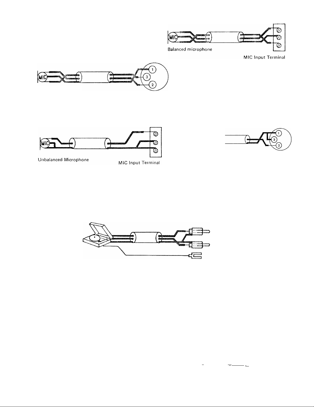
Balanced Low impedance Microphone:
Use with two conductor shielded cable.
Balanced Microphone
Unbalanced Low Impedance Microphone;
Use with single conductor shielded cable.
Canon XLR-M
Unbalanced Microphone
Canon XLR*M
Phonograph:
A magnetic phonograph cartridge may be connected to PHONO input.
A ceramic or crystal cartridge pick-up may be connected to AUX, AUX-1 or AUX-2 input. Use a single
conductor or two conductor shielded cable, and ground the separate ground wire from the player to
GROUND terminal on the back panel.
PHONO
@
Connect to the GND (■&)
terminal of the amplifier
*There are two PHONO jacks (R and L) provided for the connection with stereo player. The R and L
channels will be mixed automatically.
Auxiliary (AUX, AUX-1 & AUX-2):
An AM/FM tuner, tape player, remote microphone, chime, mixer preamplifier or other high level signal
sources may be connected to the AUX, AUX-1 or AUX-2 input.
Use single or two conductor shielded cable.
From unbalanced type AUX, AUX-1, -2
output equipment
From balanced type
output equipment
AUX, AUX-1, -2
L or R
Lor R
From Stereo Type
Output equipment
r\
MIIMII Iiiiuiudiu 1 j II j
-------------
V_
£3-
AUX, AUX1, AUX2
A .
....................
. I^L U---------------------------------------^
Page 8

* There are two jacks (R and L) provided for connection with any stereo signal source. The R and L
channels will be mixed automatically.
Telephone:
A voice signal from the telephone system (600 ohm, unbalanced) may be connected to the PHONE input.
Use single or two conductor shielded cable.
■nSBBSiiflli j
From telephone system
-P
PHONE
NOTE:
The following combination of two inputs cannot be used at the same time. They are selectable using
the select switches located .on the front and back panel.
BX-300 - Either MIC-3 or PHONE, and AUX or PHONO.
— PHONE -t- AUX /Pt-tONO
PHONE —, r™ MIC 3
. • .
m j
©
3 I 2
BACK PANEL
©
PHONO
FRONT PANEL
PHONE
—© T
BX~600, -1200 - Either MIC-4 or PHONE, and AUX-2 or PHONO.
PHONE
BACK PANEL
© ©
AUX 2/PHONO
o~~i
o
©
)
—I I------------PHONE
“ MJC 3
©
■ MIC 4
©
O
3 12 3 12
OUTPUT CONNECTIONS
0
Speaker Output
The amplifier may be used in conjunction with a speaker rated at 4, 8 and 16 ohms or with balanced 25
volt or 70.7 volt constant voltage speaker systems.
Low Impedance Output(4, 8 and 16 ohm):
The 4, 8 and 16 ohm output terminals are provided for the connection of a few large-output speakers.
This applies when a constant voltage speaker system is unnecessary or in case the distance between the
amplifier and the speakers is less than 200' or 60m.
FRONT PANEL
Page 9

it is requested that the total speaker load impedance be correctly matched to the output impedance of
the amplifier for the most efficient transfer of power.
Be sure that total impedance of speakers is above 4, 8 or 16 ohms. However, do not use a speaker rated
at less power than the amplifier is capable of producing, otherwise the speaker will be damaged.
\Z7
/
25 volts and 70.7 volts Output;
—tzi
16f2
0 \
______________
o ^1 y—
-------------
4Q
/ \
_________
4Î2 4Ü.
When It is desired to operate the speaker from a distance of over 200' {60m) from the amplifier and/or
the system requires more than four speakWs, It is recommended that line matching transformers be
used for the speakers to prevent excessive line losses.
This method of load matching is known as the constant voltage distribution system, and eliminates the
calculation of load impedance and series-parallel speaker arrangements. In this method, all speakers are
connected in parallel.
These constant voltage outputs are most convenient for distribution of power when a number of speakers
are installed. Each speaker must have 25 volt or 70.7 volt line transformer with a tap that gives the power
desired for that speaker. The total number of power settings for ail speakers should be equal to the
amplifier power rating or less.
-9 -
Page 10

Line Output:
To operate a booster amplifier or tape recorder, use single conductor shielded cable with an RCA phono
plug from the LINE OUT to the input of the booster amplifier or tape recorder.
This output is subject to ail settings of each input gains, master gains and tone controls.
LINE OUT
to booster amplifier
or tape recorder
OPERATIONS
c
Volume Control Setting:
For an average input signal, the MASTER volume control should be set to the middle. Relative to the
other input levels, it is recommended that the gains or losses be equally divided between individual
controls and the master control.
D
Tone Controls;
The separate tone controls provide boost and alternation of bass and treble response. The flattest res
ponse is obtained when knobs are set to zero "0",
Turn BASS control knob or TREBLE control knob clockwise to raise the appropriate tone level by
approximately + lOdB, turn counter-clockwise to lower tone levetby approximately -lOdB.
Peak Indicator:
Each of the LEDs of the PEAK INDICATOR Panel indicates output level.
When voice or music is amplified, set the volume control knob at the position where the maximum out
put level is below zero "0".
PEAK INDICATOR
o 0
dB -20
18
o o
15 12
O 0 o o o o
9 6 3 0 1 +3 dB
Overload:
If the external load exceeds the rated power, a protection circuit will respond and protect the amplifier
immediately (even If the load is short-circuited). The protective circuit will be activated by loading 1.5
times over the rated output power.
- 10
Page 11

When the OVERLOAD indicator is lit, turn off the POWER and check the output circuit.When proper
operating conditions have been secured, turn the POWER on, and make sure OVERLOAD indicator is
off, otherwise recheck the output circuit.
Music Muting Control:
The voice activated microphone precedence control circuitry offers smooth and natural voice announce
ment.with reduced soft music in the background.
When announcements are made through microphones (MlC-1, MlC-2, MlC-3, MIC-4, PHONE), the
electronic precedence control circuit automatically alternates the level of the background music AM/FM
radio broadcast, music tape, or other sources, allowing you to make announcements which are clear and
more attractive.
The level of the music source is automatically returned to normal when the announcements is finished.
The muting level is adjustable within a range from —3 to —40dB with MUTING LEVEL control located
on the back panel.
The precedence control circuit can also be activated by an external dry contact. The AUTOMATIC and
MANUAL control mode switch is also located on the back panel.
MANUAL MUTING
3
AUTO-
□
MUTING LEVEL
MANU
BX-300
MIN ; MAX
AUTO
“1 r
Q
MANUAL MUTING
BX-600, -1200
MUTING LEVEL
MANU .
MIN I MAX
-11
Page 12

CAUTION: TO PREVENT ELECTRIC SHOCK. DO NOT REMOVE CABINET.
NO USER SERVICEABLE PARTS INSIDE.
REFER SERVICING TO QUALIFIED SERVICE PERSONNEL.
«■**■^^^^^(■*■)(■■*^*^^*■K*****
We at AlPHONE are proud of our products. Our designers and engineers strive to bring you the
finest in sound equipment. Each item has been carefully tested and inspected before leaving our factory.
Properly installed and used, your Aiphone sound system should give years of troublefree service.
We are pleased to offer the following warranty:
UMU AAXAiJi \XJJU lit.tM A U_iAi
WARRANTY
Aiphone warrants its products to be free from defects of material and workmanship under norma!
use and service for a period of one year after delivery to the ultimate user and will repair free of
charge or replace at no charge, should it become defective upon which examination shall disclose
to be defective and under warranty, Aiphone .reserve unto itself the sole right to make the final
decision whether there is a defect in materials and/or workmanship; and whether or not the prod
uct is within the warranty.
This warranty shall not aoply to any Aiphone product which has been subject to misuse, neglect,
accident, or to use in violation of instructions furnished, nor extended to units which have been
repaired or altered outside of the factory.
This warranty does not cover batteries or damage caused by batteries used in connection with the
product.
This warranty covers bench repairs only, and arty repairs must be made at the shop or place des
ignated in writing by Aiphone. Aiphone will not be responsible for any costs incurred involving on
site service calls.
Aiphone Corporation, Bellevue, Washington 98005
BX-NOO-l 0186
Printed in Taiwan
- 12-
 Loading...