

Page 1
AX Series Audio-Video Adaptor for 3rdParty Transmission Equipment
- INSTRUCTIONS -
The AXW-AVT is designed to allow connection of a standard AX-series audio video door station (or audioonly IE-series door station) via the AXW-AVT, conditioning the signal for use with 3
equipment (Ethernet). External video input is provided at adaptor to allow 3
rd
rd
party transmission
party camera input, output to
recording devices, etc. A motion detector or other activation device can be connected to the Sensor input to
trigger door / camera activation. The units also feature a relay output to trigger an external device, such as a
DVR or video switcher local to the AXW-AVT whenever the audio and/or video is active. Alternatively, the
AXW-AVT can be used to adapt an AX-series audio video door station to a standalone third party device
(video server, network DVR, etc).
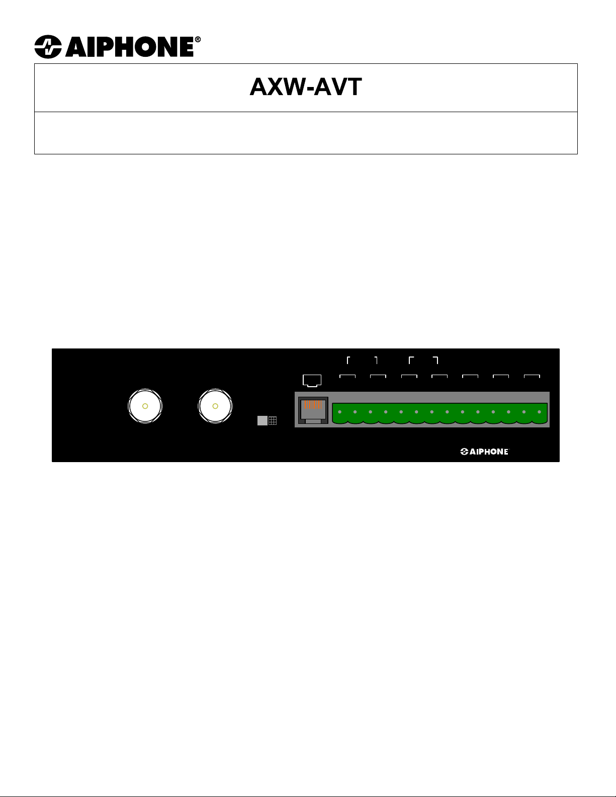
AXW-AVT
OUT IN
VIDEO
CCTV DOOR
DOOR
AUDIO
IN OUT
+ -
+ - + -
IN
+ -
CALL
+ -
SENSOR
NC NC
RELAY
NO NO
24VOUT
AXW-AVT
AXW-AVT TERMINAL DEFINITIONS:
DOOR (RJ-45 Jack): RJ-45 connection from AX-series audio video door, or spliced audio only door (IE/
IF-series).
AUDIO IN/OUT: Input / Output connections for audio transmission (line level, polarity indicated by
‘+’ and ‘-’).
CALL IN/OUT: Transistor-switched input / output to be connected to relay input / output on
transmission equipment. ‘Call In’ indicates call placed by door station, ‘Call Out’
indicates master-initiated activity (polarity indicated by ‘+’ and ‘-’).
SENSOR NC, NC: Normally Closed contact input, activates ‘Call In’ function when tripped by external
motion detector or other device with N/C contacts.
RELAY NO, NO: Normally Open relay contact, activated whenever communication is active.
VIDEO IN: Composite input signal from CCTV camera, if used in place of AX-series audio
video door station.
VIDEO OUT: Composite output to external transmission equipment. Source dependent upon
CCTV / DOOR switch.
CCTV / DOOR SWITCH: Determines whether AX-series audio/video door station video (‘DOOR’ setting) or
external CCTV video (‘CCTV’ setting) will be present on ‘VIDEO OUT’ for
connection to external transmission equipment.
24V +, - 24V DC input (use Aiphone PS-2420UL).
Pg. 1
Page 2
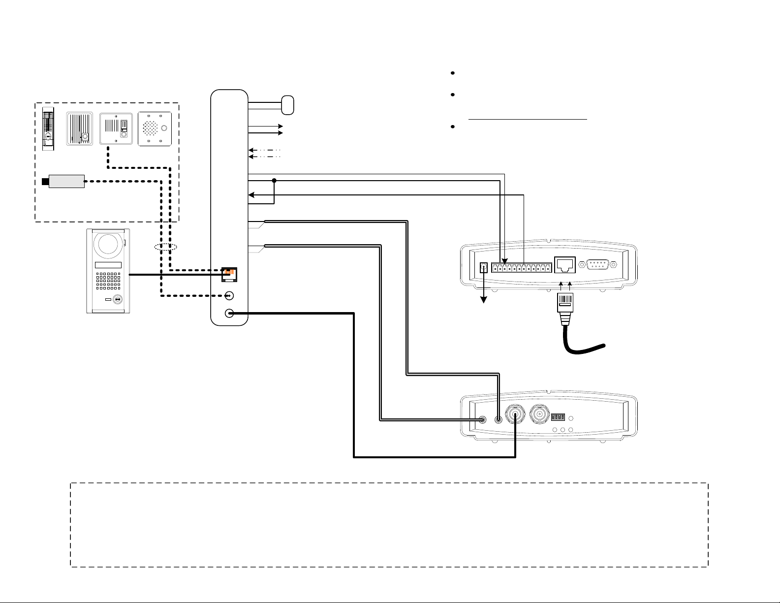
CONFIGURATION DIAGRAM:
AXW-AVT with Axis 243SA Video Server (Standalone Only)
AX-DM or IE/IF-Series
Audio Door Station
CCTV Camera
75 Ohm, 1V Peak-to-peak
(Independently powered)
*
AX-DV
Configuration Notes:
1. AX-series video door station connects to ‘DOOR’ input of AXW-AVT.
Ensure that the “CCTV / DOOR’ switch on the AXW-AVT is in the ‘DOOR’
position.
CAT-5e
Coax
AXW-AVT
24V
+
-
RELAY
NO
NO
SENSOR
NC
NC
CALL IN
+
-
CALL OUT
+
-
AUDIO IN
+
-
AUDIO OUT
+
-
DOOR
VIDEO IN
VIDEO OUT
PS-2420UL
+
-
Normally Open contact for remote device activation
(i.e. video switcher, DVR, etc.)
Normally Closed input for remote activation
(i.e. motion sensor, loop detector, etc.)
Coaxial Video Cable
Axis 243SA Application Considerations:
The Axis 243SA can only be used in ‘Standalone’ configuration (i.e.,
utilizing a PC as a master station).
When used in standalone configuration, Aiphone recommends
Controlware’s VIPDoorControl software. For further details, see
http://www.vipdoorcontrol.com.
Consult the Axis 243SA Installation and User manuals for further
information pertaining to video server installation and configuration.
POWER
1
23456789101112
To Axis-supplied
power source
NETWORK
RS-232
To Network
Axis 243SA
(Back View)
*2. Alternatively, an IE/IF-series or AX-DM audio door may be used, along
with 3rdparty CCTV camera. Connect audio door station to ‘Door’ input
(following the wiring method shown in the AX-series installation manual,
pg. 12). Connect the camera to ‘Video In’ and put the ‘CCTV / DOOR’
switch in the ‘CCTV’ position.
3. Connect the Call In / Call Out and Audio In / Audio Out connections on
LINE/MIC
IN
VIDEO
LINE
OUT
IN OUT
1 2 3 4
75Ω ON
STATUS
NETWORK POWER
AXIS 243SA
Video Server
Axis 243SA
(Front View)
the AXW-AVT to the Axis 243SA connectors, as shown.
4. Configure AXW-AVT internal jumpers as necessary (see Pg. 21).
Please Note:
Only information pertaining to the connection and operation of the AXW-AVT / AXW-AVR and listed 3
responsible for attempts to connect the AXW-AVT / AXW-AVR to untested 3
rd
party transmission hardware. Consult the installation manual for the 3rdparty device being utilized
for further information regarding physical mounting, base functionality, power requirements, etc. For the most up-to-date compatibility information, please consult http://
www.aiphone.com or contact Aiphone Technical Support.
For complete AX system installation, wiring, and programming information, please consult the AX Installation Manual (included on CD with AX Central Exchange Unit, or
Pg. 2 Pg. 3
available at http://www.aiphone.com).
rd
party devices interfacing with it are included here. Aiphone is not
Page 3

AXW-AVT Internal Jumper Settings:
The AXW-AVT has three internal jumper settings to control the functionality and conditioning of the audio
circuitry. These should be adjusted as necessary, based on the selection of fiber / Ethernet equipment used.
To access these jumpers, the chassis of the AXW-AVT will need to be opened. Adjusting these jumper
settings will NOT invalidate the AXW-AVT’s warranty.
Transmitting Gain (CN3): Controls the amount of amplification applied to the outgoing audio (‘Audio Out’)
connection of the AXW-AVT. A ‘Low’ setting provides no gain, whereas a ‘Hi’
setting applies approximately +10db of amplification. Default position is ‘Low.’
Receive Gain (CN4): Controls the amount of amplification applied to the incoming audio (‘Audio In’)
connection of the AXW-AVT. A ‘Low’ setting provides no gain, whereas a ‘Hi’
setting applies approximately +10db of amplification. Default position is ‘Low.’
Muting Circuit (CN5): The ‘Muting Circuit’ controls whether audio to/from the door station is
completely full-duplex, or limited to one direction or the other (semi-duplex).
This adjustment is required in situations where latency may be present between
audio transmission and reception (i.e., Ethernet). In such situations, the muting
circuit should be set to ‘On’ to reduce audible echoing. In situations where
latency is not an issue (i.e., fiber, direct connections, etc.), this should be left in
the default ‘Off’ position.
CN3: Transmitting Gain
High / Low
CN5: Muting Circuit
On / Off
CN4: Receive Gain
High / Low
Pg. 4
Page 4

SPECIFICATIONS:
Power:
AXW-AVT 24V DC, 500mA (use Aiphone PS-2420UL)
Video Input & Output: Composite 1V Peak-to-Peak, NTSC
Video Connectors: BNC
Door input: RJ-45
Relay: Normally Open contact output; 30V DC, 1A
Sensor: Normally Closed contact input
Wire: CAT-5e, 24AWG UTP-4
Wiring distance:
AXW-AVT to Door, Max. 980' cumulative
AXW-AVT to As close as possible; do not exceed 16'
3rdparty devices
Dimensions:
AXW-AVT 1-5/8"H x 7"W x 4"D
FCC Class B Verification
NOTE: This equipment has been tested and found to comply with the limits for a Class B digital device , pursuant to Part 15 of the FCC Rules.
These limits are designed to provide reasonable protection against harmful interference in a residential installation. This equipment generates,
uses, and can radiate radio frequency energy and, if not installed and used in accordance with the instructions, may cause harmful interference to
radio communications. However, there is no guarantee that interference will not occur in a particular installation. If this equipment does cause
harmful interference to radio or television reception, which can be determined by turning the equipment off and on, the user is encouraged to try
and correct the interference by one or more of the following measures:
— Reorient or locate the receiving antenna.
— Increase the separation between the equipment and receiver.
— Connect the equipment into an outlet on a circuit different from that to
which the receiver is connected.
— Consult the dealer or an experienced radio/TV technician for help.
Note:
Only information pertaining to the connection and operation of the AXW-AVT and devices interfacing with it are
included here. Aiphone is not responsible for attempts to connect the AXW-AVT to unte sted 3
hardware. For the most up-to-date compatibility information, please consult http://www.aiphone.com or contact Aiphone
Technical Support. For complete installation, wiring, and programming information regarding the AX system, please
refer to the AX Installation Manual, which is included on the CD provided with the AX CEU, or available for download at
http://www.aiphone.com.
rd
party transmission
Aiphone Communication Systems
1700 130th Ave. N.E.
Bellevue, WA 98005
(425) 455-0510
FAX (425) 455-0071
Toll Free Technical Support:
1-800-692-0200
E-mail tech@aiphone.com
Pg. 5
AXW-AVT Instr.
0309PHJD
 Loading...