

Page 1
AP-M High powered Intercom System
AP-10MS/C AP-20AS/C
AP-10AS/C AP-40AS/C
- INSTRUCTIONS -
The AP-MS/C system is a high powered, single talkpath open voice system. Multiple masters can be
used, along with a large variety of sub station models to create a communication system tailored to the
user's needs. The master station is available in an expandable 10-station size. For greater capacity,
include a 10-, 20- or 40-station add-on selector. Any "AS-" or "LS-" series sub station can be used. Any
10 watt 8 or 16 ohm speaker can be used for two way communication.(requires NP-25V).
NAMES & FEATURES
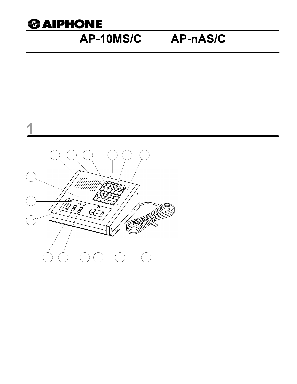
AP-10MS/C (pictured)
5
8764
9
NAMES & FUNCTIONS:
1. Power switch
2. Power indicator
3. Microphone
3
4. Speaker
5. OFF LED
6. OFF button
7. Terminal Block
2
8. Selector button
9. Station selector LED
10. AC power cord
1
11. Directory card
12. TALK button
13. Occupied LED
14. Transmit volume control
15. Receive volume control
15 10
14 13
12 11
FEATURES:
· High power output (10 Watt, 8 or 16 ohm).
· Single or multi-master capability.
· Commercial grade, durable master station for heavier usage.
· Single talkpath, with push-to-talk operation at master, and hands free communication
at sub station.
· Large variety of sub stations available:
- 8 ohm horn speaker with momentary call button (AH-108/NP-B).
- Surface or ceiling mount (AS-3A, AS-3N).
- Vandal proof and vandal proof weather resistant sub stations (LS-NVP/B, LE-SS, LE-SSR).
- Surface mount box for vandal proof stations (SBX-NVP).
- Any 8 or 16 ohm horn speaker can be used with a momentary call button (requires NP-25V)
· Selective calling to sub stations, and master-to-master communication.
· Subs call in with momentary tone and LED, remaining lit for approximately 20 seconds.
· Master is desk or wall mountable.
· 10-, 20- and 40-call add-on selectors available.
Pg. 1
Page 2
COMPONENTS & WIRING
Individual Components for System:
AP-10MS/C 10-call console-style master station
AP-10AS/C 10-call Add-on Selector
AP-20AS/C 20-call Add-on Selector
AP-40AS/C 40-call Add-on Selector
AS-3A Single call wall/desk mount sub station
AS-3N Ceiling mount sub station
LS-NVP/B Vandal proof sub station for AP-M system
SBX-NVP Surface mount box for LS-NVP
LE-SS 2-Gang, Stainless Steel sub station
LE-SSR 2-Gang, Stainless Steel sub with red mushroom call button
SBX-2G Surface mount box for LE-SS and LE-SSR
AH-108 8 ohm, 10 Watt horn speaker
NP-B Call in button
NP-25V Non-polarized, 25V , 33 mfd capacitor
SA-1 Surge Arrestor (1 per 2 wires being protected)
BA-1P Paging adaptor
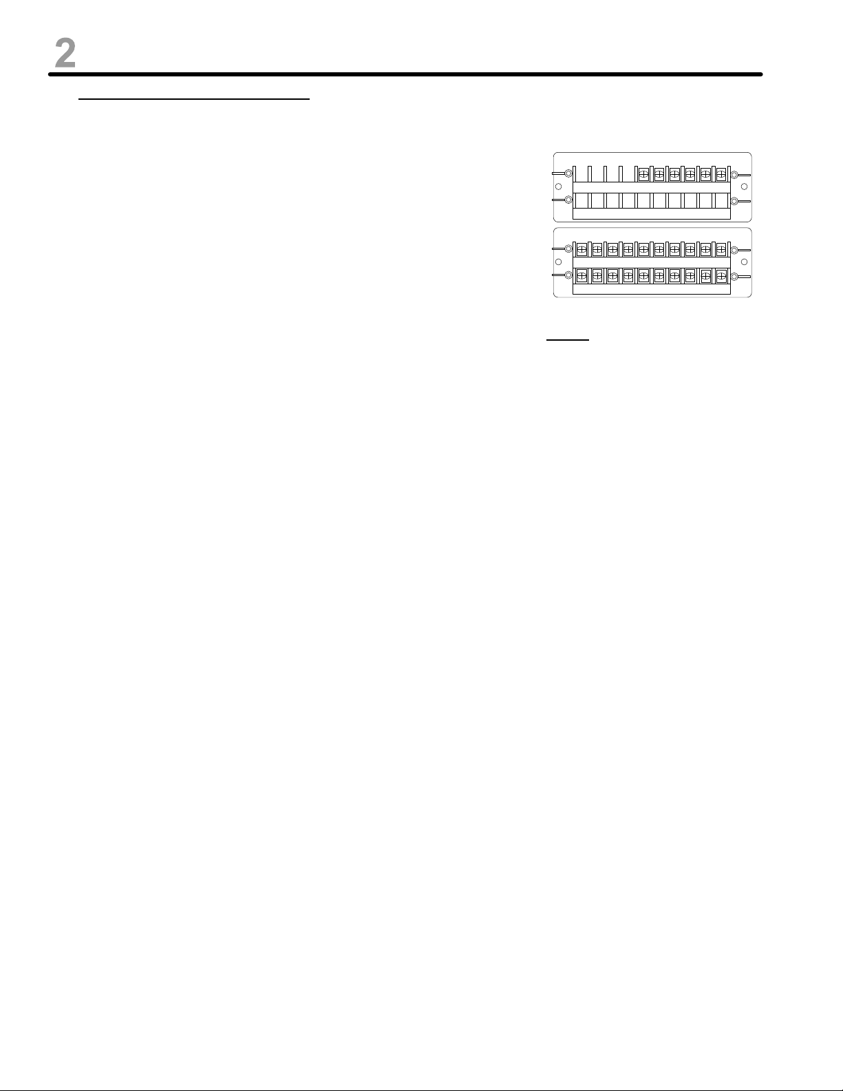
AP-10MS/C TERMINAL DEFINITIONS:
1~10 Station number, establishe s communication to other master or sub
C "CALL", for receiving a call from another master
E Common communication
GND Ground terminal
R Control for Occupied light
X1~X6 Connection for add-on selector
AP-10MS/C terminal block
X1X2X3X4X5X6
12345678910
GND
EEEEEEECR
NOTE:
Severe weather conditions, such as lightning
storms, may cause damage to AP-M/C
equipment. We recommend that power
surge protection be installed to minimize
potential component level damage. SA-1
surge arrestors should be installed on all
communication lines (one SA-1 for every two
wires connected to master.)
AP-20AS/C & AP-40AS/C TERMINAL DEFINITIONS:
1~40 Station number, establishe s communication to other master or sub
X1~X6 Connection for add-on selector:
X1 Red wire
X2 Black wire
X3 Blue wire
X4 White wire
X5 Brown wire
X6 Green wire
WIRING & INSTALLATION:
Before Installation:
· Make sure you have a proper power source and all necessary and compatible equipment for the system.
· Lay out your system in advance, assigning station numbers for all sub station locations.
· Surge protection for the intercom equipment is strongly recommended. Add SA-1 surge arrestors per two
wires connected to the master station.
Wire:
· Do not make any connections or attempt to install with power connected.
· Shielded wire is recommended. Use the proper gauge for the distance being run.
· Wiring between masters must be a multi-conductor cable. If more than one cable is used to connect
masters, the "E", "C", and number terminal wires must be in the same jacketed cable. If necessary, run
multiple "E" wires, one in each cable.
Wiring Method:
· Run intercom cables at least 20" away from all AC wiring, fluorescent lights, dimmer switches, and other
electrical or electronic devices. Wiring can cross AC wires at 90 degrees.
· Sub stations must be homerun to the nearest master station
Intercom Locations:
· Do not install intercoms near dimmer or light switches, or other electrical wall devices.
· To prevent feedback, do not place any stations back-to-back or on a common wall.
· Do not mount AP-M/C equipment in the following places, as it may cause the system to malfunction:
- High or extreme cold temperature areas: under direct sunlight, near equipment that varies in
temperature, in front of air conditioner, inside a refrigerated area, etc.
- Places subject to moisture or humidity extremes.
· AP-M/C units are electronic devices, whic h mus t not be subjected to water or any other liquid.
Pg. 2
Page 3

WIRING DIAGRAMS
3a. TWO MASTER STATIONS WITH SUBS WIRED TO DIFFERENT MASTERS
AS-3WA
1
2
E
AP-10MS/C AP-10MS/C
AS-3A
1
E
Master-to-master
communication
1
2
3
4
5
6
7
8
9
E
C
10
R
1
2
3
4
5
6
7
8
9
E
10
C
R
LS-NVP
Red
Blk
Grn
LE-SS
Red
AH-108
Blk
Grn
Retain
Black/Green
Jumper
3b. MASTER STATION WITH ADD-ON SELECTOR
AP-10MS/C
Red
Blk
Blu
Wht
Brn
Grn
1
2
3
~
10
E
C
R
X1
X2
X3
X4
X5
X6
Add-on Selector
AS-3A
1
E
AS-3N
Red
Red
NOTE:
AP-10AS/C &
AP-20AS/C wire
the same as
shown here.
AP-40AS/C
1
2
3
~
40
AS-3A
1
E
Wiring from
LS-NVP
Red
AH-108
Blk
Grn
Pg. 3
Page 4

OPERATIONS & SPECIFICATIONS
OPERATIONS:
* POWER SWITCH MUST BE ON FOR THE SYSTEM TO BE OPERATIONAL.
Receiving a call from a sub station:
1. Sub station calls in with mono-electronic tone, heard as long as call button at sub is depressed.
2. LED light corresponding to calling station will light at master, staying on approximately 20 seconds.
3. Depress station button with lit LED.
4. Press TALK button to speak, and release to listen.
5. Press OFF button to the left of the station selector button when the call is concluded.
Calling a sub or master station:
1. Depress station number of the location you wish to call.
2. Press TALK to speak, and release to hear reply.
3. If you wish to send a pre-announce tone to the called station, press the CALL button. A mono-electronic
tone will be heard at the called station.
4. Press OFF button to the left of the station selector button when the call is concluded.
Receiving a call from another master station:
1. When one master calls another master, no station LEDs light up, and the responding master answers
back hands free. The calling master uses the TALK button to speak.
2. The "occupied lamp" will be on while the initiating master has a station selected.
3. The responding master should not press any buttons to respond to another master's call.
SPECIFICATIONS:
Power Source: 110V AC
Power Consumption: 45W (Max.), 4W (Standby)
Communication Output: 300mW at 8 or 16 ohms (receive from subs and master to master)
10W at 8 or 16 ohms (transmit to subs)
Communication: Push-to-talk, release-to-listen (TALK button), hands free at sub station.
Calling: Master to sub or other master: By voice (TALK) or tone (CALL)
Sub to master: Call button on sub activates tone and LED at master,
remaining lit for approximately 20 seconds.
Wiring: One pair homerun from sub stations
(Single call subs to nearest master, dual call subs to both masters)
2 pair plus one pair for each station; master to master
Twisted, Shielded cable is recommended.
Wiring Distance: 510' with 22 AWG; 1,225' with 18AWG.
Dimensions: AP-10MS/C: 10" x 11" x 5-1/2". AP-10AS/C: 10-1/4" x 7" x 5-1/2".
AP-20AS/C: 10-1/4" x 7" x 5-1/2". AP-40AS/C: 10-1/4" x 12-7/8" x 5-1/2".
WARRANTY
Aiphone warrants its products to be free from defects of material and workmanship under normal use and
service for a period of one year after delivery to the ultimate user and will repair free of charge or replace at no charge,
should it become defective upon which examination shall disclose to be defective and under warranty. Aiphone
reserves unto itself the sole right to make the final decision whether there is a defect in materials and/or workmanship;
and whether or not the product is within the warranty.
This warranty shall not apply to any Aiphone product that has been subjected to misuse, neglect, accident, or
to use in violation of instructions furnished, nor extended to units which have been repaired or altered outside of the
factory. This warranty covers bench repairs only, and any repairs must be made at the shop or place designated in
writing by Aiphone.
Aiphone will not be responsible for any costs incurred involving on-site service calls.
Aiphone Communication Systems
1700 130th Ave. N.E.
Bellevue, WA 98005
(425) 455-0510
FAX (425) 455-0071
TOLL FREE TECHNICAL SUPPORT:
(800) 692-0200
E-MAIL: tech-serv@aiphone.com
AP-MS/C Instr.
Pg. 4
0105bkjs
 Loading...