

Page 1
® Al PHONE
INSTALLATION MANUAL
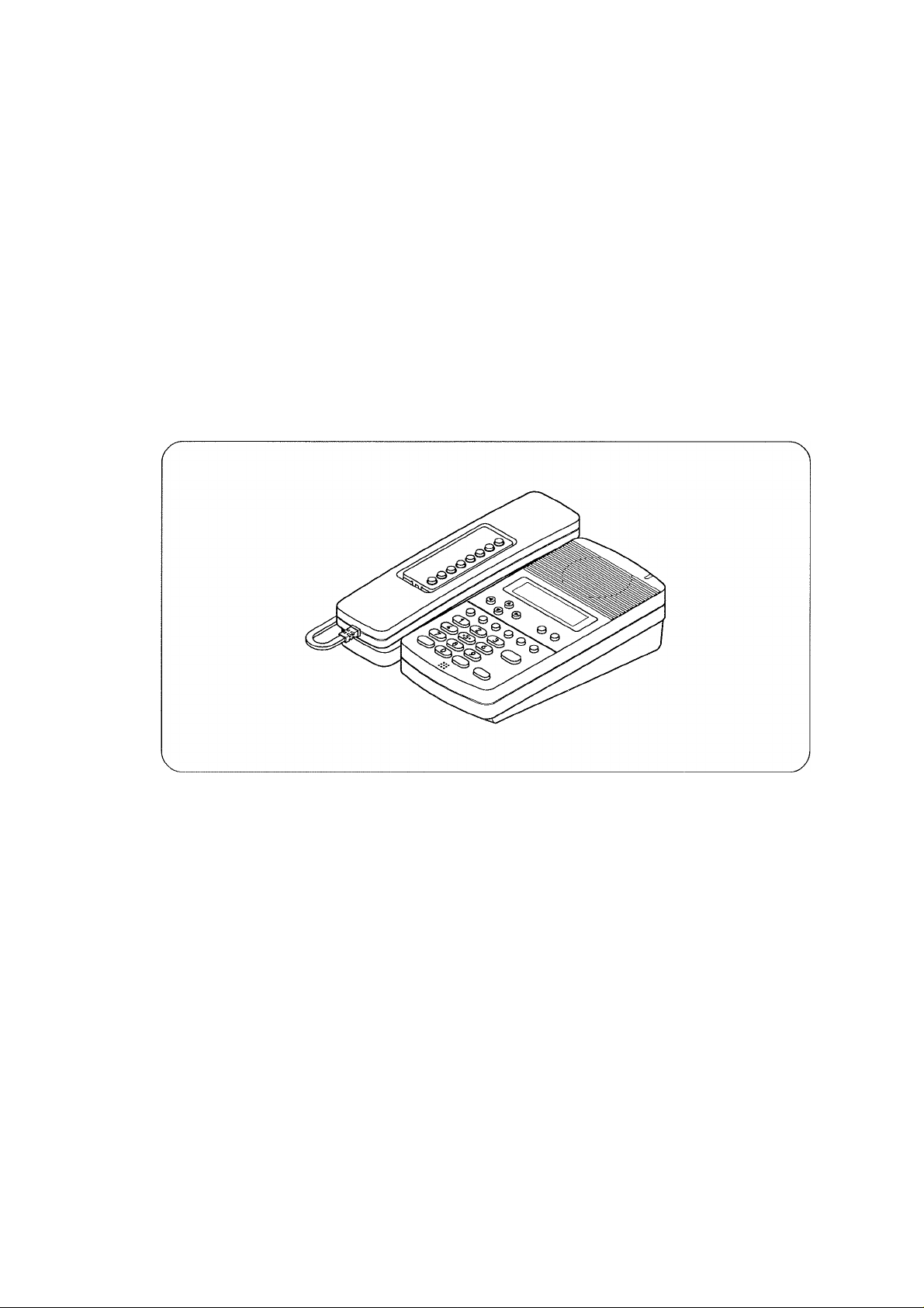
IP MULTIFUNCTIONAL MASTER STATION
AN-8500MS
Thank you for purchasing AlPHONE's IP Multifunctional Master Station.
Please carefully follow the instructions in this manual to ensure long, trouble-free use of your equipment.
1. SAFETY PRECAUTIONS
® Before installation or use, be sure to carefully read
all the instructions in this section for correct and
safe operation.
® Be sure to follow all the precautionary instructions
in this section, which contain important warnings
and/or cautions regarding safety.
® After reading, keep this manual handy for future
reference.
A CAUTION
Indicates a potentially hazardous situation which,
if mishandled, could result in moderate or minor
personal injury, and/or property damage.
When the Unit is in Use
® Use the dedicated AC adapter or its equivalent for
the unit. Note that the use of other adapter may
cause a fire.
Page 2
2. GENERAL DESCRIPTION
The AN-8500MS is an IP multifunctional master station designed for use with AlPHONE's network intercom system that
employs the packet audio technology*'.
Connecting the IP multifunctional master station to a network permits the ideal system for in-house or wide-area
information transmission applications, such as paging, periodical broadcasts, and background music broadcasts, to be
built in combination with the AN-8000MI Multi interface unit and AN-8000EX IP Intercom Exchange.
Using an optional YC-280 Wall mounting bracket, the station can be mounted on a wall, or tilted for easy key operation
when used on a desktop.
*' Technology related to audio transmission over a network.
3. FEATURES
• Clear conversations between stations over wide band.
• The system's echo cancellation*^ feature makes hands-free duplex conversation possible (conversations made without
using a handset at both parties) between stations.
• Can be connected to an existing local area network (LAN) or wide-area network (WAN). The system can also be easily
connected to fiber-optic networks without restrictions on operating distance.
• The dedicated software program enables centralized control with a personal computer.
• System maintenance (verifying operation log and line supervision) can also be performed with a personal computer and
Internet browser.
• Connecting the station to a PoE (Power over Ethernet) switching hub eliminates the need for an AC adapter.
• A PC can be cascaded with the station, if power is not supplied to the station, hub function will not work.
*2 A circuit that prevents acoustic feedback or echo generated when the voice output from the station's internal speaker
enters the microphone. ,
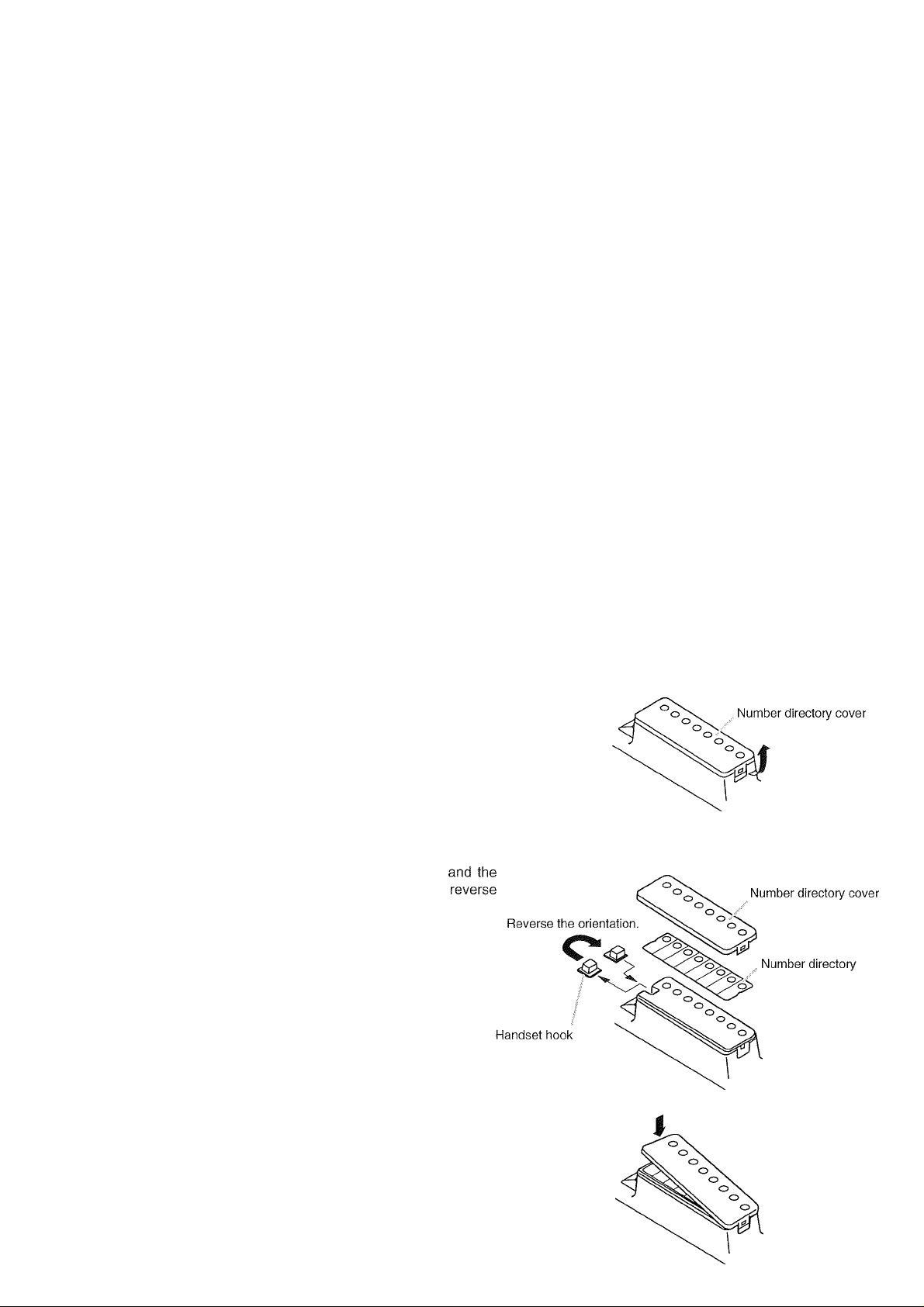
4. WHEN MOUNTING THE STATION ON A WALL
When mounting the station on a wall, the orientation of the handset hook needs to be changed.
Step 1. Raise the number directory cover forward tab.
its orientation, then replace.
Step 3. After replacing the directory on the station, hook
the directory cover's forward tab and push on the
upper part of the directory cover.
Page 3

5. WALL MOUNTING
The optional YC-280 Wall mounting bracket is required.
The YC-280 can be mounted to a one-gang electrical box.
5.1. Mounting
Step 1. Install the YC-280 to the wall.
Notes
• Use the appropriate screws for the construction
of wall.
• Wood screws 3.5 x 20 are supplied with the
YC-280.
• No fitting screws for an electrical box are
supplied.
Use commercially available screws.
Step 2. Hang the station on the wall mounting bracket
5.2. Installation Completion Drawing
hook to install.
Push down the station body in the direction
indicated by the arrows.
14R
YC-280
Unit: mm
YC-280
5.3. YC-280 Dimensional Drawing
4.6x6
Unit: mm
6. DESK-TOP INSTALLATION
In desktop installations, the front operation panel can be inclined 16° from the desk surface for easier operation by
attaching the YC-280 Wall mounting bracket to its bottom surface.
6.1. Mounting
Hang the YC-280's hook on the station's wall bracket mounting slot
to install.
Push up the YC-280 in the direction indicated by the arrows.
6.2. Installation Completion Drawing
Unit: mm
Page 4

7. WIRING
Power supply connection
The following 2 methods are available for
supplying power to the station.
• From a DC 12 V AC adapter
• From an IEEE802.3af compliant PoE
switching hub
(For connection, refer to the instruction
manual supplied with the switching hub
AC adapter connection
Connect the AC adapter*
Install the supplied ferrite /
clamp on the AC adapter /
cable by winding the f
cable around the ferrite »
clamp once.
Use the AC adapter AD-121 OP (optional) or the equivalent.
As for the usable adapter, consult the AlPHONE sales
office.
AN-8500MS rear
□
c
_______
______
■
J
i
External speaker connection
Press down the desired push
in terminal button with a tip of
standard driver, and insert
the cable securely.
' Applicable cables are as follows.
Conductor diameter:
00.4- 1.3 mm (AWG16-26), Solid wire
00.7- 1.4 mm (AWG16-22), Stranded wire
' When using the external speaker,
set the internal/external speaker
switch on the bottom to the EXT.
SP position.
8. ACCESSORY
CD*
..............
Ferrite clamp
Contains the AN-8000 setting software program and
the AN-8000 series instruction manual. The Setup
Launcher is automatically started when the supplied
CD-ROM is inserted into the PC's drive.
Note
If your PC's CD drive is not compatible with the
AutoRun function, the setup guide is not automatically
started even when the CD is inserted. Use either
"Explorer" or "My Computer" to execute the following
files, or use [Start -♦ Run] in the Task Bar and enter
the following command.
<Drive where CD is placed> \index.html
For example, when placing the CD in the "d" drive,
-*■ d:\index.html
Use a UTP category 5 straightthrough cable with an RJ-45
connector for this connection.
To network
Can be connected to a network of 10BASET/100BASE-TX in auto-sensing.
Use a UTP category 5 straight-through cable
with an RJ-45 connector for this connection.
8. OPTIONAL PRODUCTS
AC adapter: AD-1210P
Wall mounting bracket: YC-280
-----------------Version update information
Please contact to the AlPHONE sales office to obtain
the up-to-date version for firmware, software and the
instruction manuals.
The software version number can be confirmed using
the Help menu.
The current firmware version can be confirmed on the
system management screen displayed when the
browser establishes the connection to the station.
The instruction manual version number can be
confirmed by checking the preparation date (year and
month) shown at the lower right corner of the last
page.
Example: Prepared in July 2006: 200607
------------------
 Loading...