

Page 1
® AlPHONE
INSTALLATION MANUAL
FLUSH-MOUNT MASTER STATION
Thank you for purchasing AlPHONE's Flush-Mount Master Station.
Please carefully follow the instructions in this manual to ensure long, trouble-free use of your equipment.
1. GENERAL DESCRIPTION
The AN-8031 MS is a flush- or surface-mount master
station designed to operate in conjunction with AlPHONE
IP Intercom Exchange and features high quality hands-free
conversation.
Connecting a foot switch or other external switch to the
external dial input terminal permits one-touch dialing
operation by way of such switches.
Handset conversation can be made in conjunction with the
optional RS-191.
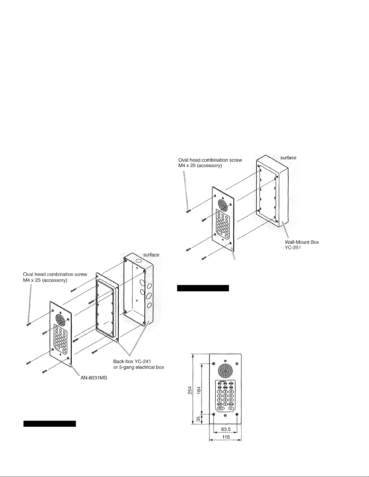
2. WALL MOUNTING
2.1. In-Wall Mounting Using an eiectricai box
2.2. On-Wall Mounting Using a Wall-Mount box
Attach the AN-8031 MS to the YC-251 Wall-Mount Box
installed on a wall.
AN-8031 MS
Wall
Attach the AN-8031 MS to the YC-241 Back Box or an
electrical box installed in a wall.
Wall
Note
The wall should be over 12 mm thick, and the opening in
the wall for an electrical box should be under 115 mm
(wide) by 254 mm (high).
AN-8031 MS
Accessory screws
The AN-8031 MS comes with 2 types of screws: oval head
combination screw M4 x 25 and oval head slotted screw
UNC No.6 X 18.
For the electrical box provided with unified threads, use the
oval head slotted screws UNC No.6 x 18.
[Installation completion drawing]
Unit: mm
Accessory screws
The AN-8031 MS comes with 2 types of screws: oval head
combination screw M4 x 25 and oval head slotted screw
UNC No.6x 18.
For the electrical box provided with unified threads, use the
oval head slotted screws UNC No.6 x 18.
Page 2
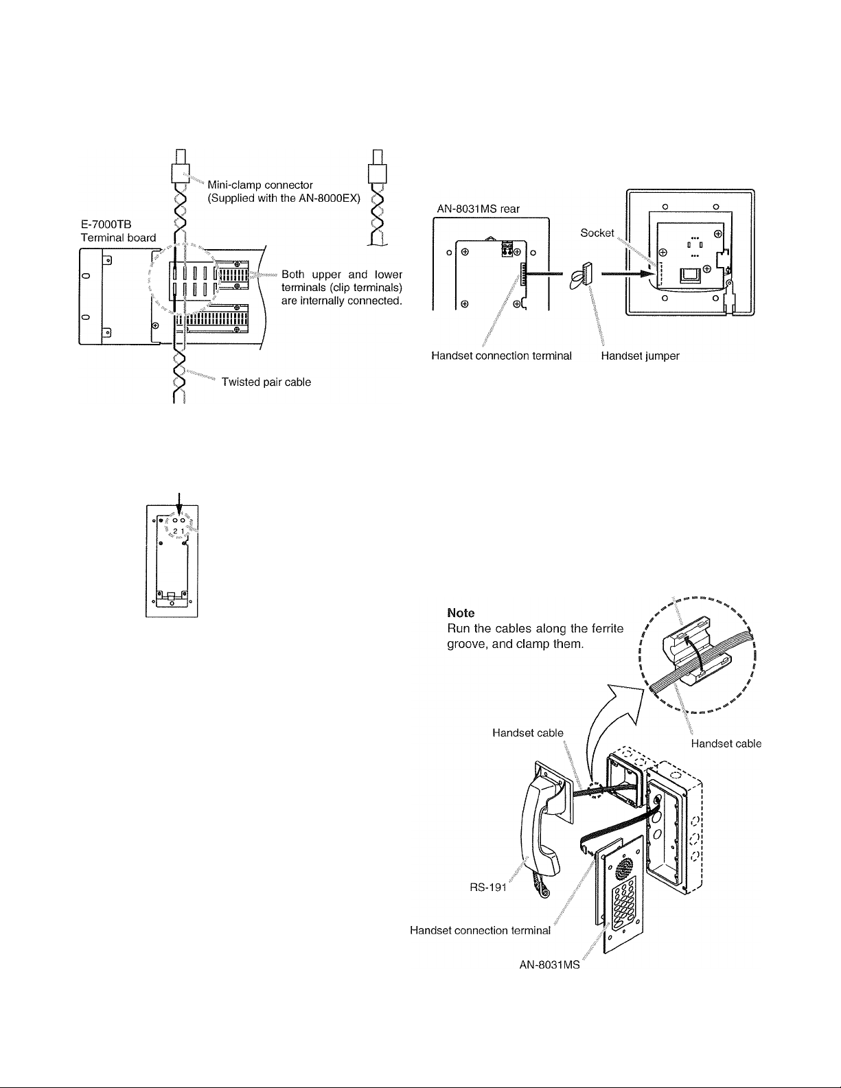
3. WIRING
3.2. Connection to RS-191
3.1. Connection to the Exchange
AN-8000EX Exchange
16 lines
©a
M
Removable terminal plug (2P)
(accessory)
Line connection terminals
Connecting the RS-191 Option Handset to the AN-8031 MS
permits handset conversation.
Step 1. Remove the handset jumper attached to the AN-
8031MS's handset connection terminal, then
insert it to the socket on the RS-19Ts rear PC
board.
RS-191 rear
Note
Though the socket on the PC board is faced inside, you
can insert the handset jumper into the socket from the
side.
Step 2. Install the ferrite clamp (supplied with the AN-
8031 MS) onto the RS-191's handset cables.
Then, connect the cables to the AN-8031 MS's
handset connection terminal.
Ferrite clamp (accessory)
AN-8031 MS rear
To connect the cables from the AN-8000EX Exchange to
the AN-8031I\/IS, use the removable terminal plug (2P)
supplied with the AN-8031MS.
The cables have no polarity.
Page 3

3.3. Connection to External Switch 3.4. The Type of Cables
External switches such as footswitches can be connected
to the AN-8031 MS's external dial input terminals.
Terning on each switch connected to the terminal [7], [8],
[9], or [C] permits the same operation as performed by
pressing the dial [7], [8], [9], or [C],
Note
The cable length from the external switch should not
exceed 3 m.
[Connections]
The types of cables are to be determined according to the
following conditions.
• Twisted pair wires (such as those used for electronic
push-button telephone) are to be used for wiring between
the Exchange and the stations in principle.
® The number of cables pairs laid should be determined
considering the possibility of future expansion of the
system.
® Outdoor wires should be used where wiring passes
through inaccessible areas such as ceilings or under
floors where the maintenance is not performed. Indoor
wires may also be used, however, in case where there is
no risk of deterioration due to exposure to heat, etc.
Note
Specifications related to each junction are as follows.
Mini-clamp connector (AN-8000EX line terminal)
Conductor diameter: 0 0.4 - 0.65 mm (AWG22 - 26),
Solid wire
Outside diameter: 0 1.05 mm or below
Clip terminal (E-7000TB)
Conductor diameter: 0 0.4 - 0.8 mm (AWG20 - 26),
Solid wire
Outside diameter: 0 1.5 mm or below
Removable terminal plug (AN-8031 MS line terminal)
Conductor diameter: 0 0.4 - 1.6 mm (AWG14 - 26),
Solid wire/Stranded wire
External dial input terminal (AN-8031 MS)
Conductor diameter: 0 0.8 - 1.3 mm (AWG16 - 20),
Solid wire/Stranded wire
3.5. Relations Between Core Diameter of Cable
and Maximum Cable Length
Refer to the following chart as guidelines when designing
the distance between the Exchange and stations so that
loop resistance value becomes 170 O or less.
Conductor
diameter
(mm)
0O.4
0O.5 187
00.65 113
0O.9 58
Loop Maximum cable length
resistance between the Exchange and station.
(0/km)
295
(Assuming that the loop resistance is 170 Q)
570 m
900 m
1.5 km
2.9 km
Page 4

3.6. Terminal Station Connection 3.7. Terminal Plug Connection
Mini-clamp connectors for line terminals and removable
terminal plugs for paging output terminal are supplied with
the AN-8000EX Exchange.
Perform each connector connection as follows.
Step 1. Cut off two-cable ends in equal length, and insert
them securely to a cover section (transparent
side) of the mini-clamp connector.
Note
Insert the cable without stripping the cable jacket.
Cover
(transparent side)
Cable
Step 2. With a pair of pliers, lightly pinch the mini-clamp
cover and, after ensuring that the cable is
securely inserted, firmly squeeze on the cover.
Note
Squeeze on the mini-clamp cover until it is
correctly locked.
Step 1. Strip a cable jacket of approx. 5 mm from the
cable end.
5 mm
Note
Do not solder plate on exposed inner cables
when using a stranded wire.
Step 2. Loosen the terminal screws and insert the cables.
Step 3. Tighten the terminal screws securely.
Notes
® Tug lightly on the cable to be sure that it does
not pull free. If the cable pulls free, loosen the
terminal screw again and reconnect from Step 2.
» To avoid stripping the screws, use the
screwdriver appropriate to the screws tightened
into the terminal plug.
Step 4. Insert the wired terminal plug into the pin header
on the AN-8031 MS's PC board.
steps. Insert the wired connector (plug) into the
exchange's connector (socket) until it locks into
place.
Cable
D4 ? (accessory)
Removable terminal plug
\
®AIPHONE'
no Pe>n r
 Loading...