

Page 1
AC-10S, AC-10F
Access Control
Clavier à Codes rétro-éclairé
Türcodemodul
Control de acceso
Codeklavier
FK1376
A
YS0108
Surface mount type
Clavier saillie
Aufputztyp
Montaje en superficie
Opbouwmontage
AC-10S AC-10F
Flush mount type
Clavier encastré
Unterputztyp
Montaje empotrado
Inbouwmontage
INSTALLATION & OPERATION MANUAL
NOTICE D'INSTALLATION ET D'UTILISATION
INSTALLATIONS- UND BEDIENUNGSANLEITUNG
MANUAL DE INSTALACIÓN Y USO
INSTALLATIE & GEBRUIKSHANDLEIDING
Page 2
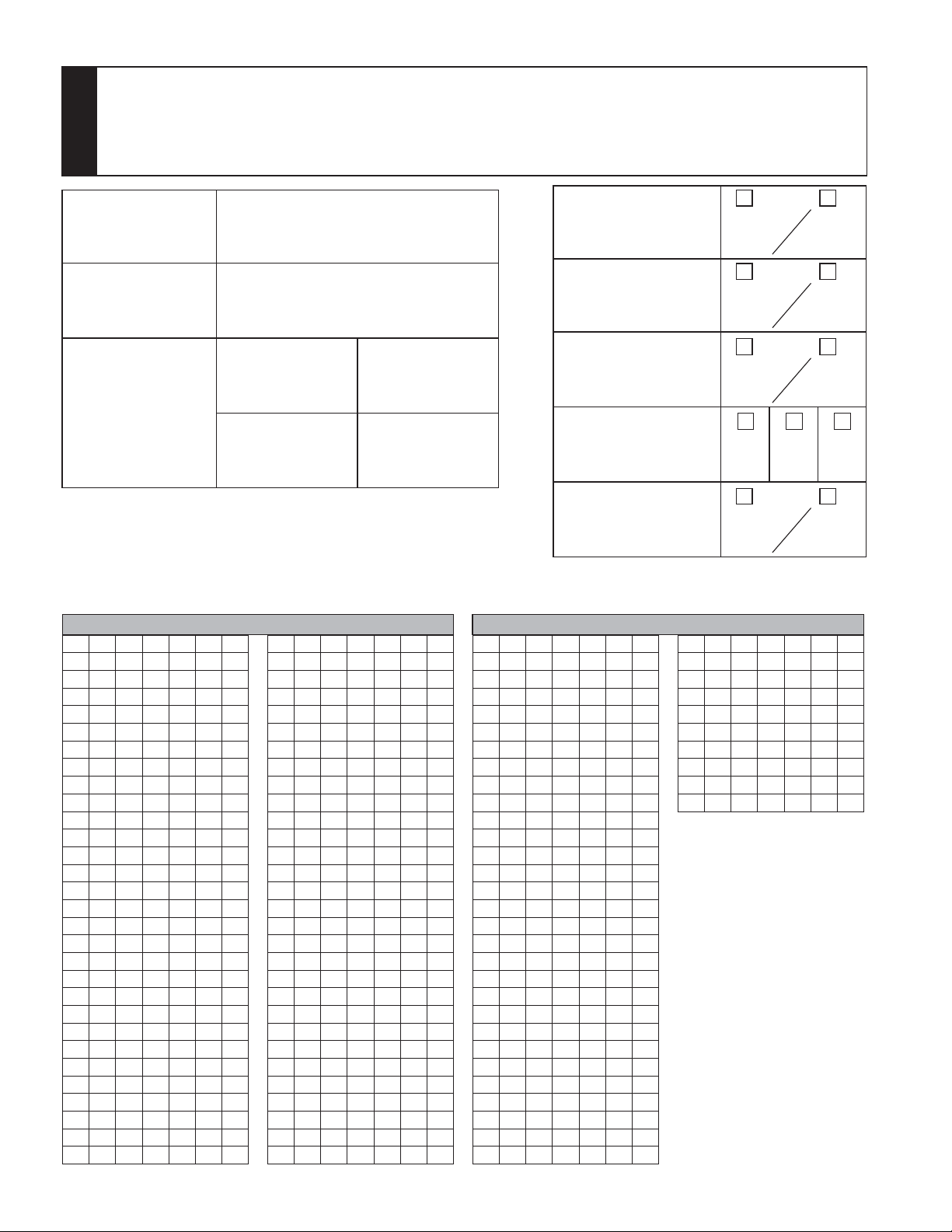
RECORD OF SETTINGS AND REGISTRATION DETAILS (Please make sure to write down your settings below.)
AIDE MEMOIRE DES PROGRAMMATIONS ENREGISTREES (Faire en sorte de bien noter vos réglages ci-dessous.)
VERZEICHNIS DER EINSTELLUNGEN UND REGISTRIERUNGSDETAILS (Bitte notieren Sie unten Ihre Einstellungen.)
DATOS DE CONFIGURACIÓN Y DETALLES DE LOS REGISTROS (Asegúrese de apuntar los valores de ajuste abajo.)
LIJST MET GEPROGRAMMEERDE INSTELLINGEN EN CODES (Zorg ervoor uw instellingen hieronder op te
schrijven.)
Master code
Code maître
Mastercode
Código maestro
Hoofdcode
Key illumination time
Temporisation d'éclairage
Tastenbeleuchtungszeit
Tiempo de encendido de las teclas
Verlichtingsduur klavier
Relay output time
Temporisation des relais
Relais Ausgabezeit
Tiempo de salida Relé
Relais outputtijd
Relay 1
Relais 1
Relais 1
Relé 1
Relais 1
Relay 2
Relais 2
Relais 2
Relé 2
Relais 2
sec/sek/seg
sec/sek/seg
sec/sek/seg
External output setting
Paramétrage de sortie externe
Externer Ausgang
Ajuste de la salida externa
Activering Alarmuitgang
ON
EIN
AAN
Lockout
Blocage
Eingabe-Sperre
Bloqueo
Blokkering klavier
ON
EIN
AAN
Auto-relock
Auto-reverrouillage
Automatische Neuverriegelung
Re-bloqueo automático
Automatische hersluiting
ON
EIN
AAN
Timer-linked unlocking
Déverrouillage lié à l'horloge
Timergesteuerte Entriegelung
Desbloqueo conectado al temporizador
1 2 1&2
Tijdsgebonden ontgrendeling
Operation tone
Bip de fonctionnement
Signaltöne
Tono de operación
Zoemer klavier
ON
EIN
AAN
Registered User Code List / Liste des codes utilisateur programmés / Liste der registrierten Zugangscodes
Lista de códigos de los usuarios registrados / Lijst Codes Geregistreerde Gebruikers
group 1 / groupe 1 / gruppe 1 / grupo 1 / groep 1 group 2 / groupe 2 / gruppe 2 / grupo 2 / groep 2
00
01
02
03
04
05
06
07
08
09
10
11
12
13
14
15
16
17
18
19
20
21
22
23
24
25
26
27
28
29
30
31
32
33
34
35
36
37
38
39
40
41
42
43
44
45
46
47
48
49
50
51
52
53
54
55
56
57
58
59
60
61
62
63
64
65
66
67
68
69
70
71
72
73
74
75
76
77
78
79
80
81
82
83
84
85
86
87
88
89
90
91
92
93
94
95
96
97
98
99
OFF
AUS
UIT
OFF
AUS
UIT
OFF
AUS
UIT
OFF
AUS
UIT
1
Page 3
English
PRECAUTIONS
General Prohibitions Prohibition to Dismantle the Unit
General Precautions
WARNING
(Negligence could result in death or serious injury to
people)
1. Do not connect any non-specified power source to the
V, V terminals, and do not install two power supplies in
parallel to a single input. Fire, damage to the unit, or
system malfunction could result.
2. The unit is not explosion-proof. Do not install or use
near gases or flammable materials. Fire or explosion
could result.
3. Do not dismantle or alter the unit. Fire or electric shock
could result.
4. Do not allow the wires or DC output terminals to be
shorted. Fire or electric shock could result.
CAUTION
(Negligence could result in injury to people or damage
to property)
1. When mounting the unit on a wall, install the unit in a
convenient location, but not where it could be jarred or
bumped. Injury could result.
2. Do not install or make any wire terminations while
power supply is plugged in. It can cause electrical
shock or damage to the unit.
3. Before turning on power, make sure wires are not
crossed or shorted. Fire or electric shock could result.
4. Do not install the unit in any of the following locations.
Fire, electric shock, or unit trouble could result.
* Places subject to dust, oil, chemicals, hydrogen sulfide
(hot spring).
* Places subject to moisture and humidity extremes,
such as bathroom, cellar, greenhouse, etc.
* Places where the temperature is quite low, such as
inside a refrigerated area or in front of air-conditioner.
* Places subject to steam or smoke (near heating or
cooking surfaces).
* Where noise generating devices such as dimmer
switches, invertor electrical appliances, are closeby.
GENERAL PRECAUTIONS
1. This product, being a control unit of door release,
should not be used as a crime-prevention device.
2. This product is weather-resistant, but do not spray
high-pressure water on it. Unit trouble could result.
3. The product becomes inoperative during power failure.
4. As to other manufacturer's devices, such as sensor,
door releases, timer, used with this system, comply
with the Specifications and Warranty conditions
manufacturers or venders present.
English
Français Deutsch Español
Nederlands
CONTENTS
RECORD OF SETTINGS AND REGISTRATION DETAILS
PRECAUTIONS …………………………………………… 2
PACKAGE CONTENTS …………………………………… 2
NAMES ……………………………………………………… 3
MOUNTING ………………………………………………… 3
MOUNTING/WIRING METHOD, WIRING DISTANCE
…1
…… 4
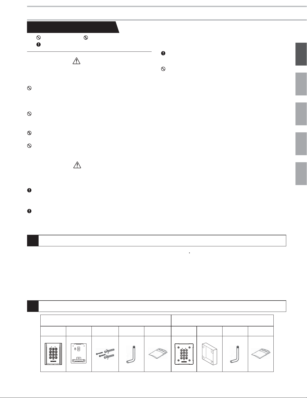
PACKAGE CONTENTS
AC-10S AC-10F
Unit
Mounting
bracket
Mounting
screws
Special
screwdriver
FUNCTIONS
OPERATIONS ……………………………………………… 9
TECHNICAL PRECAUTIONS …………………………… 9
SPECIFICATIONS ………………………………………… 9
WARRANTY ………………………………………………… 9
TEMPLATE FOR AC-10S MOUNTING BRACKET (SCALE 1:1)
Operation
manual
SETTING UP ……………………………… 5
Unit
Flush mount
back box
Special
screwdriver
…42
Operation
manual
2
Page 4
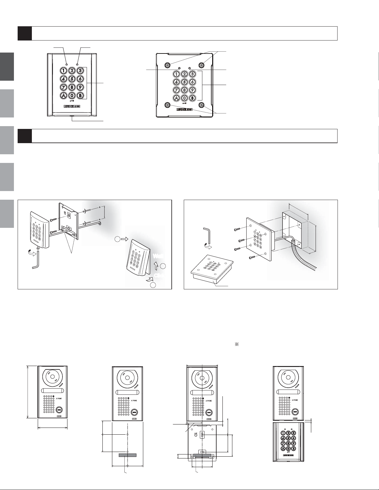
NAMES
98mm (3-7/8")
11.5mm (7/16")
3.5mm
(1/8")
49mm (1-15/16")
42.5mm
(1-2/3")
55mm
(2-3/16")
68.5mm (2-11/16")
「Cable inlet」
64mm (2-1/2")
15mm (9/16")
t
12
English
3
FrançaisDeutschEspañol
4
MOUNTING
AC-10S
1.
Drill holes in the wall to match the size and number of screws.
2. Attach the mounting bracket to the wall using the
mounting screws.
3.
Attach the unit to the mounting bracket using the special
screwdriver and the special screw for mounting.
AC-10S
55mm (2-3/16")
Nederlands
4
1 LED indicator (Orange)
1
2
3
4
2 LED indicator (Green)
3 Keys (Yellow)
4 Special screws for panel mounting
AC-10F
1.
Detach the AC-10F panel using the special screwdriver
supplied.
2. Attach the flush mount back box to the wall.
3.
Attach the panel to the flush mount back box using the special
screwdriver and the special screws for panel mounting.
AC-10F
85mm (3-3/8")
Cable
Spare screw holes
1
WallWall
3
Click
2
Flush mount back box
When this unit is to be used with the JF-DV, please refer to the illustration below when installing it.
Please also refer to "TEMPLATE FOR AC-10S MOUNTING BRACKET(SCALE 1:1)"(page 42).
1. JF-DV unit
173mm (6-13/16")
2.
Positions for drilling holes
Please refer to the
illustration below when
drilling the holes. Make
sure the cable inlet is within
the shaded area shown in
the illustration below.
3. Position of mounting bracket
Refer to the illustration
below when attaching the
mounting bracket.
Attach the unit to the mounting bracket
by pushing it into the bracket. Tighten
the screws to complete the installation.
( )
As there are drain holes at the bottom
of the JF-DV unit, do not block the space
between the JF-DV and the access control
keypad.
100mm
(3-15/16")
45mm
(1-12/16")
4. Installation
3
98mm (3-7/8")
42.5mm
(1-2/3")
55mm
(2-3/16")
49mm
(1-15/16")
49mm
(1-15/16")
A hole for cable inle
5mm
(※)
(3/16")
Page 5
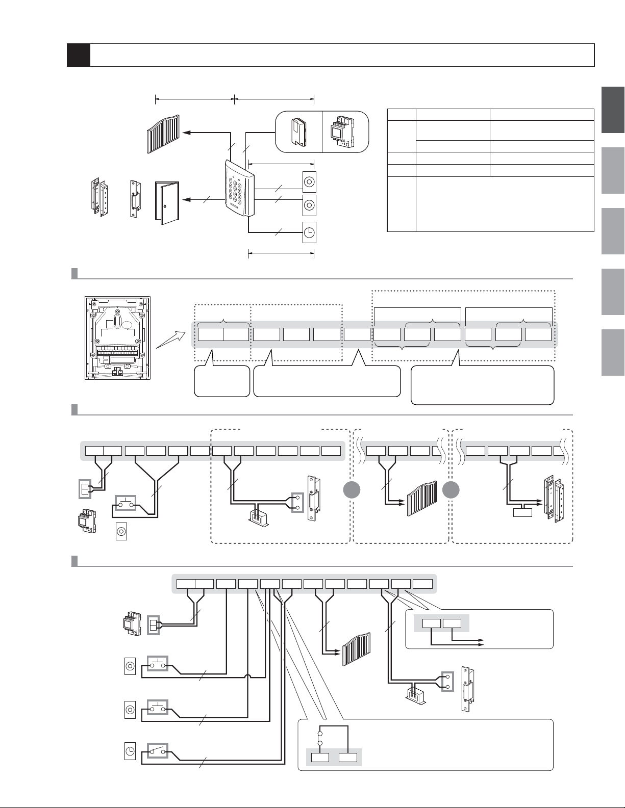
MOUNTING/WIRING METHOD, WIRING DISTANCE
Automatic gate
or
Electromagnetic
door lock
rminal names
Te
Back view of AC-10S
Electric
door strike
Connection of Relay 1 only
Relay
2
Relay
2
Power supply
Power supply
Between 12 and 24V AC
Between 12 and 24V DC
AD
Power supply
2
B
2
2
2
C
Request to
VV
Exampleofelectricdoor
strikeconnection(N/O)
Request to
exit/entry
exit/entry
button 1
button 2
PB2PB1
Request to exit/entry button ・Timer
Minimum overload :100mV DC, 0.1mA or above
・
・Contact capacity: 3V DC, 0.1A or above
Request to exit/entry
button
Request to exit/entry
button
Timer
Common Timer
TC
(Wiring distance)
Power supply
AC/DC12 ~ 18V
A
AC/DC18 ~ 24V
B
C
The connection distance will depend on
the specifications of the electric door strike,
relays or Electromagnetic door lock to be
D
connected. To determine the operating range,
please refer to the specifications of each
terminal.
User group1 relay 1 User group2 relay 2
N/C contact
NO1
Exampleofautomatic
gateconnection(N/O)
C1
N/O contact N/O contact
Relay
24V DC, 3A (resistive load) 1A (inductive load)
24V AC, 3A (resistive load) 1A (inductive load)
・Minimum overload :5V DC, 100mA or above
(Less than)
-
- 300m (980')
NC1
Exampleofelectromagneticdoor
diameter 0.65 - 1.0 mm (22-18AWG)
100m (330')
300m (980')
300m (980')
N/C contact
C2
NO2
lockconnection(N/C)
NC2
English
Français Deutsch Español
Nederlands
C2
NC2
2
Power supply
VV
NP
Request to exit/entry button
(push button, etc.)
TC
NO1
C1
NC1PB2PB1
NO2
Electric door strike
2
2
NP
NP
AC transformer
Relay 1: Automatic gate (N/O contact), Relay 2: Electric door strike (N/O contact)
TC
NO1
N.C
2
PB2
C1
NP
Power supply
Rating
Between 12 and 24V AC
Between 12 and 24V DC
For relay 1
Request to
exit/entry button
For relay 2
Request to
exit/entry button
Timer
VV
2
NP
2
NP
2
NP
2
NP
NO1
2
NC1 NO2
2
Automatic gate
Auto-relock/External out put by forced entry
(sensor connection is required)
・To setVJG
sensor (locally avallable) is required.
C
・The request to exit/entry button for relay 2 cannot be used when the
"auto-relock" / "External out put by forced entry" function are set.
NC1
C1
NP
Automatic gate
C2
NC2PB2PB1
NP
NO2
AC transformer
"
auto-relock" / "External output by forced entry" function a
NO1
oror
C2
Electric door strike
C1
NC1 NO2N
Electromagnetic
2
door lock
NP
PS
Power supply
External output
Only connecting to the terminal
of relay 2 is possible.
Alarm, Security
C2
4
Page 6
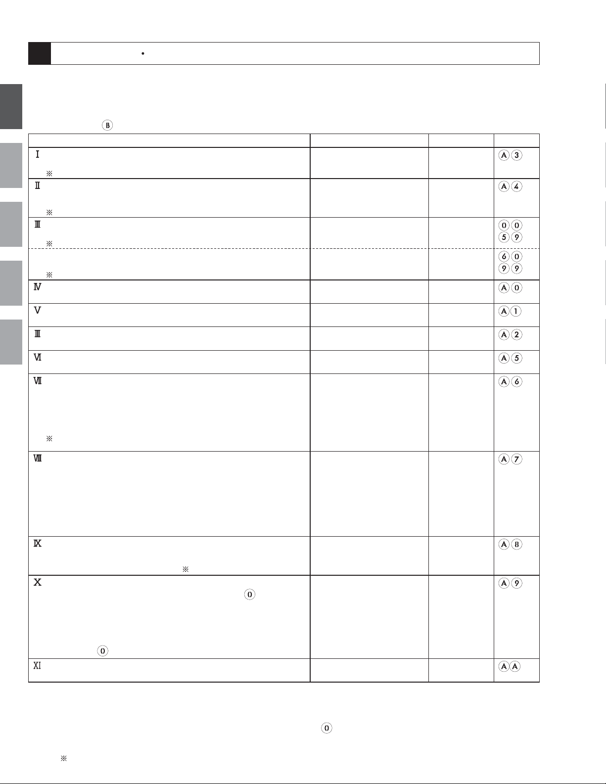
FUNCTIONS SETTING UP
This section explains the settings of each function, including the master code for management, the user code for unlocking, the
buzzer and the LEDs.
About the setting mode:
Enter master code twice to switch to the setting mode, and enter the following setting code to perform the settings
for the desired function. After settings have been made, enter the following setting codes to continue the setting
English
operation. Press
Setting the code length
Change the length of the master code and the user code.
FrançaisDeutschEspañol
)They both must be the same length.
Setting the master code
Enter a master code using between 4 and 6 digits (alpha or numeric) to
switch to the setting mode.
) The number of digits in the code can be set by setting the code length.
Setting the code for user group 1
Set the unlocking code for user group 1.
) The number of digits in the code can be set by setting the code length.
Setting the code for user group 2
Set the unlocking code for user group 2.
) The number of digits in the code can be set by setting the code length.
Setting the key illumination time
Set the length of time that the keys will be lit up after they are pressed.
Setting the relay 1 output time
Set the output time of relay 1.
Setting the relay 2 output time
Set the output time of relay 2.
Reset Settings
Nederlands
Return all the settings to their default values.
External output setting
The alarm or security system connected to the terminal of relay 2 will be
activated when the "Lockout" * or the forced entry* is carried out.
* "Lockout": Refer to VIII below. *Forced entry: This function is linked with
the door open/close sensor (N.C.) which is connected to PB2 and C, and
carried out when opening the door without activating this unit. (For example,
entry in an improper manner, manual unlock, etc.)
) If there is a way to open the door without activating this unit, such as
manual unlock, do not make the external output setting for the forced entry.
Lockout
If several incorrect access codes are attempted, the code input function is
disabled for a programmed period of time.
· When "Lockout" is activated, the LED (Orange) indicator and the keypad
blink, and the buzzer sounds for 3 seconds. This is just a sound to inform
you that the function has been activated. It is not a warning sound. If you
want a warning to be sounded, please use the external output function to
activate a commercially-available alarm device.
· The unlock function will work when the request to exit/entry button is
pushed, even while the "Lockout" function is operating.
Auto-relock (Anti-tailgate)
After the door has been linked to the door open/close sensor (N/C), and
unlocked, it will relock itself one second after being closed, thus preventing
the entry of an unauthorized third party.
Timer-linked unlocking setting
The system can be set to unlock the door by pressing the key within
the set time and linking it to the external timer (N/O). The operations for the
LEDs and the buzzer after unlocking are the same as those used to perform
user code unlocking. When the door is linked to the timer, unlocking can be
performed using the user code and the request to exit/entry button. When
latch output is performed for the relay settings, the relay turns ON/OFF
every time the
Operation tone settings
Set the tone heard when the keypad is being used to ON/OFF.
• The setting can be saved even when the power is off.
• The system cannot be switched to the setting mode while the relay is unlocked.
• When the setting mode has been activated and no operations are performed for approximately 120 seconds, the system
will exit the setting mode. (If a key is pressed during that time, the timer will start over.)
• Neither the request to exit/entry button nor the timer-linked unlocking
user code cannot be performed while the setting mode is activated.
• The volume (the check tone, operation tone, etc.) from the main unit may become lower according to the mounting status.
1
5
: When the auto-relock is used, the request to exit/entry button for relay 2 cannot be used. The output of relay 2 is
only possible when user code unlocking is performed.
to exit the setting mode.
Setting items Allowable setting range Default value
)1
key is pressed.
Setting code
4, 5, or 6 digits 4 digits
1
1234
Valid keys: 0 - 9, A, B
Number of codes: 60
-
Valid keys: 0 - 9, A, B
Number of codes: 40
-
Valid keys: 0 - 9, A, B
Illumination time: 10 to 99
10 Sec.
seconds, or continually lit
Output time: 1 to 99
3 Sec.
seconds, or latched
Output time: 1 to 99
3 Sec.
seconds, or latched
--
· OFF
OFF
· During Lockout
· During forced entry output
·
During lockout and forced
entry output
ON/OFF
OFF
Invalid number of times:
10 to 99 times
Invalid time:
10 to 99 seconds
ON/OFF OFF
Linked relay: relay 1
Linked relay: relay 1
relay 2
relay 1 and 2
0 key illumination: OFF
0 key illumination: ON/OFF
ON/OFF ON
key can be operated, and unlocking using the
-
-
Page 7
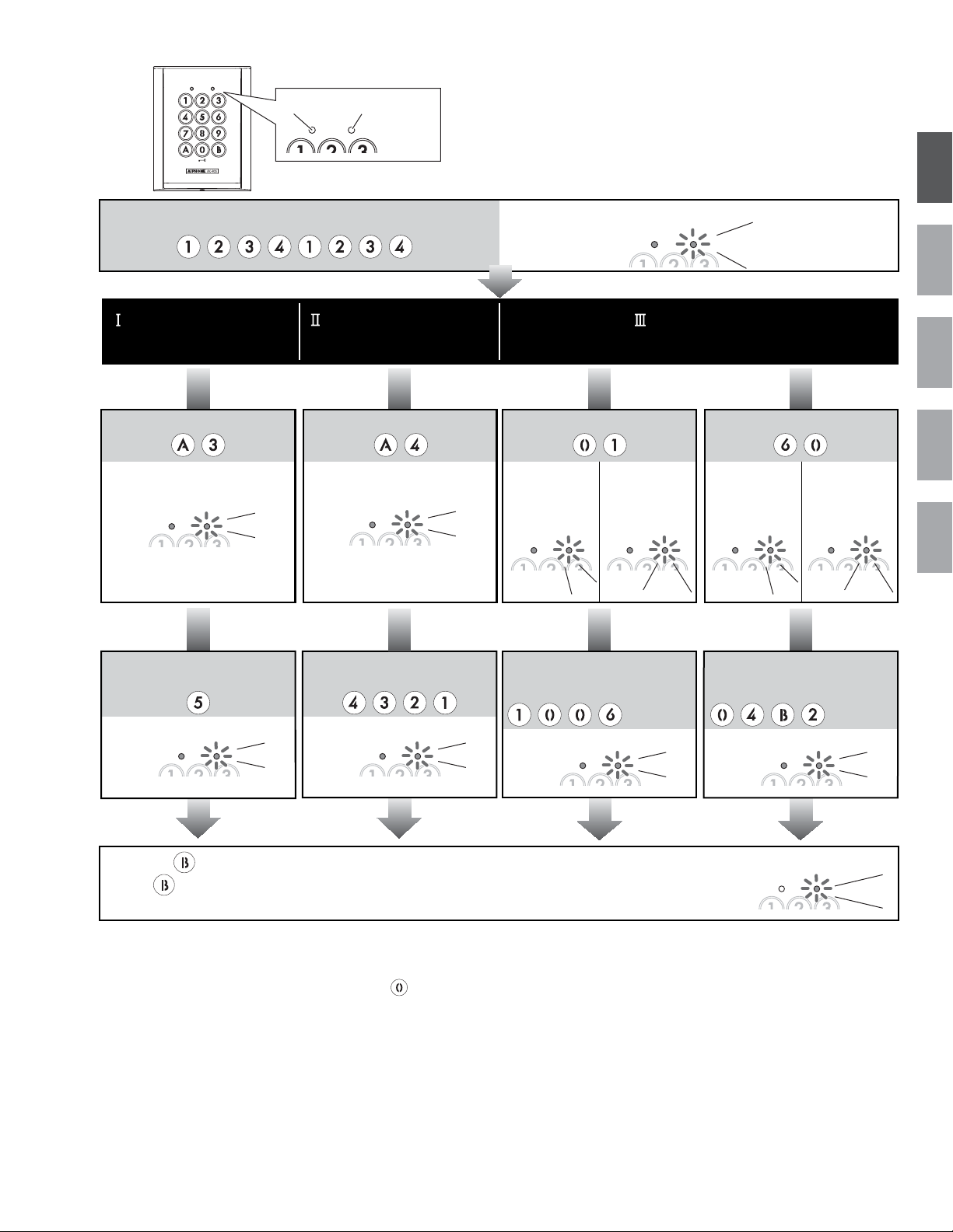
Orange (L) Green (R)
The result of each operation is indicated by the
lighting up of the LED indicators on the upper section
of the unit, and by the sounding of the buzzer.
English
Input the master code twice.
(Default: )
Setting the code length
(Default: 4 digits)
Input the setting code.
Illumination Blinking
Bleep
Setting the master code
(Default㧦1234)
Input the setting code.
Illumination Blinking
Bleep
(orange)
Illumination
(green)
Blinking
Setting the code
group 1
00 - 59 60 - 99
Inputting of user number (ex.: 01)
When a user code
that has already
been set is selected
Blinks
Illumination
Bleep
twiceBlinkingIllumination
Bleep,
Bleep
Inputting of user number (ex.: 60)
Bleep, Bleep
group 2
Bleep
When a user code
that has already
been set is selected
Blinks
twiceBlinkingIllumination Illumination
Bleep,
Bleep
Français Deutsch Español
Nederlands
Inputting of code length (ex.: 5 digits)
4, 5, or 6 digits
Inputting of new master code
(ex.: 4321)
Inputting of code (ex.: 1006)
* Numbers 0
-
9 and the
letters A and B can be used
Illumination Blinking
Beep
-
When the key is pressed, the green LED lights up, the buzzer beeps twice, and the system exits the setting mode.
Illumination Blinking
Beep
Illumination
Blinking Illumination Blinking
Beep Beep
Inputting of code (ex.: 04B2)
* Numbers 0
letters A and B can be used
(If the key is included in the user code and the master code, the system does not exit the setting mode.)
- You can continue the setting up operation by entering an arbitrary setting code.
· The set code will be saved in
memory, even if the code length
is changed. However , c odes of
differ ent l engths cannot be used.
· W hen the code length has been
changed, the master code r eturns
to the default val ue (if the num ber
of digits in the code i s 4, 5, or 6,
the master code i s 1234, 12345,
or 123456 respectively).
· Please note that the shift to the
setting mode can be performed
during timer-linked unlocking.
However, if " " is included in
the master code, the door will
be unlocked, and the shift to
the setting mode will not be
able to be performed.
· The same code cannot be set
for both the user code and the
master code (the previously set
code has priority).
· Do not set simple codes, such
as 1111.
· We recommend that you
change the default master
code.
· To make the set user code invalid, press 0000 (when 4 digits are
used), 00000 (when 5 digits are used), or 000000 (when 6 digits are
used). Code numbers which contain only "0" cannot be set as user
codes.
· As the factory pre-setting master code is 1234, 1234 (when 4 digits
are used), 12345 (when 5 digits are used), and 123456 (when 6
digits are used) cannot be set as user codes.
· Do not set simple codes, such as 1111.
* The same code cannot be set for both the user code and the
master code. The previously set code has priority.
Indicator
goes out
-
9 and the
Blinking
Bleep,
Bleep
6
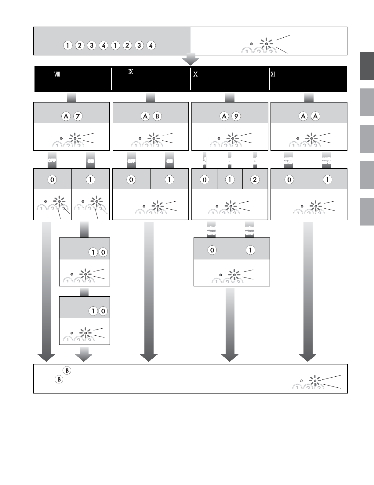
Page 8
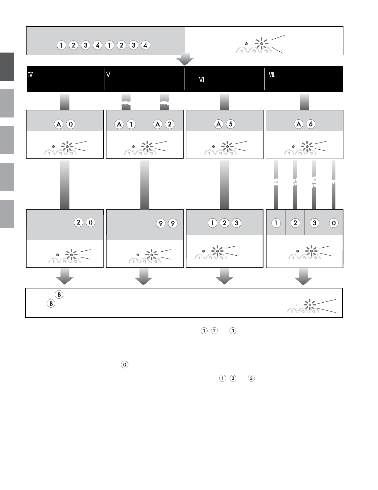
Input the master code twice.
(Default : )
(orange)
Illumination
(green)
Blinking
Bleep, Bleep
English
Setting the key illumination time
FrançaisDeutschEspañol
Inputting of illumination time
Nederlands
(ex.: 20 seconds)
10 - 99
Indicator is lit up at all times: 00
(Default: 10 Sec.)
Input the setting code.
Illumination Blinking
Bleep
Illumination Blinking
Beep
Setting the relay output time
(Default: 3 Sec.)
When setting relay 1When setting relay 1 When setting relay 2When setting relay 2
Input the setting code. Input the setting code.
Illumination Blinking
Bleep
Inputting of relay output time
(ex.: 99 seconds)
01 - 99
Latched () : 00
Illumination Blinking
Beep
Illumination IlluminationBlinks three times Blinking
Reset Settings
Input the setting code.
Illumination Blinking Illumination Blinking
Bleep Bleep
Bleep, Bleep, Beep
(Default: OFF)
Input the setting code.
During lockout
entry output
entry output
During lockout
and forced
and forced
entry output
entry output
During
During
Lockout
Lockout
During forced
During forced
External output setting
OFFOFF
Beep
-
When the key is pressed, the green LED lights up, the buzzer beeps twice, and the system exits the setting mode.
Indicator
goes out
(If the key is included in the user code and the master code, the system does not exit the setting mode.)
- You can continue the setting up operation by entering an arbitrary setting code.
· () If the latched status has
been set and the door is
unlocked, it will not be locked
again until the user code is
entered (or the request to
exit/entry button is pressed, or
the key is pressed while
timer-linked unlocking is set).
· When the door is unlocked
during relay outputting
(including when latched), the
system cannot be switched to
the setting mode.
· If the power is tur ned off and
the , , and keys ar e
pressed si m ul taneously w hile the
unlock 1 input status is active
(shor t circuit between ter m inals
PB1 and C), the settings can be
returned to their default values by
turning the power back on and
pressing the , , and
keys simultaneousl y for 3
seconds.
· W hen setti ng the exter nal output,
do not set the r elay 2 output to be
latched.
Blinking
Bleep,
Bleep
7
Page 9
Input the master code twice.
(Default : )
(orange)
Illumination
(green)
Blinking
Bleep, Bleep
English
Lockout
(Default: OFF)
Input the setting code.
Bleep Bleep
OFFONOFF
Illumination Blinking Illumination Blinking
Beep
Inputting the number of operations
(ex.㧦10 times)
10 -99
Illumination Blinking
ON OFFOFF ONON
Bleep
Bleep
Auto-relock
(Anti-tailgate)
(Default: OFF)
Input the setting code.
Timer-linked unlocking setting
(Default: relay 1, OFF)
Input the setting code.
Illumination BlinkingIllumination BlinkingIllumination Blinking Illumination Blinking
BleepBleep
Relays 1 and 2
Relays 1 and 2
are both linked
are both linked
0 key illumination OFF
0 key illumination OFF
while timer is on
while timer is on
Only relay 1
Only relay 1
is linked
is linked
Illumination BlinkingIllumination Blinking Illumination Blinking
Illumination Blinking
Only relay 2
Only relay 2
is linked
is linked
BleepBeep
0 key illumination ON
0 key illumination ON
while timer is on
while timer is on
Beep
Operation sound settings
(Default: ON)
Input the setting code.
Operation
Operation
tone OFF
tone OFF
Operation
Operation
tone ON
tone ON
Beep
Français Deutsch Español
Nederlands
Inputting length of time in "Lockout" mode
(Ex.: 10 seconds)
10 - 99
Illumination Blinking
Beep
-
When the key is pressed, the green LED lights up, the buzzer beeps twice, and the system exits the setting mode.
Indicator
goes out
(If the key is included in the user code and the master code, the system does not exit the setting mode.)
- You can continue the setting up operation by entering an arbitrary setting code.
· When the relay 1 output time is
set to latched output, the
auto-relock function is
disabled.
· When the auto-relock function
is turned on, the unlock
function of the request to
exit/entry button of relay 2 is
disabled.
· If the 0 key illumination function
is turned on while the timer is
on, only the 0 key illumination
will light up, even if the "key
illumination time setting" is set
to "Indicator is continually lit".
Blinking
Bleep,
Bleep
8
Page 10

OPERATIONS
A. Unlocking of user code
When the registered user code has been input using the
English
FrançaisDeutschEspañol
Nederlands
keypad (between 4 and 6 digits), the LED indicator (group
1: orange, group 2: green) lights up, the buzzer sounds,
and the electric door strike is unlocked.
ex.): group 1
1006
Orange LED lights up (during relay1 operation)
• The time interval during which the button must be
pressed is approximately 10 seconds. If the time
interval exceeds approximately 10 seconds, the input
value will be cleared.
• If you make a mistake when inputting the user code,
input the user code again.
• When the "Lockout" function has been set, the release
function is locked and the input operation is disabled for
the specified time (10 ~ 99 seconds) if invalid codes are
input a set number of times (10 ~ 99 times). (Reference:
"Lockout".) During this time, the key illumination will
blink 4 times, the LED (orange) indicator will blink for
the set deactivation time, and the buzzer will sound for
approximately 3 seconds.
B. Timer-linked unlocking
When the timer-linked unlocking function is active, the
door can be unlocked by pressing the
set time, while the timer is linked.
key illumination lights up when the timer is
The
activated by performing the setting.
C. Unlocking using the request to exit/entry button
When leaving the premises, you can activate the electric
door strike by pressing the request to exit/entry button
connected to the unit. Pressing request to exit/entry
button 1 releases relay 1, and pressing request to exit/
entry button 2 releases relay 2.
• When the door is unlocked using the request to exit/
entry button, the LED will not light up and the buzzer
will not sound.
Green LED lights up (during relay2 operation)
group 2
04B2
key during the
TECHNICAL PRECAUTIONS
• Operating temperature: Between -20°C and 60°C(-4˚F to
140˚F)
• Cleaning: Clean the unit with a soft cloth dampened with
a neutral household cleanser. Do not use any
abrasive cleanser or cloths.
• The unit is weather resistant. However do not spray
high pressure water on access control keypad directly.
Excessive moisture may cause problems with the unit.
• Press and release the
simultaneously when this unit does not work.
, , , and keys
)The LEDs (orange and green) will blink and the buzzer
will sound, and then resetting will take place. (The settings
do not return to their default values.)
• If resetting does not work, contact the service technician
who installed the unit.
SPECIFICATIONS
• Power supply: 12 ~ 24V AC
12 ~ 24V DC
• Power consumption: DC: Max. 70mA
AC: Max. 100mA
• Dimensions:
BeepBeep
AC-10S: 125(H) × 98(W) × 33(D)mm
H 4-15/16” x W 3-7/8” x D 1-5/16”
AC-10F: 132(H) × 117(W) × 5(D)(recess: 29)mm
H 5-3/16” x W 4-5/8” x D 3/16”, recess 15/16”
Flush mount back box: 100(H) × 85(W) × 45(D)mm
H 3-15/16 x W 3-1/3 x D 1-3/4”
• Weight: AC-10S: approx. 600g (1.3 lbs)
AC-10F: approx. 670g (1.5 lbs)
• IP: IP54
• Number of relay circuits: 2
• Relay contact: N/O, N/C
• Relay contact capacity: 24V DC, 3A (resistive load)
1A (inductive load)
24V AC, 3A (resistive load)
1A (inductive load)
WARRANTY
Aiphone warrants its products to be free from defects of material
and workmanship under normal use and service for a period of
one year after delivery to the ultimate user and will repair free
of charge or replace at no charge, should it become defective
upon which examination shall disclose to be defective and under
warranty. Aiphone reserves unto itself the sole right to make
the final decision whether there is a defect in materials and/or
workmanship; and whether or not the product is within the
warranty. This warranty shall not apply to any Aiphone product
which has been subject to misuse, neglect, accident, or to
use in violation of instructions furnished, nor extended to units
which have been repaired or altered outside of the factory. This
warranty does not cover batteries or damage caused by batteries
used in connection with the unit. This warranty covers bench
repairs only, and any repairs must be made at the shop or place
designated in writing by Aiphone. Aiphone will not be responsible
for any costs incurred involving on site service calls. Aiphone will
not provide compensation for any loss or damage incurred by the
breakdown or malfunction of its products during use, or for any
consequent inconvenience or losses that may result.
FCC
This device complies with Part 15 of the FCC Rules.
Operation is subject to the following two conditions: (1) this
device may not cause harmful interference, and (2) this
device must accept any interference received, including
interference that may cause undesired operation.
9
Page 11

Français
PRECAUTIONS
Mesures générales d'interdiction Interdiction de démonter l'appareil
Précautions générales
AVERTISSEMENT
(Le non-respect de cet avertissement risque d'entraîner
des blessures graves,voire mortelles)
1.
Ne pas brancher de source d'alimentation non spécifiée aux bornes
+ et -, et ne pas brancher deux sources d'alimentation en parallèle
sur une entrée unique. Vous risqueriez de provoquer un incendie,
un dysfonctionnement du système, ou d'endommager l'unité.
2.
L'appareil ne résiste pas aux explosions. N'installez et
n'utilisez jamais ce produit à proximité de gaz ou de matériaux
inflammables. Un incendie ou une explosion peut survenir.
3. Ne pas démonter ni modifier l'unité. Vous risqueriez de
provoquer un incendie ou une décharge électrique.
English
3.
Avant de brancher le bloc d'alimentation, vérifier que les fils ne sont pas croisés ou en
court-circuit. Vous risqueriez de provoquer un incendie ou une décharge électrique.
4.
Ne pas installer l'appareil à aucun des emplacements suivants pour éviter tout
risque d'incendie, de décharge électrique ou d'endommagement de l'appareil.
Endroits exposés à la poussière, à la graisse et aux produits chimiques.
*
* Endroits où le degré d'humidité est élevé, tels qu'une
salle de bains, une cave, une serre, etc.
* Endroits où la température est très basse, tels qu'une
zone réfrigérée ou face à un climatiseur.
* Endroits exposés à la vapeur ou à la fumée (à
proximité de plaques chauffantes ou de cuisson).
Lorsque des appareils occasionnant des parasites se trouvent à
*
proximité (interrupteur crépusculaire, onduleur, appareils électriques).
Français Deutsch Español
ATTENTION
(Le non-respect de cet avertissement risque d'entraîner
des blessures ou des dégâts matériels)
1.
Pour fixer l'unité au mur, choisir un endroit adapté
où elle ne risque pas de subir des secousses ou des
chocs. Sinon, vous risquez de provoquer des blessures.
2.
Ne réaliser aucune connexion douille terminale de fil
lorsque l'appareil est branché, sous peine de provoquer
une décharge électrique ou d'endommager l'unité.
TABLE DES MATIERES
AIDE MEMOIRE DES PROGRAMMATIONS ENREGISTREES
AVERTISSEMENT ……………………………………… 10
CONTENU DE L'EMBALLAGE ………………………… 10
DESCRIPTIONS ………………………………………… 11
PROCEDURE DE MONTAGE ………………………… 11
RACCORDEMENT ET DISTANCE DE CABLAGE…… 12
…1
PRECAUTIONS GENERALES
1.
Ce produit étant une unité de contrôle de gâche électrique, il
ne doit pas être utilisé en tant que dispositif anti-criminalité.
2.
Le poste de porte est étanche. Cependant, ne pas vaporiser
de l'eau à haute pression directement sur celui-ci. Cela
risquerait en effet de provoquer une panne de l'appareil.
3.
L'unité sera hors-service pendant une coupure de courant.
4.
En ce qui concerne les dispositifs d'autres fabricants (tels
que les capteurs, les détecteurs,les gâches de porte) utilisés
avec ce système, conformez-vous aux Spécifications et aux
Conditions de garantie des fabricants ou des distributeurs.
FONCTIONS
UTILISATION …………………………………………… 17
PRECAUTIONS TECHNIQUES ……………………… 17
CARACTERISTIQUES TECHNIQUES ………………… 17
GARANTIE ……………………………………………… 17
GABARIT DE L'ETRIER DE FIXATION POUR L'INSTALLATION DU AC-10S (ECHELLE 1:1)
PROGRAMMATION …………………… 13
…42
Nederlands
CONTENU DE L'EMBALLAGE
AC-10S AC-10F
Appareil
Etrier de
fixation
Vis de
fixation
Tournevis
spécial
Notice
d'utilisation
Appareil
Boîtier
d'encastrement
Tournevis
spécial
Notice
d'utilisation
10
Page 12

DESCRIPTIONS
A
98mm
11.5mm
3.5mm
49mm
42.5mm
55mm
68.5mm
Entrée de câble
15mm
64mm
12
English
1
3
FrançaisDeutschEspañol
4
PROCEDURE DE MONTAGE
AC-10S
1. Percer des trous dans le mur de manière à ce qu'ils
correspondent en taille et en nombre au vis de fixation.
2.
Fixer l'étrier de fixation sur le mur en utilisant les vis de fixation d'installation.
3.
Fixer le clavier sur l'étrier de fixation en utilisant le tournevis
spécial ainsi que la vis de fixation spéciale d'installation.
C-10S
55mm
Nederlands
4
1 LED (Orange)
2
3
2 LED (Verte)
3 Touches (jaune)
4 Vis de fixation spéciales pour une
installation sur façade
4
AC-10F
1.
Dévisser la façade du AC-10F en utilisant le tournevis spécial fourni.
2. Fixer le boîtier d'encastrement en affleurement du mur.
3. Fixer le clavier sur la boîtier d'encastrement en
affleurement en utilisant le tournevis spécial ainsi que les
vis spéciales d'installation.
AC-10F
85mm
Câble
Trous supplémentaires
de vis de fixation
1
Mur
Mur
3
EncliquetageEncliquetage
2
Boîtier d'encastrement
100mm
45mm
Quand cet appareil doit être utilisé avec la JF-DV, veuillez vous référer à l'illustration ci-dessous au moment de son installation.
Merci de vous reporter à :GABARIT DE L'ETRIER DE FIXATION POUR L'INSTALLATION DU AC-10S (ECHELLE 1:1) (page 42).
1. Platine JF-DV
173mm
2. Positionnement des trous de perçage
Veuillez vous référer à l'illustration
ci-dessous au moment de percer
les trous. S'assurer que l'entrée
de câble se trouve dans les limites
de la zone ombrée indiquée sur
l'illustration ci-dessous.
3. Position de l'étrier de fixation
Veuillez vous référer à
l'illustration ci-dessous au
moment de fixer l'étrier de
fixation.
Fixer le clavier à l'étrier de fixation
murale en le repoussant dans celui-ci.
Serrer la vis de fixation pour conclure
l'installation.
( )
Etant donné qu'il existe des trous de
drainage à la base de l'appareil JF-DV, ne
pas obturer l'espace entre la JF-DV et le
clavier codé.
4. Installation
98mm
11
42.5mm
55mm
49mm 49mm
Trou pour l'entrée
de câble
5mm
( )
Page 13

CÂBLAGE, DISTANCE DE CÂBLAGE
Portail automatique
ou
Ventouse
électromagnétique
Gâche
électrique
Borniers de sortie
Vue arrière du AC-10S
Connexion du relais 1 seulement
Relais
Relais
2
Alimentation
Alimentation
Entre 12 et 24 V c.a.
Entre 12 et 24 V c.c.
AD
2
2
B
2
2
2
C
Bouton de
relais 1
Bouton de
sortie pour
sortie pour
VV
Bouton de sortie · Horloge
Surcharge minimum: 100 mV c.c, 0,1 mA ou supérieur
·
· Capacité de contact: 3 V c.c, 0,1 A ou supérieur
Exemple de connexion d'une
gâche électrique (N/O)
relais 2
PB2PB1
Alimentation
Bouton de sortie
Bouton de sortie
Horloge
Commun Horloge
(Distance de câblage)
Alimentation
c.a./c.c.12 ~ 18V
A
c.a./c.c.18 ~ 24V
B
C
La distance de connexion dépendra des
caractéristiques de la gâche électrique, des
relais ou de la ventouse électromagnétique
D
à connecter. Pour déterminer les limites de
fonctionnement, veuillez vous référer aux
caractéristiques de chaque borne.
Relais 1 du groupe utilisateur 1 Relais 2 du groupe utilisateur 2
Contact N/F
TC
NO1
Exemple de connexion d'un
portail automatique (N/O)
C1
Contact N/O Contact N/O
Relais
24 V c.c, 3 A (charge résistive) 1A (charge inductive)
24 V c.a, 3 A (charge résistive) 1A (charge inductive)
· Surcharge minimum: 5 V c.c, 100 mA ou supérieur
(moins de)
-
- 300m
NC1
NO2
Exemple de connexion d'une
ventouse électromagnétique (N/F)
diamètre 6/10-8/10ème LYT
100m
300m
300m
Contact N/F
C2
NC2
English
Français Deutsch Español
Nederlands
C2
NC2
Alimentation
TC
NO1
C1
VV
2
NP
2
NP
Bouton de sortie
2
NC1PB2PB1
NP
Transformateur en C.A.
NO2
Gâche électrique
Relais 1: Portail automatique (contact N/O), Relais 2: Gâche électrique (contact N/O)
TC
NO1
Alimentation
Puissance
Entre 12 et 24 V c.a.
Entre 12 et 24 V c.c.
Bouton de
sortie relais 1
Bouton de
sortie relais 2
Horloge
VV
2
NP
2
NP
2
NP
2
NP
2
N.C
PB2
C1
NP
Portail automatique
NO1
2
NC1 NO2
2
Auto-reverrouillage / sortie externe quand une porte forcée est actionnée
(connexion d'un détecteur)
· Pour commander la fonction d'auto-reverrouillage, un détecteur est exigé
(à se procurer localement).
C
· Le bouton de sortie pour le relais 2 ne peut pas être utilisé tandis que la
fonction d'auto-reverrouillage est actionnée.
NC1
C1
NP
Portail automatique
C2
NC2PB2PB1
NP
Transformateur en C.A.
NO2
NO1
ouou
Paramétrage de sortie externe
C2
Seul le raccordement à la borne
du relais 2 est possible.
Alarme, Sécurité
Gâche électrique
C1
2
NC1 NO2N
NP
Alimentation
Ventouse
électromagnétique
PS
C2
12
Page 14

FONCTIONS PROGRAMMATION
Cette section explique les paramétrages de chaque fonction, y compris le code maître, le code d'utilisateur, les bips et les Leds.
Au sujet du mode de paramétrage:
Saisir deux fois le code maître pour rentrer en mode programmation, puis saisir le code de paramétrage pour
exécuter la fonction désirée. Après paramétrages de celle-ci, saisir un nouveau code de paramétrage pour continuer
la programmation. Appuyer sur
English
Rubriques de paramétrage Limites de paramétrage
Programmation du nombre de termes
Modifier le nombre du code maître et du code d'utilisateur.
)
Le code maître et le code d'utilisateur doivent avoir le même nombre de
FrançaisDeutschEspañol
termes.
Programmation du code maître
Saisir un code maître en utilisant 4 ou 5 ou 6 chiffres (alpha ou numérique)
pour rentrer en mode programmation.
) Le nombre de chiffres dans le code peut être paramétré en choisissant
le nombre de termes.
Programmation du code pour le groupe d'utilisateur 1
Programmer le code d'ouverture pour le groupe d'utilisateur 1.
) Le nombre de chiffres dans le code peut être paramétré.
Programmation du code pour le groupe d'utilisateur 2
Programmer le code d'ouverture pour le groupe d'utilisateur 2.
) Le nombre de chiffres dans le code peut être paramétré.
Programmation de la durée d'éclairage des touches
Paramétrer la durée pendant laquelle les touches seront allumées après une impulsion.
Programmation de la temporisation du relais 1
Paramétrer la temporisation du relais 1.
Programmation de la temporisation du relais 2
Nederlands
Paramétrer la temporisation du relais 2.
Remise à zéro des programmations
Ramène tous les paramétrages sur leurs valeurs par défaut.
Paramétrage de sortie externe
Le système d'alarme ou de sécurité connecté au câblage du relais 2 sera activé quand le blocage
* ou la porte forcée * est effectuée. * Blocage : Se référer à VIII ci-dessous. * Porte forcée: Cette
fonction est programmée le détecteur d'ouverture/fermeture de porte (N/F) qui est connecté à PB2
et à C, et est exécutée en ouvrant la porte sans mise en fonction du clavier. (Par exemple, la porte
d'une manière incorrecte, un déverrouillage manuel, etc.)
*) S'il y a existe une façon d'ouvrir la porte sans mettre le clavier en fonction, comme dans le cas d'un
déverrouillage manuel, ne pas effectuer de paramétrage de sortie externe pour une porte forcée.
Blocage
Si plusieurs codes d'accès incorrects ont été saisie , la saisie de code est
invalidée pendant une durée préprogrammée.
· Lorsque "Blocage" est activé, la LED (orange) et le clavier codé clignotent
tandis que la sonnerie retentit pendant 3 secondes. Ceci est juste un son
pour vous avertir que la fonction a été activée. Il ne s'agit pas d'une sonorité
d'avertissement. Si vous voulez qu'un avertissement retentisse, veuillez
employer la fonction de sortie externe pour activer un dispositif d'alarme
disponible dans le commerce.
· L'ouverture de la porte fonctionnera quand le bouton de sortie/entrée est
pressé, même pendant que la fonction "Blocage" fonctionne.
Auto-reverrouillage (anti-accès)
Si un détecteur (N/F) est utilisé, il coupera la temporisation du relais 1 ,ceci
empêchant l'entrée d'un tiers non autorisé.
Programmation du déverrouillage lié à l'horloge
Le système peut être réglé pour activer la porte en appuyant sur la
touche
diodes électroluminescentes et l'avertisseur sonore après l'ouverture
sont identiques à celles utilisées pour exécuter l'ouverture par le code
d'utilisateur. Quand le clavier est lié à l'horloge, l'ouverture peut être exécuté
en utilisant le code d'utilisateur et le bouton de sortie. Quand la sortie de
verrouillage est exécutée pour les paramétrages de relais, le relais actionne
sur "marche/arrêt" à chaque fois que la touche
, si le contact horloge est fermé. Les opérations pour les
Programmation de tonalité de fonctionnement
Paramétrage des bips d'utilisation ON/OFF.
• La programmation peut être sauvegardé lors d'une coupure de courant.
• Le système ne peut pas rentrer en programmation dès lors qu'un relais est activé.
•
Quand vous êtes en programmation et qu'aucune opération n'est exécutée pendant approximativement 120 secondes, le système
annulera le mode de programmation. (Si une touche est pressée pendant ce temps, l'horloge recommencera un nouveau cycle.)
•
En mode programmation, ni le bouton de sortie ni la touche liée à l'horloge ne peuvent être actionnés, ainsi que le code utilisateur.
•
Le volume (le son de test, le son de commande, etc.) à partir de l'appareil principal peut être plus faible selon le mode de montage.
1
:
13
Le bouton de demande de sortie/d'entrée pour le relais 2 ne peut pas être utilisé quand la fonction d'auto-reverrouillage
est utilisée. La sortie du relais 2 est seulement possible quand le déverrouillage du code d'utilisateur est exécuté.
pour quitter le mode de programmation.
4, 5 ou 6 chiffres 4 chiffres
1
Touches utilisables: 0 - 9, A, B
Nombre de codes: 60
Touches utilisables: 0 - 9, A, B
Nombre de codes: 40
Touches utilisables: 0 - 9, A, B
Durée d'éclairage: 10 à 99
secondes, ou allumage permanent
Temporisation: 1 à 99
secondes, ou bistable
Temporisation: 1 à 99
secondes, ou bistable
--
· OFF
· Blocage avec sortie
externe
· Porte forcée avec sortie
externe
· Blocage et porte forcée
avec sortie externe
ON/OFF
Nombre d'appui sur touche
incorrect:
10 à 99
Durée de blocage:
10 à 99 secondes
ON/OFF OFF
)1
Relais programmé: Relais 1
Touche 0 éclairée: ON/OFF
est pressée.
ON/OFF ON
admissibles
Relais 2
Relais 1 et 2
Valeur par
défaut
paramétrage
1234
-
-
10 sec.
3 sec.
3 sec.
OFF
OFF
Relais programmé:
Relais 1
Touche 0 éclairée:
OFF
Code de
-
-
Page 15

Orange (G) Vert (D)
Le résultat de chaque opération est indiqué par
l'éclairage des Led's sur la partie supérieure de
l'appareil, et par le retentissement de Bip sonore.
English
Saisir deux fois le code maître.
(Valeur par défaut: )
Programmation du nombre de termes
(Valeur par défaut: 4 chiffres )
Programmation du code maître
(Valeur par défaut: 1234)
Saisir le code de paramétrage. Saisir le code de paramétrage.
S'allume Clignote
Bip
S'allume Clignote
Bip
(orange)
S'allume
(vert)
Clignote
Programmation du code utilisateur
Groupe 1
00 - 59 60 - 99
Saisie l'adresse d'utilisateur (ex.: 01)
Quand l'adresse
utilisateur a déjà
été programmé
Clignote
Clignote S'allume
S'allume
Bip
deux fois
Bip,
bip
Saisie l'adresse d'utilisateur (ex.: 60)
Bip, bip
Groupe 2
Quand l'adresse
utilisateur a déjà
été programmé
Clignote
Clignote S'allume S'allume
Bip
deux fois
Bip,
bip
Français Deutsch Español
Nederlands
Saisie le nombre de termes (ex: 5 chiffres)
4, 5 ou 6 chiffres
Saisir un nouveau code
maître (ex: 4321)
Saisie du code (ex.: 1006)
*
Les nombre 0 - 9 et les lettres
A et B peuvent être utilisés
S'allume Clignote
Biip
-
Quand la touche est pressée, la led verte s'allume, deux Bip sonore retentisse , et le système quitte le mode de programmation.
S'allume Clignote
Biip
S'allume
Clignote S'allume Clignote
Biip Biip
(Si la touche est comprise dans le code d'utilisateur et le code maître, le système ne quitte pas le mode programmation.)
-
Vous pouvez continuer les opérations de programmation en saisissant un autre code de paramétrage.
·
· Le code programmé ser a
sauvegardé dans l a m ém oire,
même si le nombre de termes
est changé. C ependant, des
codes de différ ents ter me ne
peuvent pas êtr e utilisés.
· Quand l e nom br e de ter mes a été
changé, le code maîtr e revient
sur sa val eur par défaut (si le
nombre de chi ffres dans le code
est 4, 5 ou 6, le code maîtr e sera
1234, 12345 ou 123456
respectivement).
Veuillez noter que le passage en
mode programmation peut être
exécuté pendant le déverrouillage lié
à l'horloge. Cependant, si " " est
compris dans le code maître, la porte
sera libérée et le passage en mode
programmation ne sera pas exécuté.
·
Le même code ne peut pas être
programmé comme code d'utilisateur
et code maître. Le code programmé
précédemment a la priorité.
· Ne pas paramétrer des codes
simples, tels que 1111.
·
Nous vous recommandons de changer
le code maître de maître par défaut.
· Pour rendre invalide le code utilisateur paramétré, rentrer en
programmation, taper son adresse puis appuyer sur 0000 (quand 4
chiffres sont utilisés), 00000 (quand 5 chiffres sont utilisés) ou
000000 (quand 6 chiffres sont utilisés). Les numéros de code qui ne
contiennent que des "0" ne peuvent pas être paramétrés comme
codes utilisateurs.
· Etant donné que le code maître préprogrammé en usine est 1234
(quand 4 chiffres sont utilisés), 12345 (quand 5 chiffres sont
utilisés) ou 123456 (quand 6 chiffres sont utilisés) ceux-ci ne
peuvent pas être utilisés comme codes d'utilisateur.
· Ne pas paramétrer des codes simples, tels que 1111.
* Le même code ne peut pas être programmé comme code
d'utilisateur et code maître. Le code programmé
précédemment a la priorité.
Saisie du code (ex.: 04B2)
*
Les nombre 0 - 9 et les lettres
A et B peuvent être utilisés
Le témoin
s'éteint
Clignote
Bip,
bip
14
Page 16

English
FrançaisDeutschEspañol
(orange)
Saisir deux fois le code maître.
S'allume
(Valeur par défaut: )
Programmation de la durée
d'éclairage des touches
(Valeur par défaut: 10 sec.)
Saisir le code de paramétrage. Saisir le code de paramétrage. Saisir le code de paramétrage.
Programmation de
temporisation des relais
Retour configuration usine
(Valeur par défaut: 3 sec.)
En programmant le relais 1
En programmant le relais 1
Saisir le code de paramétrage. Saisir le code de paramétrage.
En programmant le relais 2
En programmant le relais 2
(vert)
Clignote
Bip, bip
Programmation de sortie externe
(Valeur par défaut: Désactivé )
Saisie de la durée d'éclairage
Nederlands
(ex.: 20 secondes)
10 - 99
Eclairage permanent: 00
-
-
S'allume Clignote
Bip
S'allume Clignote
Bip
S'allume Clignote S'allume Clignote
Bip Bip
Blocage avec
Blocage avec
sortie externe
sortie externe
Saisie de la durée de temporisation du
relais (ex: 99 secondes)
01 - 99
Bistable () : 00
S'allume Clignote
Biip
S'allume Clignote
Biip
S'allume S'allume Clignote trois fois Clignote
Bip, bip, biip
Quand la touche est pressée, la led verte s'allume, deux Bip sonore retentisse , et le système quitte le mode de programmation.
(Si la touche est comprise dans le code d'utilisateur et le code maître, le système ne quitte pas le mode programmation.)
Vous pouvez continuer les opérations de programmation en saisissant un autre code de paramétrage.
Porte forcée
Porte forcée
avec sortie
avec sortie
externe
externe
Le témoin
s'éteint
Blocage et porte
Blocage et porte
forcée avec
forcée avec
sortie externe
sortie externe
Biip
Clignote
Bip,
OFFOFF
bip
15
· () Si le mode bistable a été
programmé et que la porte est
libérée, elle ne sera pas
reverrouillée tant que le code
utilisateur ne sera pas saisi (ou
que le bouton de sortie ne soit
pressé ou que la touche
ne soit pressée pendant le
déverrouillage liée à l'horloge).
· Quand un relais est enclenché,
le système ne peut pas rentré
en mode programmation.
· Si l'alimentati on est coupé et que
les touches , et sont
pressées simultanément et que
les bor nes PB1 et C sont reliées,
vous pouvez reveni r en
configur ation usine en
rétablissant l' alimentati on et en
appuyant simultanément sur les
touches , et pendant 3
secondes.
· Quand l a sortie externe est
paramétrée, l a sortie du relais 2
ne peut pas être utilisée en mode
bistabl e.
Page 17

Saisir deux fois le code maître.
(Valeur par défaut: )
(orange)
S'allume
(vert)
Clignote
Bip, bip
English
Blocage
(Valeur par défaut: OFF)
Auto-reverrouillage
(anti-accès)
(Valeur par défaut: OFF)
Programmation du déverrouillage
lié à l'horloge
(Valeur par défaut: Relais 1, désactivé)
Programmation des bips
de fonctionnement
(Valeur par défaut: ON)
Saisir le code de paramétrage. Saisir le code de paramétrage. Saisir le code de paramétrage. Saisir le code de paramétrage.
S'allume Clignote S'allume Clignote S'allume Clignote S'allume Clignote
Bip Bip
OFFONOFF
S'allume Clignote S'allume Clignote
Biip
ON OFFOFF ONON
Bip
Les relais 1 et 2
Les relais 1 et 2
seront activés
seront activés
La touche 0 est
La touche 0 est
éteinte pendant que
éteinte pendant que
l'horloge est activée
l'horloge est activée
Seul le relais 1
Seul le relais 1
sera activé
sera activé
S'allume Clignote S'allume Clignote S'allume Clignote
BipBip
Seul le relais 2
Seul le relais 2
sera activé
sera activé
BipBiip
La touche 0 est
La touche 0 est
allumée pendant que
allumée pendant que
l'horloge est activée
l'horloge est activée
Bip de fonctionnement
Bip de fonctionnement
désactivé
désactivé
Bip de fonctionnement
Bip de fonctionnement
activé
activé
Biip
Saisie du nombre de touche
(ex: 10 fois)
10 -99
S'allume Clignote
Bip
S'allume Clignote
Biip
Français Deutsch Español
Nederlands
Saisie de la durée du mode "Blocage"
(ex: 10 secondes)
10 - 99
S'allume Clignote
Biip
-
Quand la touche est pressée, la led verte s'allume, deux Bip sonore retentisse , et le système quitte le mode de programmation.
(Si la touche est comprise dans le code d'utilisateur et le code maître, le système ne quitte pas le mode programmation.)
-
Vous pouvez continuer les opérations de programmation en saisissant un autre code de paramétrage.
· Quand la temporisation du
relais 1 est paramétrée en
bistable, la fonction
d'auto-reverrouillage est
invalidée.
· Quand la fonction
d'auto-reverrouillage est
activée, le bouton de sortie du
relais 2 est invalidé.
· Si la fonction d'éclairage de
touche 0 est activée pendant
que l'horloge est en fonction,
seule la touche 0 s'allume
même si "la programmation de
durée d'éclairage de touche"
est validé en continue.
Le témoin
s'éteint
Clignote
Bip,
bip
16
Page 18

UTILISATION
A. Déverrouillage par code d'utilisateur
Quand le code d'utilisateur enregistré a été saisi (entre
English
FrançaisDeutschEspañol
Nederlands
4 et 6 chiffres), la led (groupe 1: orange, groupe 2: vert)
s'allume, et un bip sonore retentit et la gâche est libérée.
ex.) Groupe 1
1006
La led orange s'allume (pendant le fonctionnement du relais 1)
• L'intervalle de temps pendant lequel la touche
bouton doit être pressée est approximativement
de 10 secondes. Si l'intervalle de temps dépasse
approximativement 10 secondes, la valeur saisie sera
effacée.
• Si vous faites une erreur en entrant votre code
d'ouverture, resaisir celui-ci de nouveau.
• Quand la fonction "Blocage" a été paramétrée, la
fonction de libération est verrouillée et l'opération de
saisie est interdite pendant la durée indiquée (10 ~
99 secondes) si des codes incorrects sont saisis un
nombre de fois paramétré (10 ~ 99 fois). (Référence:
"Fermeture".) Pendant ce temps, l'éclairage de
la touche clignotera 4 fois, le témoin de la diode
électroluminescente (orange) clignotera pendant la
durée de désactivation paramétrée, et l'avertisseur
sonore retentira pendant approximativement 3
secondes.
B. Déverrouillage lié à l'horloge
Quand la fonction de déverrouillage lié à l'horloge est
activée, la porte peut être libérée en appuyant sur la
touche
La touche
fonction a été programmée.
C. Déverrouillage en utilisant le bouton de sortie
Vous pouvez activer la gâche de porte électrique en
appuyant sur le bouton de sortie connecté à l'appareil.
Le fait d'appuyer sur le bouton de sortie 1 a pour effet
de libérer le relais 1, et le fait d'appuyer sur le bouton de
sortie 2 a pour effet de libérer le relais 2.
• Quand la porte est déverrouillée à l'aide du bouton
de sortie, la led ne s'allumera pas et aucun bip ne
retentira.
pendant la durée paramétrée.
s'allume quand l'horloge est activée si cette
La led verte s'allume (pendant le fonctionnement du relais 2)
Groupe 2
04B2
PRECAUTIONS TECHNIQUE
• Température de fonctionnement : Entre -20°C et 60°C
• Nettoyage: Nettoyez l'appareil avec un chiffon doux
imprégné d'un produit d'entretien domestique
neutre. Ne pas utiliser de détergent ou de
chiffon abrasifs.
• L'appareil est résistant aux intempéries. Cependant, ne
pas pulvériser directement de l'eau à haute pression sur le
clavier codé.
• En cas de problème de fonctionnement, appuyer
simultanément sur les touches
relâcher.
)Les LED's (orange et verte) clignoteront et un bip sonore
retentira, pour la remise en fonctionnement. (Attention
cette manipulation ne remet pas la programmation usine.)
• Si cette manipulation ne résous pas le problème, contactez
le technicien qui a installé ce produit.
, , , et puis
CARACTERISTIQUES TECHNIQUES
BiipBiip
• Alimentation électrique: 12 ~ 24 V c.a.
12 ~ 24 V c.c.
• Puissance consommée: c.c
• Dimensions:
AC-10S: 125 (H) × 98 (L) × 33 (P) mm
AC-10F: 132 (H) × 117 (L) × 5 (P) (épaisseur: 29) mm
Boite d'encastrement: 100 (H) × 85 (L) × 45 (P) mm
• Poids: AC-10S
AC-10F: approxi. 670g
• IP: IP54
• Nombre de relais: 2
• Contact de relais: N/O, N/F
Capacité de contact du relais: 24 V c.c, 3 A (charge résistive)
•
1A (charge inductive)
24 V c.a, 3 A (charge résistive)
1A (charge inductive)
approxi. 600g
:
Maximum 70 mA
:
c.a:Maximum 100 mA
GARANTIE
Aiphone garantit que ses produits ne sont affecte's d'aucun
défaut de matière ni de fabrication, en cas d'utilisation
normale et de réparations conformes, pendant une période
de deux ans après la livraison à l'utilisateur final,et s'engage
à effectuer gratuitement les réparations nécessaires ou à
remplacer l'appareil gratuitement si celui-ci présente un
défaut, à la condition que ce défaut soit bien confirmé lors
de l'examen de l'appareil et que l'appareil soit toujours sous
garantie. Aiphone se réserve le droit exclusif de décider s'il
existe ou non un défaut de matière ou de fabrication et si
l'appareil est ou non couvert par la garantie. Cette garantie
ne s'applique pas à tout produit Aiphone qui a été l'objet
d'une utilisation impropre, de négligence, d'un accident ou qui
a été utilisé en dépit des instructions fournies; elle ne couvre
pas non plus les appareils qui ont été réparés ou modifiés en
dehors de l'usine. Cette garantie ne couvre pas les piles ni
les dégâts infligés par les piles utilisées dans l'appareil. Cette
garantie couvre exclusivement les réparations effectuées
en atelier. Toute réparation doit être effectuée a l'atelier ou a
l'endroit precisé par écrit par Aiphone. Aiphone décline toute
responsabilité en cas de frais encourus pour les dépannages
sur site. Aiphone n'indemnisera pas le client en cas de
pertes, de dommages ou de désagréments causés par une
panne ou un dysfonctionnement d'un de ses produits.
17
Page 19

Español
PRECAUCIONES
Prohibiciones generales Prohibición de desmontar la unidad
Precauciones generales
4.
No instale la unidad en ninguno de los siguientes lugares. Podrían
ADVERTENCIA
(No seguir estas instrucciones podría provocar daños graves o incluso mortales)
1. No conecte ninguna fuente de alimentación que no
sea la especificada a los terminales + y -, ni instale dos
fuentes de alimentación en paralelo en una entrada
única. Se pueden producir incendios, daños en la
unidad o averías en el sistema.
2. La unidad no es a prueba de explosiones. No instale u
opere cerca de gases o materiales inflamables. Puede
producirse un incendio o una explosión.
3. No desmonte ni modifique la unidad. Existe peligro de
incendio o descargas eléctricas.
producirse incendios, descargas eléctricas o daños a la unidad.
Lugares en los que haya polvo, aceite o productos químicos.
*
* Lugares con mucha humedad, como cuartos de baño,
sótanos, invernaderos, etc.
* Lugares en los que la temperatura sea demasiado
baja, como dentro de un área refrigerada o enfrente de
un aparato de aire acondicionado.
* Lugares expuestos al vapor o humo (cerca de
superficies de calefacción o para cocinar).
* Donde esté cerca de dispositivos generadores de
ruido, como dispositivos reguladores de voltaje o
equipos eléctricos inversores.
PRECAUCIONES GENERALES
English
Français Deutsch Español
PRECAUCION
(No seguir estas instrucciones podría causar daños físicos o materiales)
1.
Cuando monte la unidad en la pared, hágalo en un lugar apropiado,
donde no pueda golpearla o moverla. Puede sufrir lesiones.
2. No instale ni realice terminaciones de alambres
mientras la unidad esté enchufada, ya que podría
producir descargas eléctricas y dañar la unidad.
3. Antes de encender la unidad, asegúrese de que no
haya ningún cable cruzado o en cortocircuito. Existe
peligro de incendio o descargas eléctricas.
1.
Este producto, al tratarse de una unidad de control de abrepuertas,
no debe usarse como dispositivo de prevención contra delitos.
2.
El portero sirve para intemperie, pero no se recomienda que lo
rocíe con agua a alta presión. La unidad podría resultar dañada.
3.
La unidad deja de funcionar durante una falla en la alimentación.
4.
Con respecto a dispositivos de otros fabricantes (tales
como sensores, detectores, abrepuertas, que se utilizan
con el sistema), estos cumplen con las especificaciones y
garantías que los fabricantes o proveedores presentan.
CONTENIDO
DATOS DE CONFIGURACIÓN Y DETALLES DE LOS REGISTROS
PRECAUCIONES………………………………………… 26
CONTENIDO DEL PAQUETE ………………………… 26
NOMBRES ……………………………………………… 27
MONTAJE ………………………………………………… 27
MÉTODO DE MONTAJE/CABLEADO, DISTANCIA DE CABLEADO
…1
…28
FUNCIONES
OPERACIONES ………………………………………… 33
PRECAUCIONES TÉCNICAS ………………………… 33
ESPECIFICACIONES …………………………………… 33
GARANTÍA ……………………………………………… 33
PLANTILLA PARA EL SOPORTE DE MONTAJE DE AC-10S (ESCALA 1:1)
Nederlands
CONFIGURACIÓN …………………… 29
…42
CONTENIDO DEL PAQUETE
AC-10S AC-10F
Unidad
Soporte de
montaje
Tornillos para
el montaje
Destornillador
especial
Manual de
uso
Unidad
Caja interna para el
montaje empotrado
Destornillador
especial
Manual de
uso
26
Page 20

NOMBRES
A
98mm
11
.5mm
3.5mm
49mm
42.5mm
55mm
68.5mm
Entrada del cable
15mm
64mm
12
English
1
3
FrançaisDeutschEspañol
4
MONTAJE
AC-10S
1.
Barrene en la pared los orificios necesarios según el tamaño y el número de tornillos.
2. Enganche el soporte de montaje en la pared utilizando
los tornillos para el montaje.
3. Enganche la unidad al soporte de montaje utilizando el
destornillador especial y el tornillo especial para montaje.
C-10S
55mm
Nederlands
AC-10F
1.
Desenganche el panel del AC-10F utilizando el destornillador especial suministrado.
2.
Acople la caja interna para el montaje empotrado a la pared.
3. Acople el panel a la caja interna para el montaje
empotrado utilizando el destornillador especial y los
tornillos especiales para el montaje del panel.
AC-10F
4
1 LED (Naranja)
2
3
2 LED (Verde)
3 Teclas (Amarillo)
4
Tornillos especiales para el
montaje del panel
4
85mm
Cable
Agujeros adicionales
1
Pared
Pared
3
Clic
2
Caja interna para el montaje empotrado
Si la unidad se va a usar con JF-DV, consulte la figura de abajo antes de instalarla.
Consulte también la "PLANTILLA PARA EL SOPORTE DE MONTAJE DE AC-10S(Escala 1:1)"(pagina 42)
1.Unidad JF-DV
173mm
2.
Posiciones para los barrenos
Consulte la figura de abajo
antes de barrenar. Asegúrese
de que la entrada para el
cable quede dentro de la
zona sombreada que se
muestra en la figura de abajo.
3.
Posición del soporte de montaje
Consulte la figura de
abajo cuando coloque el
soporte de montaje.
Acople la unidad al soporte de montaje
en la pared empujándola hacia el
soporte. Apriete los tornillos para
completar la instalación.
( )
Debido a que hay agujeros de drenaje en la
parte trasera de la unidad JF-DV, no bloquee el
espacio entre la JF-DV y el teclado del control
de acceso.
4. Instalación
100mm
45mm
27
98mm
42.5mm
55mm
49mm 49mm
Un agujero para la
entrada del cable
5mm
( )
Page 21

MÉTODO DE MONTAJE/CABLEADO, DISTANCIA DE CABLEADO
A
Compuerta automática
o
Bloqueo
electromagnético
de la puerta
Cerradura
eléctrica
Nombres de los terminales
Vista trasera del AC-10S
Conexión del Relé 1 sólo
Relé
Relé
2
Alimentación
Alimentación
Entre 12 y 24V CA
Entre 12 y 24V CC
AD
2
2
2
2
2
Botón de
solicitud de
salida/entrada 1
VV
Botón de solicitud de salida/entrada ·
·
Sobrecarga mínima :100mV CC, 0.1mA o superior
·
Capacidad de los contactos: 3V CC, 0.1A o superior
Ejemplo de conexión de la
cerradura eléctrica (N/O)
Alimentación
B
C
Botón de
solicitud de
salida/entrada 2
PB2PB1
Botón de solicitud
de salida/entrada
Botón de solicitud
de salida/entrada
Temporizador
Común
Temporizador
TC
(Distancia de cableado)
Alimentación diámetro 0,65 - 1,0 mm
CA/CC12 ~ 18V
A
CA/CC18 ~ 24V
B
C
La distancia de conexión depende de las
especificaciones de la cerradura eléctrica, los
relés o los seguros electromagnéticos que
D
se vayan a instalar. Para determinar el rango
operativo, consulte las especificaciones de
cada terminal.
Relé 1 Grupo de usuarios 1 Relé 2 Grupo de usuarios 2
Contacto N/C
NO1
Temporizador
Ejemplo de conexión de la
compuerta automática (N/O)
C1
Contacto N/O Contacto N/O
Relé
24V CC, 3A (carga resistiva) 1A (carga inductiva)
24V CA, 3A (carga resistiva) 1A (carga inductiva)
· Sobrecarga mínima :5V CC, 100mA o superior
(Inferior a)
-
- 300m
NC1
NO2
Ejemplo de conexión del bloqueo
electromagnético de la puerta (N/C)
Contacto N/C
C2
100m
300m
300m
NC2
English
Français Deutsch Español
Nederlands
C2
TC
NO1
C1
NP
NC1PB2PB1
NO2
Cerradura eléctrica
VV
2
NP
2
NP
2
NC2
NO1
NC1
C1
2
NP
oo
NO1
C1
NC1 NO2N
Bloqueo electromagnético
2
NP
C2
de la puerta
PS
limentación
Botón de solicitud de
salida/entrada (pulsador, etc.)
Compuerta automática
Transformador de CA
Alimentación
Relé 1: Compuerta automática (contacto N/O), Relé 2: Cerradura eléctrica (contacto N/O)
TC
NO1
C1
Alimentación
Potencia de servicio
Entre 12 y 24V CA
Entre 12 y 24V CC
Para relé 1 Botón
de solicitud de
salida/entrada
Para relé 2 Botón
de solicitud de
salida/entrada
Temporizador
VV
2
NP
2
NP
2
NP
2
NP
2
N.C
PB2
NC1 NO2
NP
Compuerta automática
Re-bloqueo automático/Salida externa cuando se activa la entrada forzada.
(conexión del sensor)
· Para el funcionamiento de la función de rebloqueo automático se necesita un
C
· El botón de solicitud de salida/entrada del relé 2 no se puede utilizar durante la
C2
NC2PB2PB1
2
NP
Transformador de CA
sensor (opcional).
función de rebloqueo automático.
NO2
Configuración de la salida externa
C2
Sólo es posible la conexión al
terminal del relé 2.
Alarma, Seguridad
Cerradura eléctrica
28
Page 22

FUNCIONES CONFIGURACIÓN
En esta sección se explica la configuración de cada función, incluyendo el código maestro para la gestión, el código del
usuario para el desbloqueo, el zumbador y los LEDs.
Acerca del modo de configuración:
Introduzca el código maestro dos veces para pasar al modo de configuración, e introduzca el siguiente código de
configuración para efectuar la configuración de la función deseada. Después de efectuar la configuración, introduzca los
English
siguientes códigos de configuración para continuar con la configuración. Pulse
Elementos de configuración Gama de configuraciones
Configuración de la longitud del código
FrançaisDeutschEspañol
Cambiar la longitud del código maestro y del código de usuario
*)Ambos deben tener la misma longitud.
Configuración del código maestro
Introducir un código maestro de entre 4 y 6 dígitos (alfanuméricos o
numéricos) para pasar al modo de configuración.
*)
El número de dígitos en el código se puede establecer mediante la configuración de la longitud del código.
Configuración del código para el grupo de usuarios 1
Configurar el código de desbloqueo para el grupo de usuarios 1
El número de dígitos en el código se puede establecer mediante la configuración de la longitud del código.
*)
Configuración del código para el grupo de usuarios 2
Configurar el código de desbloqueo para el grupo de usuarios 2.
El número de dígitos en el código se puede establecer mediante la configuración de la longitud del código.
*)
Configuración del tiempo de encendido de las teclas
Configurar el intervalo de tiempo en que permanecen encendidas las teclas después que se pulsan.
Configuración del tiempo de salida del relé 1
Configurar el tiempo de salida del relé 1.
Configuración del tiempo de salida del relé 2
Nederlands
Configurar el tiempo de salida del relé 2.
Reiniciar la configuración
Poner la configuración con los valores predeterminados.
Configuración de la salida externa
La alarma o el sistema de seguridad conectados al cableado del relé 2 se
activan en caso de bloqueo* o entrada forzada*.
*Bloqueo: Consulte VIII abajo.
Entrada forzada: Esta función está conectada con el sensor de apertura/cierre de la
*
puerta (N.C.), que está conectado a PB2 y C, y se activa cuando se abre la puerta sin
activar esta unidad. (Por ejemplo, entrada de manera impropia, desbloqueo manual, etc.)
*)
Si existe un modo de abrir la puerta sin activar esta unidad, por ejemplo se puede
efectuar un desbloqueo manual, no configure la salida externa para la entrada forzada.
Bloqueo
Si se intentan varios códigos de acceso incorrectos, la función de entrada
de código se inhabilita durante un periodo de tiempo programado.
Cuando se activa el "Bloqueo", el LED (Naranja) y el teclado parpadean y
·
el zumbador suena durante 3 segundos. Se trata solamente de un sonido
para informarle que la función ha sido activada. No se trata de un sonido de
advertencia. Si desea un sonido de advertencia, es necesario adquirir un
dispositivo de alarma comercializado para activar la función de salida externa.
· La función de desbloqueo se activa cuando se pulsa el botón de solicitud
de salida/entrada, aunque esté activa la función de "Bloqueo".
Rebloqueo automático (entrada restringida)
Después que la puerta ha sido conectada al sensor de apertura/cierre de la
puerta (N/C), y desbloqueada, se vuelve a bloquear un segundo después
de haberse cerrado para evitar la entrada de terceros no autorizados.
Configuración del desbloqueo conectado al temporizador
El sistema se pueden configurar para desbloquear la puerta pulsando la tecla dentro
de un tiempo configurado, en conexión con el temporizador externo (N/O). Las operaciones
para los LEDs y el zumbador después del desbloqueo son las mismas utilizadas para
efectuar el desbloqueo del código de usuario. Cuando la puerta está conectada al
temporizador, el desbloqueo se puede efectuar utilizando el código de usuario y el botón
de solicitud de salida/entrada. Cuando se efectúa la salida de cerrojo en la configuración
del relé, el relé se pone en ON/OFF cada vez que se pulsa la tecla
Configuración del tono de operación
Poner en ON/OFF el tono que se escucha cuando se utiliza el teclado.
.
4, 5, o 6 dígitos 4 dígitos
1
Teclas válidas: 0 - 9, A, B
Número de códigos: 60
Teclas válidas: 0 - 9, A, B
Número de códigos: 40
Teclas válidas: 0 - 9, A, B
Tiempo de encendido: De 10 a 99
segundos, o continuamente encendido
Tiempo de salida: De 1 a
99 segundos, o con seguro
Tiempo de salida: De 1 a
99 segundos, o con seguro
--
· OFF
· Durante el bloqueo
· Durante la salida de
entrada forzada
· Durante el bloqueo y la
salida de entrada forzada
ON/OFF
Número de veces no válido
De 10 a 99 veces
Tiempo no válido
De 10 a 99 segundos
ON/OFF OFF
)1
Relé conectado: Relé 1
0 Iluminación de las teclas:
ON/OFF ON
• La configuración se puede guardar aún a falta de alimentación.
• El sistema no se puede pasar al modo de configuración cuando el relé está desbloqueado.
Cuando se ha activado el modo de configuración y no se efectúa ninguna operación durante aproximadamente 120 segundos,
•
el sistema abandona el modo de configuración. (Si se pulsa una tecla durante este periodo, el temporizador recomienza.)
•
No se puede operar el botón de solicitud de salida/entrada ni el desbloqueo conectado al temporizador a través de la tecla .
Tampoco se puede efectuar el desbloqueo utilizando el código de usuario cuando el modo de configuración está activado.
•
El volumen (del tono de comprobación, del tono de operación, etc.) de la unidad principal pudiera bajar en dependencia del montaje.
1 :
29
Cuando se usa la función de rebloqueo automático, no se puede utilizar el botón de solicitud de salida/entrada para el relé 2.
La salida del relé 2 es posible sólo cuando se efectúa el desbloqueo del código de usuario.
para salir del modo de configuración.
Valor
disponibles
predeterminado
1234
-
-
10 Seg.
3 Seg.
3 Seg.
OFF
OFF
Relé conectado: Relé 1
Relé 2
Relé 1 y 2
0 Iluminación de
las teclas: OFF
ON/OFF
Código de
configuración
-
-
Page 23

Naranja (L) Verde (R)
El resultado de cada operación se indica mediante la
iluminación de los LEDs en la sección superior de la
unidad y mediante el sonido del zumbador.
English
Introduzca dos veces el código maestro.
(Valor predeterminado: )
Configuración de la longitud del código
(Valor predeterminado: 4 dígitos)
Introduzca el código de configuración.
Iluminación Parpadeo
Tono largo
Configuración del código maestro
(Valor predeterminado: 1234)
Introduzca el código de configuración.
Iluminación Parpadeo
Tono largo
(naranja)
Iluminación
(verde)
Parpadeo
Tono largo, tono largo
Configuración del código
grupo 1
00 - 59 60 - 99
Introducción del número del usuario (ej.:01)
Cuando se selecciona un
código de usuario que ya
se ha configurado
Parpadeo
ParpadeoIluminación
Iluminación
Tono
largo
doble
Tono largo,
tono largo
Introducción del número del usuario (ej.:60)
ParpadeoIluminación Iluminación
grupo 2
Cuando se selecciona un
código de usuario que ya
se ha configurado
Tono
largo
Parpadeo
doble
Tono largo,
tono largo
Français Deutsch Español
Nederlands
Introducción de la longitud del código (ej.:5 dígitos)
4, 5, o 6 dígitos
Introducción del nuevo
código maestro (ej.:4321)
Introducción del código (ej.:1006)
*
Se pueden utilizar los números
de 0 a 9 y las letras A y B
Iluminación Parpadeo
Tono
-
Cuando se pulsa la tecla , el LED verde se enciende, el zumbador emite un tono doble y el sistema abandona el modo de configuración.
(Si la tecla está incluida en el código de usuario y el código maestro, el sistema no abandona el modo de configuración.)
Iluminación Parpadeo
Tono
Iluminación
Parpadeo Iluminación Parpadeo
Tono Tono
- Puede continuar la operación de configuración introduciendo un código de configuración arbitrario.
·
· El código establecido se
memoriza aunque la longitud del
códi go se haya cambiado. Sin
embargo, no se pueden utilizar
códi gos de diferente longitud.
· Cuando la longitud del código se
ha cam bi ado, el código maestr o
vuel ve al valor predeter m inado
(si el número de dígi tos en el
códi go es 4, 5 o 6, el código
maestro es 1234, 12345 o 123456
respectivamente).
El cambio al modo de configuración
se puede efectuar durante el
desbloqueo conectado al
temporizador. Sin embargo, si se
incluye " " en el código maestro, la
puerta se desbloquea y no es posible
pasar al modo de configuración.
·
El mismo código no se puede
establecer como código de usuario y
código maestro (el código configurado
precedentemente tiene prioridad).
· No configure códigos simples
como 1111.
Recomendamos que cambie el
código maestro predeterminado.
· Para invalidar el código de usuario configurado, pulse 0000
(cuando se utilizan 4 dígitos), 00000 (cuando se utilizan 5 dígitos),
o 000000 (cuando se utilizan 6 dígitos). Los números de código que
contienen sólo "0" no se pueden configurar como códigos de
usuario.
· Debido a que el código maestro preconfigurado es 1234 (cuando se
utilizan 4 dígitos), 12345 (cuando se utilizan 5 dígitos) y 123456
(cuando se utilizan 6 dígitos), estos números no se pueden utilizar
como códigos de usuario.
· No configure códigos simples como 1111.
* El mismo código no se puede configurar como código de
usuario y código maestro. El código configurado
precedentemente tiene prioridad.
introducción del código (ej.:04B2)
*
Se pueden utilizar los números
de 0 a 9 y las letras A y B
El indicador
se apaga
Parpadeo
Tono largo,
tono largo
30
Page 24

Introduzca dos veces el código maestro.
(Valor predeterminado: )
(naranja)
Iluminación
(verde)
Parpadeo
Tono largo, tono largo
English
Configuración del tiempo de encendido de las teclas
(Valor predeterminado: 10 Seg.)
FrançaisDeutschEspañol
Nederlands
Introduzca el código de configuración.
Introducción del tiempo de encendido
(ej.:20 segundos)
10 - 99
El indicador se enciende siempre: 00
Iluminación Parpadeo
Iluminación Parpadeo
Tono largo
Tono
Configuración del tiempo de salida del relé
(Valor predeterminado: 3 Seg.)
Cuando se configura el relé 1Cuando se configura el relé 1 Cuando se configura el relé 2Cuando se configura el relé 2
Introduzca el código de configuración. Introduzca el código de configuración.
Iluminación Parpadeo
Tono largo
Reiniciar la configuración
Introduzca el código de configuración. Introduzca el código de configuración.
Iluminación Parpadeo Iluminación Parpadeo
Introducción del tiempo de salida del
relé (ej.:99 segundos)
01 - 99
Con seguro: 00
Iluminación Parpadeo
Tono
Iluminación IluminaciónParpadea tres veces Parpadeo
Ajuste de la salida externa
(Valor predeterminado: OFF)
Tono largo Tono largo
Durante el bloqueo
Durante el bloqueo
Durante la
Durante la
salida de
salida de
entrada forzada
entrada forzada
entrada forzada
entrada forzada
y la salida de
y la salida de
Tono
OFFOFF
Tono largo,
tono largo, tono
Durante el
Durante el
bloqueo
bloqueo
-
Cuando se pulsa la tecla , el LED verde se enciende, el zumbador emite un tono doble y el sistema abandona el modo de configuración.
(Si la tecla está incluida en el código de usuario y el código maestro, el sistema no abandona el modo de configuración.)
- Puede continuar la operación de configuración introduciendo un código de configuración arbitrario.
· Si se ha activado el estado con
seguro y la puerta se
desbloquea, no se bloqueará
de nuevo hasta que no se
introduzca el código de usuario
(o se pulse el botón de
solicitud de salida/entrada, o
se pulse la tecla cuando
está activado el desbloqueo
conectado al temporizador).
· Cuando la puerta se
desbloquea durante la salida
de relé (incluyendo cuando
está con seguro), el sistema no
puede pasar al modo de
configuración.
· Si se desconecta l a alimentaci ón
y se pulsan simultáneamente las
teclas , y , con el
estado de entrada 1 de
desbl oqueo activado
(cortocircuito entre los
terminales PB1 y C), se pueden
reconfigur ar los valores
predeterminados r econectando l a
alim entación y pulsando
si m ultáneam ente durante 3
segundos las teclas , y
.
· Cuando configure la salida
El indicador
se apaga
Parpadeo
Tono largo,
tono largo
externa, no configure la salida de
relé 2 para segur o.
31
Page 25

Introduzca dos veces el código maestro.
(Valor predeterminado: )
(naranja)
Iluminación
(verde)
Parpadeo
Tono largo, tono largo
English
Bloqueo
(Valor predeterminado: OFF)
Rebloqueo automático
(entrada restringida)
(Valor predeterminado: OFF)
Configuración del desbloqueo
conectado al temporizador
(Valor predeterminado: relé 1, OFF)
Configuración de los
sonidos de operación
(Valor predeterminado: ON)
Introduzca el código de configuración. Introduzca el código de configuración. Introduzca el código de configuración. Introduzca el código de configuración.
Iluminación ParpadeoIluminación ParpadeoIluminación Parpadeo Iluminación Parpadeo
Tono largoTono largoTono largo Tono largo
OFFONOFF
Iluminación Parpadeo Iluminación Parpadeo
Tono
ON OFFOFF ONON
Tono
largo
Tono de
Relés 1 y 2
Relés 1 y 2
conectados
conectados
Encendido de la tecla 0 OFF
Encendido de la tecla 0 OFF
con temporizador activado
con temporizador activado
Sólo relé 1
Sólo relé 1
conectado
conectado
Iluminación ParpadeoIluminación Parpadeo Iluminación Parpadeo
Sólo relé 2
Sólo relé 2
conectado
conectado
Tono largoTono
Encendido de la tecla 0 ON
Encendido de la tecla 0 ON
con temporizador activado
con temporizador activado
Tono de
operación OFF
operación OFF
Tono de
Tono de
operación ON
operación ON
Tono
Introducción del número de operaciones
(ej.:10 veces)
10 -99
Iluminación Parpadeo
Tono largo
Iluminación Parpadeo
Tono
Français Deutsch Español
Nederlands
Introducción del intervalo de tiempo en modo
"Bloqueo" (Ej.: 10 segundos)
10 - 99
Iluminación Parpadeo
Tono
-
Cuando se pulsa la tecla , el LED verde se enciende, el zumbador emite un tono doble y el sistema abandona el modo de configuración.
(Si la tecla está incluida en el código de usuario y el código maestro, el sistema no abandona el modo de configuración.)
- Puede continuar la operación de configuración introduciendo un código de configuración arbitrario.
·
Cuando el tiempo de salida de relé
1 se configura como salida con
seguro, la función de rebloqueo
automático está inhabilitada.
·
Cuando la función de rebloqueo
automático se activa, la función
de desbloqueo del botón de
solicitud de salida/entrada del
relé 2 está inhabilitada.
· Si la función de encendido de
la tecla 0 se activa cuando el
temporizador está activado, la
tecla 0 se enciende aunque la
"configuración del intervalo de
encendido de la tecla" esté en
"Indicador continuamente
encendido".
El indicador
se apaga
Parpadeo
Tono largo,
tono largo
32
Page 26

debe rociar agua a alta presión directamente en el teclado
OPERACIONES
A. Desbloqueo del código de usuario
Cuando el código de usuario registrado se introduce a
English
FrançaisDeutschEspañol
través del teclado (entre 4 y 6 dígitos), el LED (grupo 1:
naranja, grupo 2: verde) se enciende, el zumbador suena
y la cerradura eléctrica se desbloquea.
ej.): grupo 1
1006
El LED naranja se enciende (durante la operación del relé 1) El LED verde se enciende (durante la operación del relé 2)
grupo 2
04B2
del control de acceso. Demasiada humedad puede causar
problemas a la unidad.
• Presione y suelte las teclas
simultáneamente cuando la unidad no esté funcionando.
)Los LEDs (naranja y verde) parpadean, el zumbador
suena y se efectúa el reinicio. (Con esto no se configuran
los valores predeterminados.)
• Si el reinicio no funciona, contacte el técnico que montó la
unidad.
ESPECIFICACIONES
, , , y
• El intervalo de tiempo durante el que se debe pulsar
el botón es de aproximadamente 10 segundos. Si
el intervalo de tiempo excede aproximadamente 10
segundos, el valor de entrada se borra.
• Si se equivoca al introducir el código de usuario, repita
la operación.
• Cuando se ha configurado la función de "Bloqueo",
la función de liberación se bloquea y la operación
entrada se inhabilita durante un tiempo especificado
Nederlands
(10 ~ 99 segundos) si se introducen códigos no
válidos un número de veces configurado (10 ~ 99
veces). (Referencia: "Bloqueo".) Durante este intervalo
de tiempo, las teclas parpadean 4 veces, el LED
(naranja) parpadea durante el tiempo de desactivación
configurado y el zumbador suenan durante
aproximadamente 3 segundos.
B. Desbloqueo conectado al temporizador
Cuando la función de desbloqueo conectado al
temporizador está activada, la puerta se puede
desbloquear pulsando la tecla
establecido mientras que el temporizador esté conectado.
El encendido de la tecla
temporizador ha activado éste durante la configuración.
Desbloqueo utilizando el botón de solicitud de salida/entrada
C.
Cuando salga, puede activar la cerradura eléctrica
pulsando el botón de solicitud de salida/entrada
conectado a la unidad. Cuando se pulsa el botón de
solicitud de salida/entrada 1, se libera el relé 1 y cuando
se pulsa el botón de solicitud de salida/entrada 2, se
libera el relé 2.
• Cuando se desbloquee a la puerta utilizando el botón
de solicitud de salida/entrada, el LED no se enciende y
el zumbador no suena.
durante el tiempo
se activa mientras el
PRECAUCIONES TÉCNICAS
• Temperatura de operación : Entre -20°C y 60°C (-4˚F to
140˚F)
• Limpieza: Limpie la unidad con un paño suave humedecido
con un producto de limpieza neutro. No utilice
limpiadores ni paños abrasivos.
• La unidad es resistente a la intemperie. Sin embargo, no
TonoTono
• Alimentación : 12 - 24V CA
12 - 24V CC
• Consumo: CC:Máx. 70mA
CA:Máx. 100mA
• Dimensiones:
AC-10S: 125(H) × 98(A) × 33(P)mm
AC-10F: 132(H) × 117(A) × 5(P)(entrante: 29)mm
Caja interna para el montaje empotrado: 100(H) × 85(A) ×
45(P)mm
• Peso: AC-10S: aprox. 600g
AC-10F: aprox. 670g
• IP: IP54
• Número de circuitos de relé: 2
• Contacto de relé: N/O, N/C
Capacidad de los contactos de relé: 24V CC, 3A (carga resistiva)
•
1A (carga inductiva)
24V CA, 3A (carga resistiva)
1A (carga inductiva)
GARANTÍA
Aiphone garantiza que sus productos están libres de defectos
de material y mano de obra, en uso y mantención normal,
por un período de dos años despues de la entrega final al
último usuario y reparará sin costo, o reemplazará sin cargo,
si llegara a resultar defectuoso, mediante una inspección que
determine que efectivamente está con defecto y en garantía.
Aiphone se reserva para sí la facultad única de tomar la
decisión final sobre si existe una falla en materiales y/o mano
de obra, y si acaso el producto está o no cubierto dentro de
la garantía. Esta garantía no se aplicará a ningún producto
Aiphone que haya sido sometido a maltrato,negligencia,a
ccidente, o usado de manera diferente a las instrucciones
proporcionadas, o bien a unidades las cuales hayan sido
arregladas o alteradas fuera de fábrica. Esta garantía no
ampara baterías o el deterioro causado por baterías usadas
en conjunto con el producto. La garantía cubre solo las
reparaciones efectuadas en el mesón de trabajo y cualquier
reparación debe ser efectuada en el taller o lugar designado
por escrito por Aiphone. Aiphone no se responsabilizará por
costos incurridos en cualquier llamada de servicio al sitio
mismo en que se presente el defecto. Aiphone no indemnizará
por ninguna pérdida o daño en que se incurra debido a la
avería o falla de sus productos durante su uso, ni por ningún
inconveniente o pérdida que se produzca como consecuencia.
33
Page 27

TEMPLATE FOR AC-10S MOUNTING BRACKET (SCALE 1:1)
GABARIT DE L'ETRIER DE FIXATION POUR L'INSTALLATION DU AC-10S (ECHELLE 1:1)
SCHABLONE FÜR AC-10S MONTAGEHALTER (MASSSTAB 1:1)
PLANTILLA PARA EL SOPORTE DE MONTAJE DE AC-10S (ESCALA 1:1)
SJABLOON VOOR AC-10S MONTAGEBEUGEL (SCHAAL 1:1)
· Use the full scale template shown below as an guide when installing AC-10S.
· Utiliser le gabarit échelle1:1 indiqué ci-dessous comme guide pour l'installation du AC-10S.
· Verwenden Sie die unten abgebildete Schablone im Maßstab 1:1 bei der Installation des AC-10S.
· Utilice la plantilla a plena escala que se muestra a continuación como guía para la instalación del AC-10S.
· Gebruik het hieronder afgebeelde sjabloon op ware grootte als hulp bij de installatie van de AC-10S.
· Installation illustration
corresponding to the
description on the left
· L'illustration à gauche
correspondant à ce
3.5mm (1/8")
(7/16")
11.5mm
montage
· Die Installationsabbildung
bezieht sich auf die
Beschreibung auf der
linken Seite
· La ilustración de la
instalación corresponde
a la descripción de la
izquierda
· Illustratie installatie
overeenkomstig de
beschrijving links
Screw holes
Trous pour vis
11/16")
Schraubenlöcher
Barrenos
Schroefgaten
55mm (2-3/16")
68.5mm (2-
15mm
(9/16")
Spare screw holes
Trous supplémentaires pour vis de fixation
64mm (2-1/2")
Schraubenlöcher
Agujeros adicionales
Reserveschroefgaten
5mm (3/16")
Cable inlet
Entrée du câble
Kabeleinlass
Entrada del cable
Kabeldoorgang
 Loading...