

Page 1

Only using the AS-100TX information
for the certification
User Manual
Page 2

6.TROUBLE SHOOTING AND MAINTENANCE
TROU BLE TROU BLE CAU SE
Unit does not power up
Transmitter alarm LED
does not light
Receiver alarm LED
does not light
No voltage of battery
Battery direction reversed
No or low input power
No signal
No wireless signal
The wire to the “V-” power input was disconnected, the “V+” is still connected.
REME DY
Replace new batteries
Change the direction of the battery
Apply proper input voltage
Correct wiring polarity
Signal line connection reverse
Disconnect wire from the “ + “ power input.
USER MA NU AL
Wireless Transmission Module
AS-1 00
Tha nk you fo r selec ting ALE PH prod uct.
efo re oper ating t he prod uct.Ple ase rea d the man ual car efull y b
7.NOTES
1. The p roduc t shall b e insta lled in door an d do not us e it unde r the fol lowin g condi tions .
① In th e place w here it i s likel y to be exp osed to d ust, hi gh humi dity,hi gh temp eratu res,o r rain.
② In the pl ace whe re it is cl osed to m agnet ic fiel d.
③ In the pl ace whe re vibr ation o r shock i s direc tly tra nsmit ted to th e produ ct.
2. In or der to en sure th e norma l opera tion of t he prod uct
① Pleas e power o ff befo re cl eanin g the pro duct.
② Do not us e chemi cal det ergen ts to cle an the pr oduct .
3. Nev er disa ssemb le, rep air and m odify t he prod uct.
4. The p roduc t compl y with th e FCC Sta ndard a nd requ ireme nts of Ro HS.
5. Sp ecifi catio ns and de sign ar e subje ct to cha nge wit hout pr ior not ice.
8. Caution
AIN TECHNOLOGY(SHENZHEN)CO.,LTD
C6 Building 301A Heng Feng Industrial City, He Zhou, Xi Xiang
Street ,Bao An Qu, Shenzhen,
Tel. : +86-755 - 3321 0588 Fax.: +86-755-3321 0600
E-mail: [email protected] Http : // www . ain-cn.com
AI NEXT LLC
4700 Aircenter Circle,Reno Nevada,89502 USA
Tel. : +1-775-827-8000 Fax.: +1-775-827-8044
E-mail: [email protected] Http : // www.aleph-usa.com
China.
AS- 10 0T X AS- 10 0R X
The A S-1 00 is a di gita l rec eive r with an i sola ted re lay out put fo r use wi th tr ansm itte rs, T he rec eiv er
can b e used i n a vari ety o f remo te con tro l appl icat ion s. Whe n the re cei ver de tect s sig nal fr om a
tra nsmi tter, t he rela y outp ut act iva tes.
•
Get r id of wi re, ke ep yo ur hou se cle an an d safe
•
Eas y inst alla tio n, wit h adhe siv e pad or s crew s
•
Com pact a nd con sum es ver y litt le po wer
• Com pati ble wi th va riou s wire d det ecto rs
Mic ro-b ased s ign al act ivat es
•
• Tra nsmit ter an d Rece iver Re lay ki t
Page 3
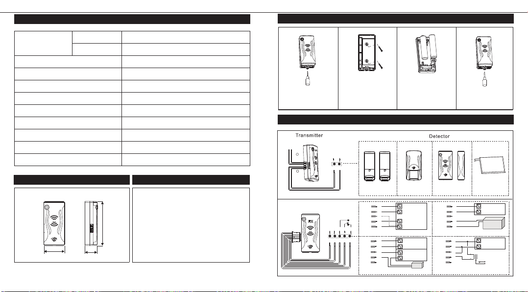
1. SP EC IF IC ATI ON S
Pow er Supp ly
Tempe ratur e
Wor king Fr equen cy
Wir eless D istan ce
Tran smitt er Inp ut
Rec eiver Rela y Outpu t
Bat tery Li fe
Usi ng Envi ronme nts
Pro duct Ce rtifi cates
Tran smitt er
Rec eiver
Dim ensio n
2. DI ME NS IO NS
UNI T:inc h(mm)
2.5
(65.0)
1.2
(31. 0)
*Sp ecifi catio ns and de sign ar e subje ct to
wit hout pr ior not ice.
(18. 5)
0.7
cha nge
x
VAAA LR03
2.5
11
2
12 - 24V DC
- 20 ℃ ~+ 60 ℃
433 .92 MHz
(Op en fiel d)
≥ 100m
Dua l N.O. ( Co ntact w ithou t power )
N. C. /N .O. DC 24 V, 2A Ma x.
3 Years ( Nor mal Mod e)
Ind oor
2.5 "Hx1. 2"Wx0 .7"D( 65.0 x31. 0x1 8.5 mm )
12
FCC C E ROHS
3. SY ST EM PA RI NG
To paring the receiver to the transmitter, required
to trigger the detector(connected with transmitter) in 5 seconds when receiver power on, the
Receiver's LED will flash 6 times when paring
successes.
NOT E:
Every Receiver can only paring one Transmitter,
the previous Transmitter will invalid automatically
when Receiver is success to paring with new one
4. IN STA LL ATI ON
1.
Loos en the bottom s crew and r emov e the
uppe r cov er
2.
Open the l ower cover
mount ing hole and
lock th e screw
5. CO NN EC TI ON M OD E
1
Detector
2
Detector
Can c onnec t two gro ups det ector
*
Rec eiver
N.O. S IGNAL
R B
POWE R
INPU R
V+ V- N.O
R B W P W
ALAR M
COM
3.
+
-
Two batt erie s into th e
Trans mitt er
1
AIR S ensor
V+
_
V
N.O.
COM
N.C.
N.C
ALAR M PANEL CON NECTI ON
V+
_
V
N.O.
COM
N.C.
DOOR S TRIKE C ONNEC TION EXTE RNAL RE LAY CONNE CTION
2 3 4
PIR S ensor
+
R
AUX.
POWE R
-
B
ALAR M PANEL
W
LOOP
P
ALAR M
W
N.C. O R N.O.
R
B
W
P
W
PRDI O
POWE R
XFMA
XFMR
SPWE R
STRI KE
4.
-
+
Insta ll the cover an d
lock th e screw s
Doo r Magne tic
V+
R
_
V
B
N.O.
W
P
COM
N.C.
W
SECU RITY CA MERA CON NECTI ON
V+
R
_
V
B
N.O.
W
COM
P
N.C.
W
Pre ssure
Sen sor Mat
+
POWE R
SUPP LY
-
DVR
PRDI O
POWE R
XFMA
EXTE RNAL
RELAY
LOAD
Page 4

FCC Caution:
Any Changes or modifications not expressly approved by the party responsible for
compliance could void the user's authority to operate the equipment.
This device complies with part 15 of the FCC Rules. Operation is subject to the following
two conditions: (1) This device may not cause harmful interference, and (2) this device
must accept any interference received, including interference that may cause undesired
operation.
 Loading...