


TGP3100 Seri es
Pulse and Universal Generators
QUICK START GUIDE

1 Table of Contents
1 Table of Contents 1
2 Introduction 2
2.1 The TGP3100 Series of Pulse and Universal Generators ....................................................... 2
2.2 About this Guide ..................................................................................................................... 2
3 Safety 3
4 Operational Principles 4
4.1 Front Panel Layout.................................................................................................................. 4
4.2 Rear Panel Layout .................................................................................................................. 5
4.3 Screen Layout ......................................................................................................................... 6
5 Getting Started 7
5.1 Initial Conditions ..................................................................................................................... 7
6 Basic Set-up Examples 8
6.1 Setting-up a Square Wave Clock Signal ................................................................................. 8
6.2 Setting-up a Pulse Waveform ............................................................................................... 11
6.3 Setting-up a Sine Wave Signal ............................................................................................. 15
7 Further Set-up Examples 17
7.1 Setting-up more Output O ptions ........................................................................................... 17
7.2 Setting-up a simple Bit Pattern.............................................................................................. 20
7.3 Setting-up an AM modulated Pulse Waveform ...................................................................... 22
8 Exploring the Generator Capabilities 25
8.1
8.2 PRBS Pattern ....................................................................................................................... 26
8.3 Frequency Modulation of a Pulse Waveform......................................................................... 27
8.4 Pulse Width Modulated Waveform (PWM) ............................................................................ 28
8.5 Pulse Delay Modulated Waveform (PDM) ............................................................................. 29
8.6 Frequency Sweep of a Sine Wave ........................................................................................ 30
8.7 Generating a Triggered Burst ................................................................................................ 31
8.8 Reconstructing an External Pulse Waveform ........................................................................ 32
8.9 Coupling the Frequency of Both Channels (T G P31x2 only) .................................................. 33
8.10 Summing Both Channels Together (TGP31x2 only) .............................................................. 34
9 Maintenance 35
Double Pulse Operation ........................................................................................................ 25
The full Specification for the instrument can be found in the separate Instruction Manual.
Note: The latest revisions of this manual, device drivers and software tools can be
downloaded from: http://www.aimtti.com/support or http://www.aimtti.us/support
This manual is 48591-1340 Issue 1
1
(USA).

2 Introduction
2.1 The TGP3100 Series of Pulse and Universal Generators
2.1.1 General Description
The TGP3100 Series are true pulse gener ators using all digital techniques. They can replicate the
capabilities of traditional pulse generators whilst adding many additional facilities such as pulse
modulations.
As well as operating as pulse generators, the instr um ents can ac t as high performance noise
generators and as function/ ar bit r ary generators - making them truly universal waveform generators.
Single and dual channel models are available with a maximum frequency of either 50MHz or
25MHz
2.1.2 Important Features
Pulse waveforms from 1mHz to 50MHz [25MHz], minimum rise time 5ns [8ns]
Pulse, double pulse, pulse pattern and PRBS waveforms
Pulse period, width, and delay resolutions of 100ps or 11 digits
Independently variable rise and fall times from 5ns [8ns ] t o 800 seconds
Low jitter asynchronous operation, externally triggered pulses or pulse r ec onstruction
High drive capability output can provide 20V pk-pk into 50Ω (unmatched)
Wide rang e of pulse modulations including AM.FM, PM, FSK, BPSK, SUM, PWM, PDM
using internal or external modulation sources.
Triggered (burst count) or g at ed oper ation using internal or external trigger sources
Full Noise generator to 25MHz [12.5MHz] with selectable crest factor and user defined distr ibut ion
Full Arbitrary/Function generator with 16 waveform types
Sine waves up to 50MHz [25MHz]
Arbitrary waveforms at 800MS/s sampling rate and 16-bit vertical r esolut ion
Extensive internal/external modulation of all waveform types
Linear and logarithmic sweeps of all waveform types
Front panel mounted USB Flash drive interface
GPIB, USB and LXI compliant LAN interfaces
2.2 About this Guide
2
This Quick Start guide is for bench-top use of t he TGP3100 Series com prising the TGP3151 and
TGP3121 single channel generators and t he TGP3152 and TGP3122 dual channel generat or s .
A full Instruction Manual (English only) is also provided that includes comprehensive explanations of
all functions and additional information on remote control, calibration, and the detailed technical
specifications.

incorrect operation may damage the instr um ent.
l
3 Safety
This generator is a Safet y Class I instr um ent according to IEC classification and has been desig ned
to meet the requirements of EN61010−1 (Safety Requirements for Elec t r ical Eq uipm ent for
Measurement, Control and Laboratory Use). It is an I nstallation Category II instrument intended f or
operation from a normal single phase supply.
This instrument has been tested in accordanc e with EN61010−1 and has been supplied in a safe
condition. This instruction manual contains some information and warnings which have to be
followed by the user to ensure safe operation and to r etain the inst r um ent in a safe condition.
This instrument has been designed f or indoor use in a Pollution Deg r ee 2 environment in t he
temperature range 5°C to 40°C, 20% − 80% RH (non−condensing). It may occasionally be
subjected to temperatures between +5° and −10°C without degradation of its safet y. Do not
operate while condensation is present.
Use of this instrument in a manner not s pecified by these instructions may impair the safety
protection provided. Do not operate the instrum ent outside its rat ed supply voltages or
environmental range.
WARNING! THIS INSTRUMENT MUST BE EARTHED
Any interruption of the mains earth conduct or inside or outside t he inst r um ent will make the
instrument dangerous. Int entional interruption is prohibited. The protective action must not be
negated by the use of an extension cord without a protective conductor.
When the instrument is connected to its supply, terminals may be live and opening the covers or
removal of parts (except those to which access can be gained by hand) is likely to expose live parts.
The apparatus shall be disconnected from all voltage sources before it is opened for any
adjustment, replacement, m aint enance or repair.
Any adjustment, maintenance and repair of the opened instrument under voltage shall be avoided
as far as possible and, if inevitable, shall be carried out only by a skilled person who is aware of the
hazard involved.
If the instrument is clearly def ec t ive, has been subject to mechanical damage, excessive moisture
or chemical corrosion the safety protec t ion m ay be impaired and the apparatus should be
withdrawn from use and returned for checking and repair.
Make sure that only fuses with the required rated c ur r ent and of the specified type are used for
replacement. The use of makeshift fuses and the short−circuiting of fuse holders is prohibited.
This instrument uses a Lithium button c ell for non−volatile memory battery back−up; typical life is 5
years. In the event of replacement becom ing nec essary, r eplace only with a cell of the cor r ec t t ype,
i.e. 3V Li/Mn0
accordance with local regulations; do not cut open, incinerate, expose to t emperatures above 60°C
or attempt to recharg e.
Do not wet the instrument when cleaning it and in particular use only a soft dry cloth to clean the
LCD window. The f ollowing symbols are used on the inst r ument and in this manual:−
20mm button cell type 2032. Exhausted cells must be disposed of car efully in
2
Caution −refer to t he acc om panying documentation,
terminal connected to chassis ground.
3
mains supply OFF.
mains supply ON.
alternating current.
Ref.
Short Description
Function
the means of disconnection is readily accessible.
Opens Help menu (single channel instruments only).
ARB/Function.)
D
Menus
and Burst
utilities, and trigger conditions.
G
Wheel
Used to select items within some menus.
Main output sockets (dual channel instruments only)
K
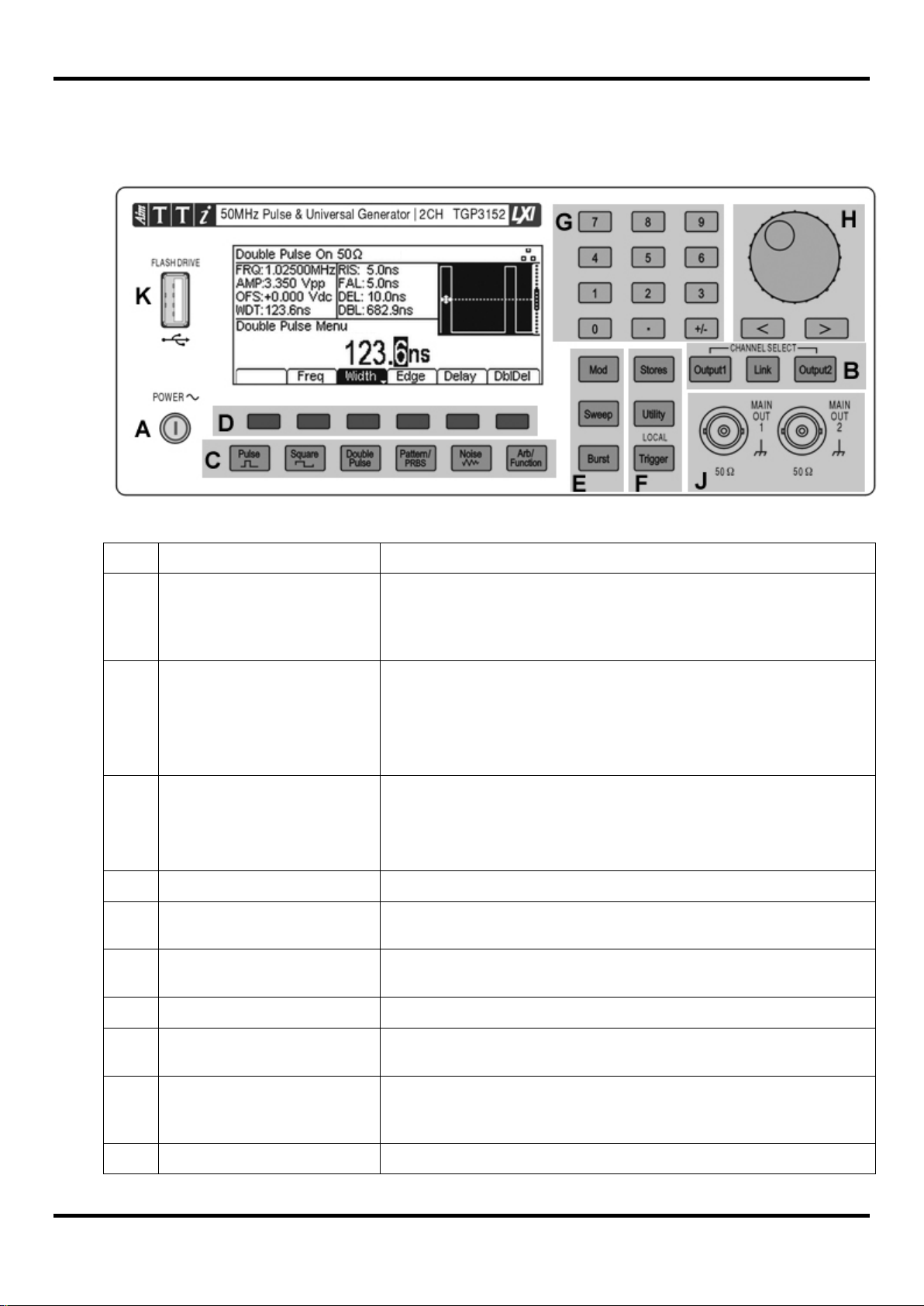
4.1 Front Panel La yout
4 Operational Principles
A
B
C
E
F
Power Switch
Output Menu(s) Select
Channel Select
Help Menu Select
Waveform Menus
Waveform Select
Soft-keys Performs the func t ion shown on the LCD soft-key label above.
Waveform Modification
Other Menus
Numeric Keypad Used to enter numeric parameter values directly.
Switches instrument on or off. Safet y Not e: To fully disconnect
from the AC supply, unplug the m ains cor d from the back of t he
instrument or switch off at the AC supply outlet; make sure that
Opens Output menu(s) to set output parameters
Selects the desired channel for parameter editing ( dual
channel instruments only). Selects Channel Linking menu
(dual channel instruments only).
Opens Waveform menus to set waveform parameters.
Selects the main waveform type (carrier waveform) as active.
(Pulse, Square, Double Pulse, Pattern/PRBS, Noise,
Opens menus for setting parameters for Modulation, Sweep
Selects menus for internal and external file st or age, instrument
H
J
4
Cursor Keys and Spin
Main and/or Sync Sockets
USB Flash Drive USB Host connector for USB Flash drive storage.
Used to change numeric parameter values digit by digit.
Main output and Sync output sockets (single channel
instruments only).
L
Modulation Input
External input for modulation of main waveforms .
10MHz reference clock.
generators.
instruments only).
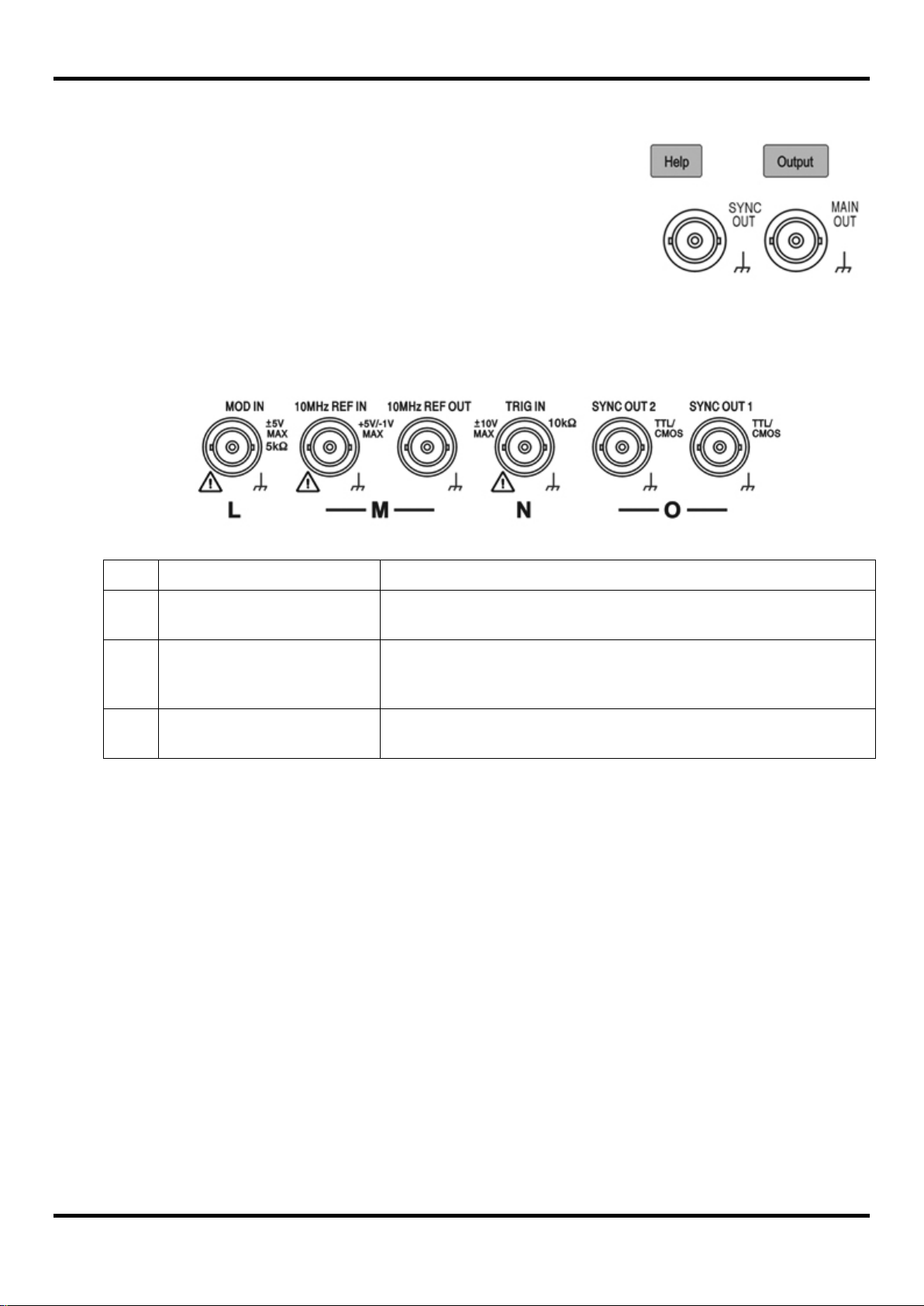
4.1.1 Front Panel Layout - Single Channel Models
On single channel models (TGP31x1) the output terminal area
differs in having only one Output key and Output soc ket.
The Sync output socket is mounted on the front panel instead of the
rear panel.
A Help key is provided that directly accesses the help screens. On
dual channel models Help is accessed from the Utility menu.
4.2 Rear Panel Layout
M
N
O
Reference In/Out
Trigger Input
Sync Outputs
Input for external10MHz reference clock . Output for internal
External input for trigger ing of main waveforms.
Also used with Reference In/Out to synchronise two
Sync signal outputs for both channels (dual channel
5
Ref.
Short Description
Function
only).
Pattern/PRBS, Noise, ARB/Function.).
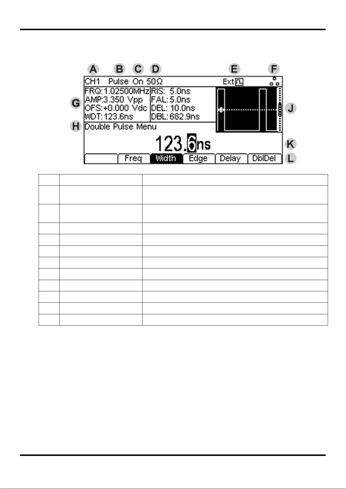
C
D
Load Impedance
Shows load impedance for which output level is displayed.
E
External Clock Indicator
Shows status of external clock (if applied)
F
G
Parameters Box
Shows main parameters for waveform.
H
Menu Description
Shows the currently selected editing menu.
J
K
Edit Box
Shows the current parameter that can be edited
L
Soft-key Labels
Shows the current functions for t he s ix keys below.
4.3 Screen Layout
A
B
Channel Indicator
Main Waveform type
Output State Shows main output On or Off
LAN Status Indicator Shows status of LAN (Ethernet) connection.
Graph Box Shows a graphical representation of the selected waveform.
Shows currently select channel (dual channel instruments
Shows current carrier waveform (Pulse, Square, Double Pulse,
6

5 Getting Started
In order to familiarise the user with some of the basic functionalities of the instrument, a number of
set-up examples are shown in this guide.
It is recommended that all users should carr y out t he first three examples:
• Setting up a square wave clock signal
• Setting up a pulse signal
• Setting up a sine wave signal
This will have introduced some of the basic operating principles. These can be expanded in the
next three examples:
• Setting-up more Output O ptions
• Setting-up a simple Bit Pattern
• Setting-up an AM modulated Pulse Waveform
A number of further set-up examples are provided that assume some familiarity with the instrument:
• Double Pulse Operation
• PRBS Pattern
• Frequency Modulation of a Pulse Waveform
• Pulse Width Modulated Waveform ( PWM)
• Pulse Delay Modulated Waveform (PDM)
• Frequency Sweep of a Sine Wave
• Generating a Triggered Burst
• Reconstructing an External Pulse Waveform
• Coupling the Frequency of Both Channels (TG P31x2 models only)
• Summing Both Channels Together (TGP31x2 models only)
For more detailed information on all functionality - see the full Instruction Manual.
5.1 Initial Condi tions
Before setting up the instr um ent for any of the examples, it should be returned to default conditions.
To do this f ollow these steps:
Press the hard key marked Utility
Press the soft-key labelled System
Press the soft-key labelled Default (display will show Restore Factory Default?)
Press the soft-key labelled Yes
This sets the main waveform to Pulse (10kHz, 50% duty cycle, 1V pk -pk) and cancels any
modulations, sweep, or burst trigg ering or gating.
NOTE:
The instrument can be set to remember its latest settings on power-off and r estore them at poweron. This is set from the Utility menu and the PwrOn soft-key. This setting will be lost when the
instrument is restored to default conditions as described above.
7
6 Basic Set-up Examples
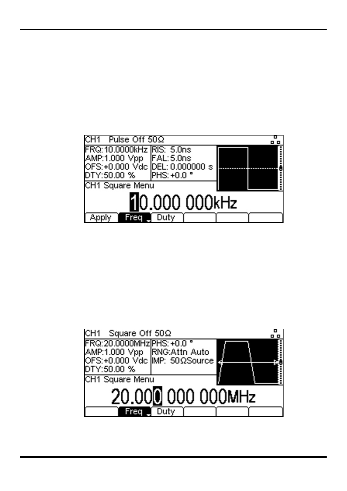
6.1 Setting-up a Square Wave Clock Signal
Requirement
Output a continuous square wave clock signal with 20MHz frequency, 50% duty cycle and a high
level of 3.3V and a low level of 0.0 volts.
Starting Conditions
Before starting, reset t he inst rument to defaults as described in section 5.1 Initial Conditions
Open Waveform Menu - Square
• Press the hard key marked Square, followed by the soft-key labelled Apply.
Note that the new waveform t y pe does not bec om e active until the Apply key is pressed.
Set the Frequency
• Press the soft-key labelled Freq - the current frequency appears in the edit box.
Note that pressing this soft-key repeatedly changes its funct ion bet w een Frequency and Period.
.
• Use the numeric keypad to enter a new frequency. Press the numbers 2 0.
Note that, as soon as a number is entered, t he soft-keys change to show units of frequency.
• Press the soft-key labelled MHz to confirm a frequency of 20MHz.
Note that the graph box changes to show t he r ise t im e on t he edges which is now significant.
Confirm the Duty Cycle
• Press the soft-key labelled Duty - the curr ent duty cycle appears in the edit box.
Note that the duty cycle is already set at 50% , but c ould be changed her e if r equired.
8
Open the Output Menu
• Press the hard key marked Output (or Output1 on dual channel instruments)
- the current pk-pk amplitude appears in the edit box.
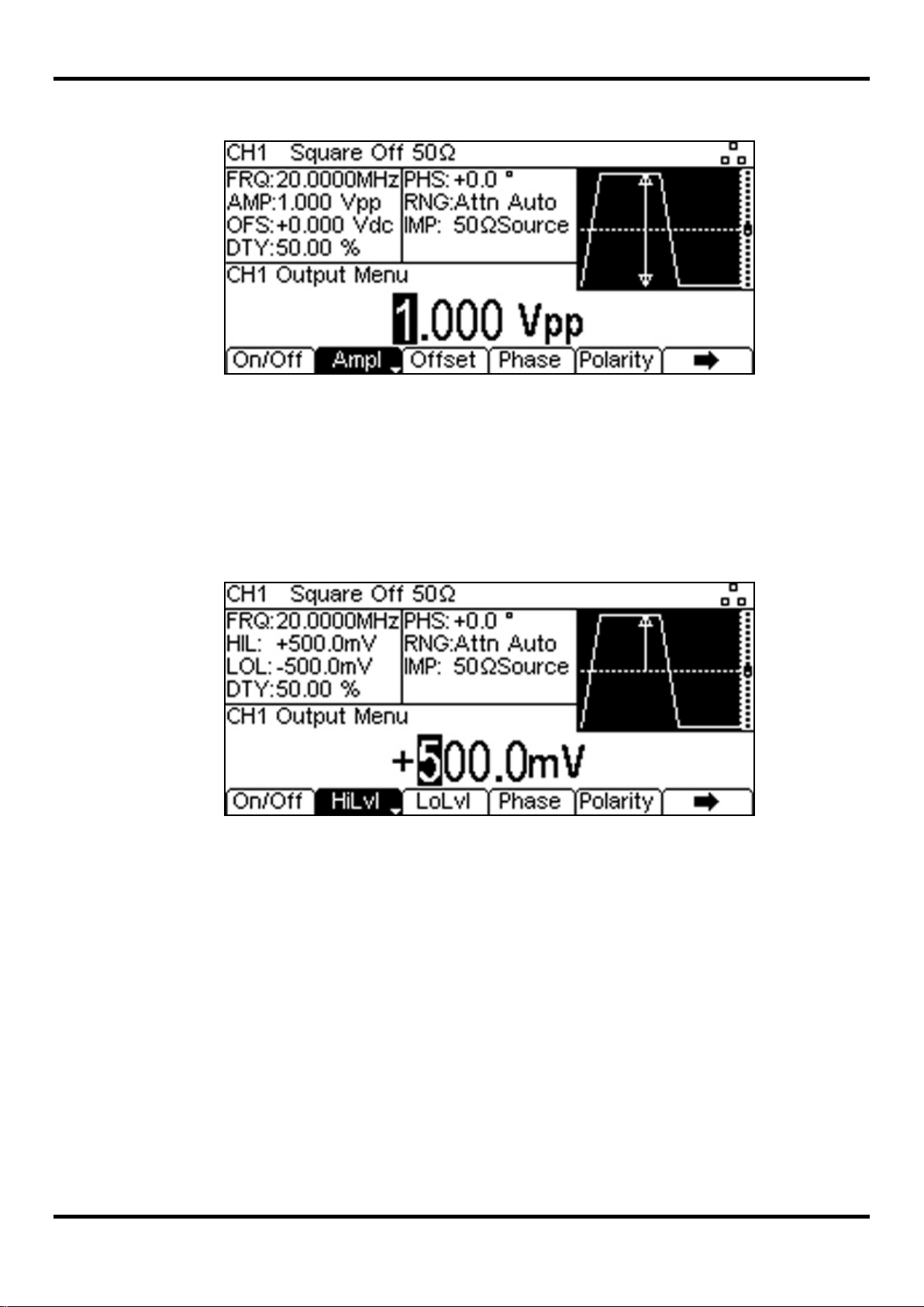
Set the High and Low Levels
• Press the soft-key labelled Ampl - the k ey label changes to HiLvl and the current high level
voltage appears in the edit box
Note that successive presses of the Ampl soft-key changes the Ampl and Offset key labels to
HiLvl (high level) and LoLvl (low level) and vice versa.
• Press the soft-key labelled HiLvl - the cur r ent high level voltage appears in the edit box.
• Use the numeric keypad to enter a new level. Press the numbers 3 . 3 .
Note that, as soon as a number is entered, t he soft-keys change t o s how units of voltage.
• Press the soft-key labelled V to confirm a high level of 3.3 volts.
• Press the soft-key labelled LoLvl - the c ur r ent low level voltage appears in the edit box.
• Use the numeric keypad to enter a new level. Press 0 .
• Press the soft-key labelled V to confirm a low level of 0.0 volts.
Turn t he O ut put On
• Press the soft-key labelled On/Off to set the main output to On.
Note that the Output key illuminates in green t o indicat e t he on s tate.
9
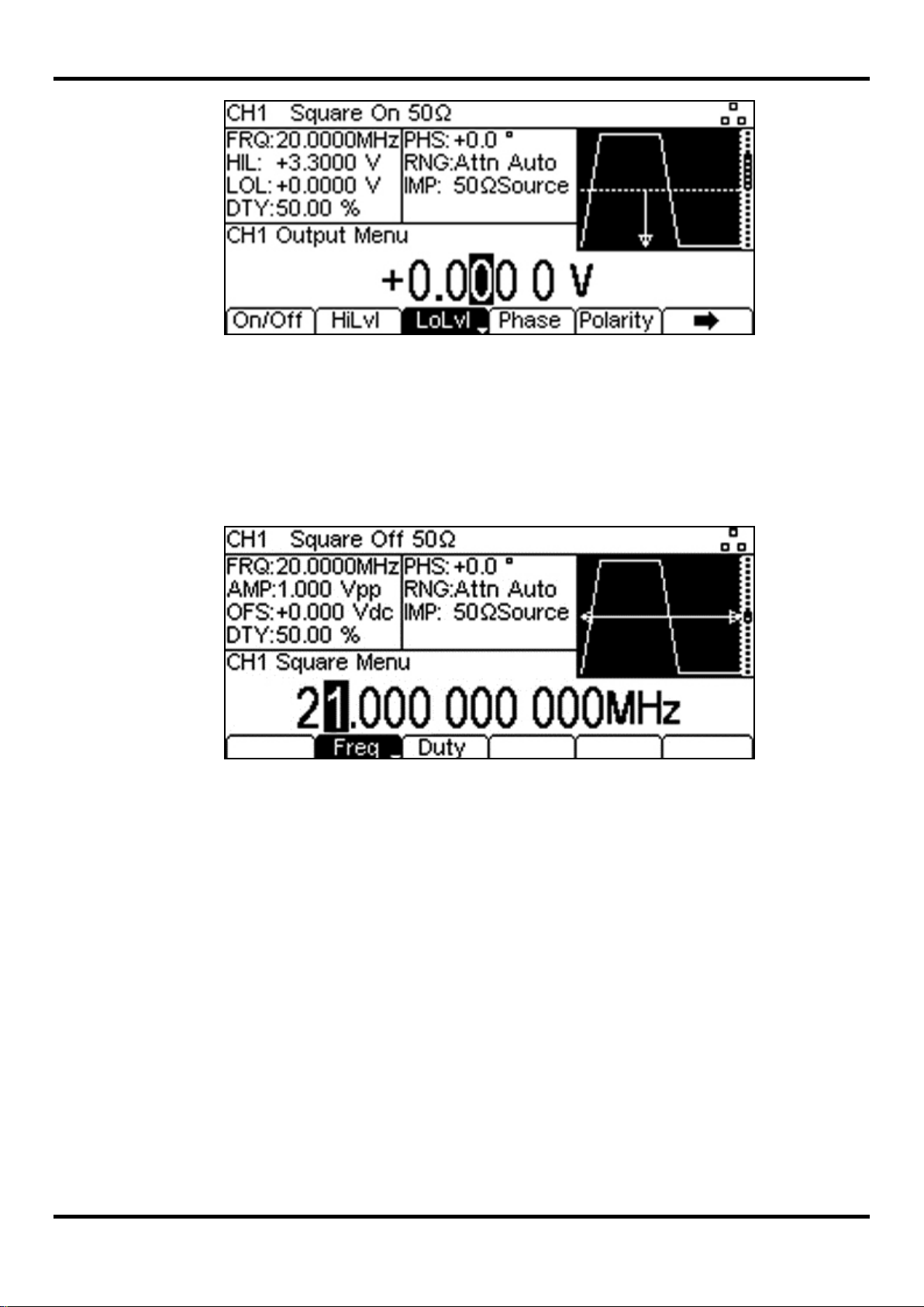
To make f urther changes to Frequency or Duty Cycle
• Press the hard key marked Square.
This closes the output menu and opens the wavefor m m enu.
Making live changes to any numeric parameter (e.g. Frequency)
Numeric parameters can be changed by using the cursor keys and spin w heel as an alt er native to
the numeric keypad.
• Press the hard key marked Square.
• Press the soft-key labelled Freq – t he cur rent frequency value of 20.0MHz is displayed
• Press the Cursor hard keys to move the edit highlig ht to the second digit.
• Use the spin wheel to change the value – the frequency is changed immediately.
NOTE:
Soft-key labels that include a downward arrow perform mor e t han one a function when pressed.
This may be a change in parameter type or parameter option.
10
6.2 Setting-up a Pul se Waveform
Requirement
Output a continuous pulse signal with 100ns period, 30ns pulse width, zero delay, 10ns edge times
and a high level of 2.7V and a low level of -0.6 volts.
Starting Conditions
Before starting, reset t he inst rument to defaults as described in section 5.1 Initial Conditions
Open Waveform Menu - Pulse
Note that the Pulse waveform menu w ill be already select ed as t he def ault.
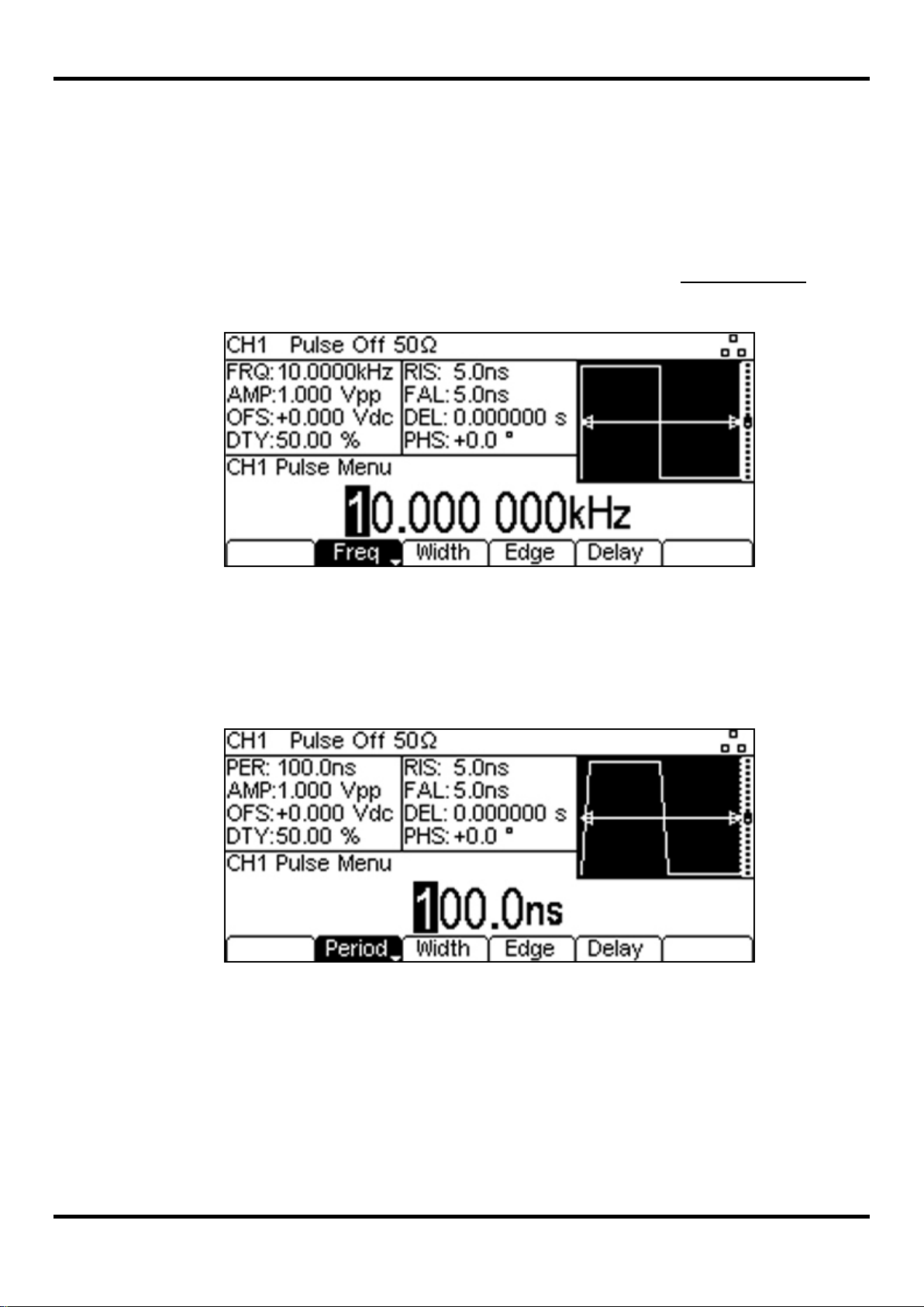
Set the Period
• Press the soft-key labelled Freq so t hat it changes to Period - the current period appears in
the edit box.
Note that pressing this soft-key repeatedly changes its funct ion bet w een Frequency and Period.
.
• Use the numeric keypad to enter a new period. Press the numbers 1 0 0.
Note that, as soon as a number is entered, t he soft-keys change t o s how units of t im e.
• Press the soft-key labelled ns to confirm a period of 100ns.
Note that the graph box changes to show a representation of the pulse and edge times.
11

Set the Pulse Width
• Press the soft-key labelled Width t o open the pulse width sub-menu.
Note that by default the pulse width is described in terms of duty cycle.
• Press the soft-key labelled Width t o display the width as a time.
• Use the numeric keypad to enter a new width. Press the numbers 3 0.
Note that, as soon as a number is entered, t he soft-keys change t o s how units of t im e.
• Press the soft-key labelled ns to confirm a width of 30ns.
• Press the soft-key labelled Done to ret urn to the main pulse menu.
Set the Pulse Edge Times
• Press the soft-key labelled Edge to open the pulse edge sub-menu.
Note that by default the edge times are set together (coupled) but that Mode key can be used to
choose independent rise and fall times when required.
Note that edge times can be set as an absolute t ime or as a per centage of t he pulse width.
Pressing the Edge soft-key repeatedly changes its function between t ime and per c entage.
12
• Use the cursor keys to select the dig it r epr es ent ing units of 1ns
• Use the spin wheel to change the value to 10.0ns
• Press the soft-key labelled Done to ret urn to the main pulse menu.
Note that the value could have been entered using the numeric keypad if pref erred.

Confirm the Pulse Delay
• Press the soft-key labelled Delay - the current pulse delay appears in the edit box.
Note that the delay is already set to zero, but could be changed here if required.
Open the Output Menu
• Press the hard key marked Output (or Output1 on dual channel instruments)
- the current pk-pk amplitude appears in the edit box.
13

Set the High and Low Levels
• Press the soft-key labelled Ampl - the k ey label changes to HiLvl and the current high level
voltage appears in the edit box
Note that successive presses of the Ampl soft-key changes the Ampl and Offset key labels to
HiLvl (high level) and LoLvl (low level) and vice versa.
• Press the soft-key labelled HiLvl - the cur r ent high level voltage appears in the edit box.
• Use the numeric keypad to enter a new level. Press the numbers 2 . 7 .
Note that, as soon as a number is entered, t he soft-keys change t o s how units of voltage.
• Press the soft-key labelled V to confirm a high level of 2.7 volts.
• Press the soft-key labelled LoLvl - the c ur r ent low level voltage appears in the edit box.
• Use the numeric keypad to enter a new level. Press - . 6 .
• Press the soft-key labelled V to confirm a low level of -600 mV.
Turn t he O ut put On
• Press the soft-key labelled On/Off to set the main output to On.
Note that the Output key illuminates in green t o indicate the on state.
14
To make f urther changes to the pulse waveform
• Press the hard key marked Pulse.
This closes the output menu and opens the wavefor m m enu.
NOTE:
Soft-key labels that include a downward arrow perform mor e t han one a function when pressed.
This may be a change in parameter type or parameter option.

6.3 Setting-up a Si ne Wave Signal
Requirement
Output a continuous sine wave signal with 15MHz frequency and an amplitude of 6 volts pk-pk.
Starting Conditions
Before starting, reset t he inst rument to defaults as described in section 5.1 Initial Conditions
Open Waveform Menu - Arb/Function
• Press the hard key marked Arb/Function, f ollowed by the soft-key labelled Apply.
Note that the new waveform t y pe does not bec om e active until the Apply key is pressed.
Set the Frequency
• Press the soft-key labelled Freq - the current frequenc y appears in the edit box.
Note that pressing this soft-key repeatedly changes its funct ion between Frequency and Period.
.
• Use the numeric keypad to enter a new frequency. Press the numbers 1 5.
Note that, as soon as a number is entered, t he soft-keys change t o s how units of f r equenc y.
• Press the soft-key labelled MHz to confirm a frequency of 15MHz.
15

Confirm the Waveform Type
• Press the soft-key labelled Waves - the soft-keys change to show alternative waveforms.
Note that the waveform t ype is already set to sine, but could be changed here if required.
Open the Output Menu
• Press the hard key marked Output (or Output1 on dual channel instrum ents)
- the current pk-pk amplitude appears in the edit box.
Set the Amplitude
Note that successive presses of the Ampl soft-key changes the Ampl and Offset key labels to
HiLvl (high level) and LoLvl (low level) and vice versa.
• Use the numeric keypad to enter a new amplitude. Press the number 6 .
Note that, as soon as a number is entered, t he soft-keys change t o s how units of voltage.
• Press the soft-key labelled V to confirm a pk-pk amplitude of 6.0 volts.
Turn t he O ut put On
• Press the soft-key labelled On/Off to set the main output to On.
Note that the Output key illuminates in green t o indicate the on state.
To make f urther changes to Waveform or Frequency
• Press the hard key marked Arb/Function.
This closes the output menu and opens the wavef or m m enu.
NOTE:
Soft-key labels that include a downward arrow perform mor e t han one a function when pressed.
This may be a change in parameter type or parameter option.
16

7 Further Set-up Examples
In the following examples it is assumed that the user has under s t ood the basic operation of the
instrument from t he pr evious set-up examples.
7.1 Setting-up more Output Options
Requirement
In the earlier set-up examples it was shown how the output menu is used to set the output level
(amplitude plus offset or high level plus low level) and turn the output on or off. This example
demonstrates the setting of output phase, output polarity, source impedance and load impedance.
Starting Conditions
Before starting, reset t he inst rument to defaults as described in section 5.1 Initial Conditions
Open the Output Menu
• Press the hard key marked Output (or Output1 on dual channel instruments)
- the current pk-pk amplitude appears in the edit box.
Set the Amplitude
• Enter a pk-pk amplitude of 11.0 volts with an offset of zero.
Note that this is the largest amplitude that can be s et with a source impedance and load impedance
both at 50 Ohms.
.
17

Change the Output Phase
• Press the soft-key labelled Phase to open the output phase sub-menu
• Enter a phase of -45 degree.
• Press the soft-key labelled Done to ret urn to the main output menu.
The set phase angle is the point in the wavef or m per iod w hich is coincident with the Sync or trigger
edge, i.e. it is the point in the period at which the waveform starts. Hence a negative phase setting
advances, and a positive phase setting delays the wavefor m relative to the Sync or trigger; the
waveform in the graph box changes to show this.
Note that Phase is not the same as Delay. Phase is a defined proportion of the period whereas
pulse Delay is a defined time.
The phase can be returned to zero by pressing the Reset soft-key. The Align soft-key appears only
on two channel generators and is used to re-align phase when making frequency changes.
Change the Output Polarity
• Press the soft-key labelled Polarity to invert the output polarity.
Note that successive presses of the Polarity k ey alt er nates between normal and inverted.
18

Change the Load Impedance
• Press the soft-key labelled
Note that the default load impedance is 50 Ohms, but that this could be changed to any impedance
between 50 and 10,000 Ohms. Levels are calculated based upon t his im pedance.
• Press the soft-key labelled Load to change the load impedance to High-z (high impedance).
to move to the next set of menu options.
Successive presses of the Load key alternates bet w een a num eric value and High-z.
Note that the amplitude readout increases t o 22 volts pk-pk.
• Press the soft-key labelled Load to return the load impedance to 50 Ohms.
Change the Source Impedance
• Press the soft-key labelled Source to set the generator output impedance t o 5 Ohms.
Successive presses of the Source key alternates between a 50 Ohms and 5 Ohms.
Note that the amplitude readout increases t o 20 volts pk-pk.
19

7.2 Setting-up a simple Bit Pattern
Requirement
Create a user-defined continuously repeating bit patt er n of 8 bits at 25MBps.
Starting Conditions
Before starting, reset t he inst rument to defaults as described in section 5.1 Initial Conditions
Open the Pattern/PRBS Menu
• Press the hard key marked Pattern/PRBS to open the pattern waveform menu.
Note that the default pattern source is an inter nal PRBS (pseudo random bit s t r eam).
Select a Pattern to Use
• Press the soft-key labelled Source to select one of four patterns available.
.
• Press the soft-key labelled Pttn1 (or any unused pattern) to select t he patt er n.
• Press the soft-key labelled Done to ret ur n t o the main menu.
20

Set the Bit Rate
• Press the soft-key labelled BitRate and enter 25Mbps as the bit rate.
Edit the Pattern
• Press the soft-key labelled EditPttn.
• Press the soft-key labelled Edit to enter the pattern editing menu.
• Press the soft-key labelled Length and change the pattern length to 8.
As supplied from the factory, all patterns are 4 bits long. This can be increased to any number up to
65536 bits.
• Press the soft-key labelled Point t o enter the point edit sub-menu.
• Edit the points using the Point# soft-key to select the point position number, and the High
and Low soft-keys to set the bits as high or low.
• Press the
• Press the soft-key labelled Done to ret urn to the main Pattern/PRBS waveform menu.
The newly defined 8 bit pattern is now active.
21
key to return to the previous menu.

7.3 Setting-up an AM modulated Pulse Waveform
Requirement
Create a 10MHz pulse waveform amplitude modulated by a 100kHz sine wave signal.
Starting Conditions
Before starting, reset t he instrument to defaults as described in section 5.1 Initial Conditions
Set the Main Waveform Frequency
• Set a pulse repetition frequency of 10MHz.
Note that the carrier wavefor m is set to pulse by default.
Open the Modulation Menu
• Press the hard key marked Mod to open the modulation menu.
Note that the default modulation type is AM.
.
Set the Modulation Frequency
• Press the soft-key labelled Freq and set t he m odulat ion frequency to 100kHz.
Set the Modulation Depth
• Press the soft-key labelled Depth and set the modulation depth to 100%.
Turn M odul at ion On
• Press the soft-key labelled On/Off to turn t he m ain out put to on.
Note that the hard key marked Mod illuminates and the display changes to show modulation
parameters and a graphical representation of the modulation.
22

• Press the Source and Shape soft-keys in turn t o c onfirm the settings as inter nal m odulation
source and sine wave shape.
Note that these are the default settings.
The resultant output can be observed on an oscilloscope:
Change the Modulation to AM-SC
• Press the soft-key labelled Type and change the modulation t ype to AM-SC (suppressed
carrier amplitude modulation.
23

The change can be seen on the oscilloscope:
Alternative modulation types and modulation wave shapes could be selected.
See the full Instruction Manual for detailed explanations.
24

MENU
HARD KEY NA ME
Double Pulse
Double Pulse
Parameter
Soft-key Name
Setting
Period
(Freq) Period
250ns
Width
(Duty) Width
50ns
Edge Mode
Edge > Mode
Independent
Rise
Fall Time
Fall
20ns
Delay
Delay
0ns
DblDel
MENU
HARD KEY NA ME
Output
Output
Parameter
Soft-key Name
Setting
Ampl
Offset
Offset
0.0V
Output State
On/Off
On
8 Exploring the Generator Capabilities
In the following examples only the parameter settings ar e desc r ibed, t ogether with the related key
names. The resultant output waveforms are shown, along with the sync or trig ger waveform where
relevant. Output amplitude and offset settings are examples only and need not be followed.
8.1 Double Pulse Operation
Start with the instrument returned to Default Setting s.
Rise Time
Double Delay
Amplitude
10ns
160ns
5.0V
25

MENU
HARD KEY NA ME
Pattern/PRBS
Pattern/PRBS
Parameter
Soft-key Name
Setting
Bit Rate
BitRate
1Mbps
Edge Time
Edge
250ns
Source
Source
PRBS
Type
MENU
HARD KEY NA ME
Output
Output
Parameter
Soft-key Name
Setting
Amplitude
Ampl
3.3V
Offset
Offset
1.65V
Output State
On/Off
On
8.2 PRBS Pattern
Start with the instrument returned to Default Settings.
PRBS Type
PN7
26

MENU
HARD KEY NA ME
Modulation
Mod
Parameter
Soft-key Name
Setting
Modulation State
On/Off
On
Modulation Type
Type
FM
Modulation Frequency
Freq
1kHz
Deviatn
MENU
HARD KEY NA ME
Output
Output
Parameter
Soft-key Name
Setting
Amplitude
Ampl
1.0V
Offset
Offset
0.0V
Output State
On/Off
On
8.3 Frequency Modulation of a Pulse Waveform
Start with the instrument returned to Default Settings.
Deviation
9kHz
Note that the frequenc y/period is m odulat ed but the pulse width remains constant.
27

MENU
HARD KEY NA ME
Modulation
Mod
Parameter
Soft-key Name
Setting
Modulation State
On/Off
On
Modulation Type
Type
PWM
Modulation Frequency
Freq
1kHz
Deviatn
MENU
HARD KEY NA ME
Output
Output
Parameter
Soft-key Name
Setting
Amplitude
Ampl
1.0V
Offset
Offset
0.0V
Output State
On/Off
On
8.4 Pulse Width Modulated Waveform (PWM)
Start with the instrument returned to Default Settings.
Deviation
20us
28

MENU
HARD KEY NA ME
Pulse
Pulse
Parameter
Soft-key Name
Setting
Delay
Delay
25us
MENU
HARD KEY NA ME
Modulation
Mod
Parameter
Soft-key Name
Setting
Modulation State
On/Off
On
Modulation Type
Type
PDM
Freq
Deviation
Deviatn
10us
MENU
HARD KEY NA ME
Output
Parameter
Soft-key Name
Setting
Amplitude
Ampl
1.0V
Offset
Offset
0.0V
On/Off
8.5 Pulse Dela y Modulated Waveform (PDM)
Start with the instrument returned to Default Settings.
Modulation Frequency
Output
Output State
1kHz
On
29

MENU
HARD KEY NA ME
Arb/Function
Arb/Function
Parameter
Soft-key Name
Setting
Waveform
Waves
Sine
MENU
HARD KEY NA ME
Sweep
Sweep
Parameter
Soft-key Name
Setting
Sweep State
On/Off
On
MENU
HARD KEY NA ME
Output
Parameter
Soft-key Name
Setting
Amplitude
Ampl
1.0V
Offset
Output State
On/Off
On
8.6 Frequency Sweep of a Sine Wave
Start with the instrument returned to Default Settings.
Output
Offset
0.0V
30

MENU
HARD KEY NA ME
Pulse
Pulse
Parameter
Soft-key Name
Setting
Frequency
Freq
6MHz
MENU
HARD KEY NA ME
Burst
Burst
Parameter
Soft-key Name
Setting
Burst State
On/Off
On
Burst Count
Count
3
SetTrg > Source > Ext
MENU
HARD KEY NA ME
Output
Output
Parameter
Soft-key Name
Setting
Amplitude
Ampl
1.0V
Offset
Offset
0.0V
Output State
On/Off
On
8.7 Generati ng a Tri ggered Burst
Start with the instrument returned to Default Settings.
Trigger Source
Connect an external 1MHz square wave trigger signal of +3V /-0V level to the TRIG IN input.
Note that, on a two channel generator, the second channel could be selected in place of the
external trigger signal.
External Trigger
Note that the second trace is the output f rom the Sync Out socket which follow s t he trigger input
signal. Both the main and sync outputs are delayed by 448ns relative to t he t r igger input .
31

MENU
HARD KEY NA ME
Trigger
Trigger
Parameter
Soft-key Name
Setting
External Width
ExtWdt > Yes
Yes
MENU
HARD KEY NA ME
Pattern/PRBS
(Pattern/PRBS)
Parameter
Soft-key Name
Setting
Edge
MENU
HARD KEY NA ME
Output
Output
Parameter
Soft-key Name
Setting
Amplitude
Ampl
5.0V
Offset
Offset
0.0V
Output State
On/Off
On
8.8 Reconstructing an External Pulse Waveform
Note that this mode of operation is refer red to as External Width. It is a variant of the Pattern
waveform but can be accessed from the Trigger menu.
Start with the instrument returned to Default Settings.
Edge Speed
Connect an external 10MHz square wave trigger signal of +2V /-0V level to the TRIG IN input.
20ns
The waveform is recreated with a different amplitude and offset and a defined edge speed.
Note that a fixed delay of 448ns between output and t r igger is intr oduc ed.
Note that AM or SUM modulations could be performed on the reconstructed waveform, if required.
32

MENU
HARD KEY NA ME
Link
Parameter
Soft-key Name
Setting
Frequencies
Freq > On/Off
Coupled
Coupling Ratio
Ratio
(1.000)
MENU
HARD KEY NA ME
Output 1
Output1
Parameter
Soft-key Name
Setting
On/Off
MENU
HARD KEY NA ME
Output 2
Output2
Parameter
Soft-key Name
Setting
Phase Shift
Phase
90 degrees
Output State
On/Off
On
MENU
HARD KEY NA ME
Pulse
Parameter
Soft-key Name
Setting
Frequency
Freq
1MHz
8.9 Coupling the Frequency of Both Channels (TGP31x2 only)
Note that the following applies only to two channel generators.
Start with the instrument returned to Default Settings.
Channel Linking
Output State
Pulse
On
Note that, when channel 2 is set to 1MHz, channel 2 is also set to 1MHz.
The 90 degree phase shift between the channels can be seen.
33

MENU
HARD KEY NA ME
Output 1
Output1
Parameter
Soft-key Name
Setting
Output State
On/Off
On
MENU
HARD KEY NA ME
Pulse
Pulse
Parameter
Soft-key Name
Setting
Freq
MENU
HARD KEY NAME
Burst
Burst
Parameter
Soft-key Name
Setting
Burst State
On/Off
On
Burst Count
Count
10
Trigger Source
SetTrg > Source > Int
Internal Trigger
Period
MENU
HARD KEY NA ME
Output 2
Output2
Parameter
Soft-key Name
Setting
Output State
On/Off
On
MENU
HARD KEY NA ME
Arb/Function
Arb/Function
Parameter
Soft-key Name
Setting
Waveform Type
Waves
Sine
Frequency
Freq
1kHz
MENU
HARD KEY NA ME
Modulation
Mod
Parameter
Soft-key Name
Setting
Type > SUM
Summing Level
Level
100%
Modulation Source
Source > Chn2
Channel 2
Modulation State
On/Off
On
8.10 Summing Both Channels Together ( TGP31x2 only)
Note that the following applies only to two channel generators.
Start with the instrument returned to Default Settings.
Frequency
Trigger Period
100kHz
1ms
Modulation Type
34
SUM

Note that the channel 2 signal is summed onto the channel 1 signal (upper trace) while the
channel 1 signal (lower trace) remain unchanged.
9 Maintenance
The Manufacturers or their ag ents overseas will provide a repair service for any unit developing a
fault. Where owners wish to undertake their own maintenance work, this should only be done by
skilled personnel in conjunction with the service guide which may be obtained directly from the
Manufacturers or their agents overseas.
9.1.1 Cleaning
If the instrument r equires cleaning use a cloth that is only lightly dampened with water or a mild
detergent.
WA RNING! TO AVOID ELECTRIC SHOCK, OR DAMAGE TO THE INSTRUMENT, NEVER
ALLOW WATER TO GET INSIDE THE CASE. TO AVOID DAMAGE TO THE CASE NEVER
CLEAN WITH SOLVENTS.
35

Aim Instruments an
Thurlby Thandar Instruments
Ltd
.
Glebe Road • Huntingdon • Cambridgeshire • PE29 7DR • England (United Kingdom
Telephone: +44 (0)1480 412451 • Fax: +44 (0)1480 450409
International web site:
www
.aimtti.com • UK web site:
www
.aimtti.co.uk
Email: info@aimtti.com
d Thurlby Thandar Instruments
)
 Loading...