

Page 1

INSTRUCTION MANUAL
EN
TGF4000 SERIES
40MHz, 80MHz, 160MHz & 240MHz
Dual Channel Arbitrary Funcon Generators
Page 2

Overview
1.
1. CONTENTS .................................................................................................................................................... 1
2. Introduction ................................................................................................................................................... 7
Overview ....................................................................................................................................................................... 7
3. Safety ............................................................................................................................................................. 8
Symbols ........................................................................................................................................................................ 8
Safety notices ................................................................................................................................................................ 9
4. Installation ..................................................................................................................................................... 10
Mounting ..................................................................................................................................................................... 10
Ventilation.................................................................................................................................................................... 10
Handle/stand ............................................................................................................................................................... 10
5. Electrical Requirements ............................................................................................................................... 11
Mains operating voltage .............................................................................................................................................. 11
Mains lead ................................................................................................................................................................... 11
6. Front Panel .................................................................................................................................................... 12
Overview ..................................................................................................................................................................... 12
7. Rear Panel ..................................................................................................................................................... 14
Connections overview ................................................................................................................................................. 14
8. Getting Started .............................................................................................................................................. 16
Using this manual ........................................................................................................................................................ 16
Switching on ................................................................................................................................................................ 16
Screen layout .............................................................................................................................................................. 17
Status line details ........................................................................................................................................................ 18
Display options ............................................................................................................................................................ 19
Numeric editing ........................................................................................................................................................... 20
Editing principles ......................................................................................................................................................... 22
Information, warning and error messages ................................................................................................................... 23
1 TGF4000 Series Instruction Manual
Page 3

Overview
General soft-keys ........................................................................................................................................................ 24
Maintenance ................................................................................................................................................................ 24
Cleaning ...................................................................................................................................................................... 24
9. Continuous Carrier Waveform Operation ................................................................................................... 25
Waveform selection ..................................................................................................................................................... 25
Waveform editing ........................................................................................................................................................ 26
Square-wave duty cycle .............................................................................................................................................. 28
Ramp symmetry .......................................................................................................................................................... 29
Output ......................................................................................................................................................................... 30
Arb waves ................................................................................................................................................................... 33
Arb arbs....................................................................................................................................................................... 35
Sync output ................................................................................................................................................................. 39
10. Pulse Generator ........................................................................................................................................ 40
Pulse application ......................................................................................................................................................... 40
Pulse width .................................................................................................................................................................. 41
Edge times .................................................................................................................................................................. 42
Pulse delay.................................................................................................................................................................. 43
11. Noise Generator ........................................................................................................................................ 44
Carrier wave noise ...................................................................................................................................................... 44
Noise modulation ........................................................................................................................................................ 45
12. PRBS Generator ........................................................................................................................................ 46
Carrier wave PRBS ..................................................................................................................................................... 46
PRBS modulation ........................................................................................................................................................ 47
13. Modulation ................................................................................................................................................. 48
Modulation application ................................................................................................................................................ 48
Amplitude modulation (AM) ......................................................................................................................................... 50
Frequency modulation (FM) ........................................................................................................................................ 54
Phase modulation (PM) ............................................................................................................................................... 58
Amplitude shift keying (ASK) ....................................................................................................................................... 62
2 TGF4000 Series Instruction Manual
Page 4

Overview
Frequency shift keying (FSK) ...................................................................................................................................... 66
Binary phase shift keying (BPSK) ............................................................................................................................... 70
SUM modulation .......................................................................................................................................................... 74
Pulse width modulation (PWM) ................................................................................................................................... 78
14. Sweep ......................................................................................................................................................... 82
Sweep application ....................................................................................................................................................... 82
Sweep type ................................................................................................................................................................. 84
Sweep time ................................................................................................................................................................. 87
Sweep mode ............................................................................................................................................................... 87
15. Burst ........................................................................................................................................................... 91
Overview ..................................................................................................................................................................... 91
Burst application .......................................................................................................................................................... 92
Burst type .................................................................................................................................................................... 93
Burst count .................................................................................................................................................................. 94
Burst phase ................................................................................................................................................................. 95
Burst triggering ............................................................................................................................................................ 96
16. Dual Channel Operation ........................................................................................................................... 99
Channel selection ........................................................................................................................................................ 99
Linked channels ........................................................................................................................................................ 100
Coupled operation ..................................................................................................................................................... 101
Tracking options ........................................................................................................................................................ 103
17. External Counter ....................................................................................................................................... 105
Counter menu ........................................................................................................................................................... 105
Counter source .......................................................................................................................................................... 106
Counter type .............................................................................................................................................................. 107
Measurement ............................................................................................................................................................ 107
18. Harmonic Waveforms ............................................................................................................................... 108
Selecting arb location to store harmonic waveforms ................................................................................................. 108
Editing harmonic waveforms ..................................................................................................................................... 110
3 TGF4000 Series Instruction Manual
Page 5

Overview
19. Utility Menu ................................................................................................................................................ 113
System ...................................................................................................................................................................... 113
Instrument settings .................................................................................................................................................... 118
I/O ............................................................................................................................................................................. 120
Calibration ................................................................................................................................................................. 120
Dual channel operation ............................................................................................................................................. 120
Help ........................................................................................................................................................................... 120
20. Stores Menu .............................................................................................................................................. 121
Flash drive files and folders....................................................................................................................................... 121
Using the stores menu .............................................................................................................................................. 122
Operations on set-up files ......................................................................................................................................... 124
Operations on waveform files .................................................................................................................................... 129
21. Help Operations ........................................................................................................................................ 133
Help menu ................................................................................................................................................................. 133
Help topics ................................................................................................................................................................ 134
22. Editing Arbitrary Waveforms ................................................................................................................... 135
Selecting an arbitrary waveform for editing ............................................................................................................... 135
Editing an arbitrary waveform .................................................................................................................................... 136
23. Calibration ................................................................................................................................................. 141
Equipment required ................................................................................................................................................... 141
Calibration procedure ................................................................................................................................................ 141
Password control ....................................................................................................................................................... 142
Calibration routine ..................................................................................................................................................... 144
Remote calibration .................................................................................................................................................... 146
24. Remote operation ..................................................................................................................................... 147
Overview ................................................................................................................................................................... 147
Address selection ...................................................................................................................................................... 148
Remote/ local operation ............................................................................................................................................ 149
4 TGF4000 Series Instruction Manual
Page 6

Overview
USB interface ............................................................................................................................................................ 149
Installing USB driver for the first time ........................................................................................................................ 150
LAN interface ............................................................................................................................................................ 151
LAN connection ......................................................................................................................................................... 151
GPIB interface ........................................................................................................................................................... 155
Status reporting ......................................................................................................................................................... 157
25. Remote Commands .................................................................................................................................. 160
USB/LAN remote command format ........................................................................................................................... 160
GPIB remote command formats ................................................................................................................................ 161
Command list ............................................................................................................................................................ 162
Channel selection ...................................................................................................................................................... 163
Continuous carrier wave commands ......................................................................................................................... 164
Pulse generator commands ...................................................................................................................................... 165
PRBS generator commands...................................................................................................................................... 165
Arbitrary waveform commands .................................................................................................................................. 166
Modulation commands .............................................................................................................................................. 168
Sweep commands ..................................................................................................................................................... 170
Burst commands ....................................................................................................................................................... 170
External counter commands...................................................................................................................................... 171
Clock and miscellaneous commands ........................................................................................................................ 171
Dual-channel function commands ............................................................................................................................. 171
System and status commands .................................................................................................................................. 172
Interface management commands ............................................................................................................................ 174
26. Appendix 1. ................................................................................................................................................ 176
Information, warning and error messages ................................................................................................................. 176
Error messages ......................................................................................................................................................... 176
Warning messages .................................................................................................................................................... 182
Information messages ............................................................................................................................................... 183
Other information messages ..................................................................................................................................... 184
5 TGF4000 Series Instruction Manual
Page 7

Overview
27. Appendix 2. ................................................................................................................................................ 185
Factory default settings ............................................................................................................................................. 185
28. Appendix 3. ................................................................................................................................................ 188
Waveform manager plus V4.13 ................................................................................................................................. 188
Arbitrary waveform creation and management software .................................................................................................. 188
29. Specification.............................................................................................................................................. 189
6 TGF4000 Series Instruction Manual
Page 8

Overview
2.
This manual covers all four TGF4000 dual channel generators. Where there are differences in
the specification, the limits for the TGF4042 & TGF4082 are shown in square brackets [ ] after
the TGF4162 & TGF4242 limits.
These programmable function/arbitrary generators use direct digital synthesis techniques to
provide high performance and extensive facilities in a compact instrument. They generate a
wide variety of waveforms with high resolution and accuracy.
Sine waves are produced with low distortion to 160MHz/240MHz [40MHz/80MHz]. Square
waves have fast rise and fall times at up to 100MHz [25MHz]. Linear ramp waves are produced
to 5MHz. Ramp and square waves also have variable symmetry.
The instruments generate high resolution, low jitter, variable edge time pulses to 100MHz
[25MHz] with variable period, pulse width, pulse delay, pulse edges and amplitude. Complex
custom waveforms can be generated with 16-bit [14-bit] resolution and a sampling rate of
800MSa/s [400MSa/s]. Up to four waveforms can be stored in internal memory. Waveforms
can also be generated by the supplied Waveform Manager Plus V4.13 Windows application and
downloaded to the instrument via USB, LAN or optional GPIB interfaces or via a USB flash drive.
Front panel operation is straightforward and user friendly with all major parameters shown at
all times on the large, bright, colour LCD. All major functions can be accessed with a single key
or two. The knob or numeric keypad can be used to adjust frequency, amplitude, offset, and
other parameters. Voltage values can be entered directly in Vpp or as high and low levels.
Timing parameters can be entered in Hertz (Hz) or seconds.
Internal AM, FM, PM, ASK, FSK, BPSK, SUM* and PWM modulation make it easy to modulate
waveforms without the need for a separate modulation source. Linear and logarithmic sweeps
are also built in, with sweep rates selectable from 1 µs to 500s. Burst mode operation allows
for a user-selected number of cycles at each trigger event.
LAN and USB interfaces are standard and there is full compliance to 1.5 LXI Device Specification
2016.
The instruments use a high stability temperature compensated internal oscillator and the
external frequency reference input lets you synchronize to an external 10 MHz frequency
standard for even greater accuracy.
*TGF4162 & TGF4242 only
7 TGF4000 Series Instruction Manual
Page 9
Terminal connected to chassis ground.
Mains supply OFF.
l
Mains supply ON.
Alternating current.
Symbols
3.
This instruction manual contains information and warnings which must be followed by the user
to ensure safe operation and to retain the instrument in a safe condition.
The following symbols are displayed on the instrument and throughout the manual, to ensure
the safety of the user and the instrument, all information must be read before proceeding.
Indicates a hazard that, if not avoided, could result in injury or death.
Indicates a hazard that could damage the product that may result in loss of important data or
invalidation of the warranty.
Indicates a helpful tip
Indicates an example to show further details
8 TGF4000 Series Instruction Manual
Page 10
Safety notices
This instrument is:
· A safety Class I instrument according to IEC classification and has been designed to meet
· an Installation Category II instrument intended for operation from a normal single-phase
· tested in accordance with EN61010-1 and has been supplied in a safe condition.
· designed for indoor use in a Pollution Degree 2 environment in the temperature range 5°C
Do not operate while condensation is present.
the requirements of EN61010-1 (Safety Requirements for Electrical Equipment for
Measurement, Control and Laboratory Use).
supply.
to 40°C, 20% - 80% RH (non-condensing).
Do not operate outside its rated supply voltages or environmental range.
THIS INSTRUMENT MUST BE EARTHED.
Any interruption of the mains earth connector, inside or outside, will make the instrument
dangerous. Intentional interruption is prohibited.
Any adjustment, maintenance and repair of the opened instrument under voltage must be
avoided.
When connected, terminals may be live and opening the covers or removal of parts (except
those that can be accessed by hand) may expose live parts.
To avoid electric shock, or damage to the instrument, never allow water to get inside the case.
If the instrument is clearly defective, has been subject to mechanical damage, excessive
moisture or chemical corrosion the safety protection may be impaired and it must be
withdrawn from use and returned for checking and repair.
Ensure that only fuses with the required rated current and of the specified type are used for
replacement. The use of makeshift fuses and the short-circuiting of fuse holders is prohibited.
This instrument uses a Lithium button cell for non-volatile memory battery back-up; typical life
is 5 years. In the event of replacement becoming necessary, replace only with a cell of the
correct type, i.e. 3V Li/Mn02 20mm button cell type 2032. Exhausted cells must be disposed of
carefully in accordance with local regulations; do not cut open, incinerate, expose to
temperatures above 60°C or attempt to recharge.
Do not wet when cleaning, use only a soft dry cloth to clean the screen.
9 TGF4000 Series Instruction Manual
Page 11
Mounting
4.
This instrument is suitable both for bench use and rack mounting.
For rack mounting the protective bezels and handle/stand can be removed such that the
instrument can be fitted beside any other standard 2U half-rack instrument in a 19” rack. A
suitable 2U 19” rack kit is available from the manufacturers or their overseas agents.
See rack mount instructions for details on how to remove the protective bezel and handle.
The generator uses a fan fitted to the rear panel. Take care not to restrict the rear air exit or
the inlet vents at the front (sides and underneath). In rack-mounted situations allow adequate
space around the instrument and/or use a fan tray for forced cooling.
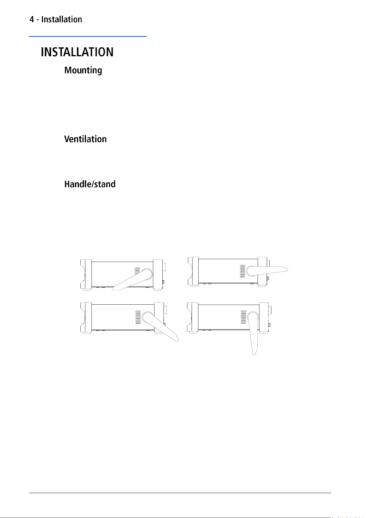
The instrument is fitted with a 4-position handle/stand. Pull out both sides of the handle at the
case pivot points, to free the position locking pegs, and rotate the handle from the stowed
position to the required stand or handle position. Release the sides of the handle to lock it in
the new position.
10 TGF4000 Series Instruction Manual
Page 12
Mains operating voltage
5.
This instrument has a universal input range and will operate from a nominal 115V or 230V
mains supply without adjustment. Check that the local supply meets the AC input requirement
given in the Specification.
Connect the instrument to the AC supply using the mains lead provided.
Should a mains plug be required for a different mains outlet socket, a suitably rated and
approved mains lead set should be used which is fitted with the required wall plug and an
IEC60320 C13 connector for the instrument end.
To determine the minimum current rating of the lead-set for the intended AC supply, refer to
the power rating information on the equipment or in the Specification.
THIS INSTRUMENT MUST BE EARTHED.
Any interruption of the mains earth conductor inside or outside the instrument will make the
instrument dangerous. Intentional interruption is prohibited.
11 TGF4000 Series Instruction Manual
Page 13

Overview
6.
① Flash drive
This is a USB Host port for the connection of flash drive which conform to the Mass Storage
Class specification. FAT16 or FAT32 filing systems are accepted.
② Colour screen
③ Power switch
④ Soft keys
The function of these keys change as the instrument is operated. The current function is shown
on the LCD in a box above each key. An empty box means that the key currently has no
function.
⑤ Setting keys
WAVES key selects the type of waveform; select from Sine, Square, Ramp, Pulse, Noise and Arb.
PARAMS (Parameters) key allows the editing of the waveform parameters.
- Mode keys
MOD (modulation), SWEEP and BURST select the operating mode. The selected key becomes
illuminated. If all mode keys are unlit the mode will be continuous carrier wave.
- Menu keys
STORES key allows access to the built-in storage for waveforms and set-ups and to a connected
flash drive.
UTILITY key gives access to menus for a variety of functions such as sync out set−up, power−up
parameters, error message settings, frequency counter and dual channel functions.
12 TGF4000 Series Instruction Manual
Page 14
Overview
⑥ Trigger/local key
TRIGGER key is used to issue a manual trigger signal. This key is also used to return to local
from remote mode.
- Channel Keys
The channel keys select the channel that is to be edited. When Channel 1 is selected the
parameter fields text and soft-key background will be orange and the CH1 key will become
illuminated, with Channel 2 these fields will change to green and the CH2 key will become
illuminated.
⑦ Output keys
The OUTPUT keys simply switch the selected MAIN OUT on or off. There are two OUTPUT keys,
one for each channel. The key becomes illuminated when the output is on and the status tab
text will change to ‘On’.
The display and key colour scheme of channel 1 is orange and channel 2 is green for ease of
identification of the currently selected channel.
⑧ Numeric keypad
Numeric keys permit direct entry of a value for the parameter currently selected.
⑨ Rotary knob & directional keys
Used during numeric entry. The left and right keys move the edit position left or right and the
knob increments or decrements the value of the selected digit.
Press and hold down any key, including soft-keys, for two seconds to access the Help page for
that key
⑩ Main out (one for each channel)
This is the 50 output from main generator. It will provide up to 20V peak−to−peak e.m.f.
which will yield 10V peak−to−peak into a matched 50 load. To maintain waveform integrity
only 50 cable should be used and the receiving end should be terminated with a 50 load. It
can tolerate a short circuit for 60 seconds.
Do not apply an external voltage to this output.
Channel 2 can also be configured to output Channel 1 sync from its MAIN OUT 2 socket. See
‘Sync output’ for more details.
13 TGF4000 Series Instruction Manual
Page 15
Connections overview
7.
①AC power inlet
② Mod in
This is the external modulation input socket for AM, FM, PM, SUM or PWM. Full-scale input is
±2.5V, frequency DC to 5MHz.
Do not apply an external voltage exceeding ±5V.
③ Ref / count (ac) in
Input for an external 10MHz reference clock and AC coupled external frequency measurement.
Input range 100mVpp – 5Vpp.
Do not apply external voltages exceeding ±10V to this signal connection.
④ Ref out
Buffered version of the 10MHz clock currently in use (internal or external). Output level
nominally 3V logic from 50
Do not apply external voltages to this output.
14 TGF4000 Series Instruction Manual
Page 16

Connections overview
⑤ Trig / count (dc) in
This is the external input for ASK, FSK, BPSK, triggered sweep, gated burst, triggered burst and
DC coupled external frequency measurement. Threshold is typically 1.2V and input sensitivity is
100mVpp.
Do not apply external voltages exceeding + 5V or –1V to this signal connection.
⑥ LAN
The LAN interface is designed to meet LXI 1.5 LXI Device Specification 2016.
Remote control using the LAN interface is possible using the TCP/IP Socket protocol. The
instrument also contains a basic Web server which provides information on the unit and allows
it to be configured. Since it is possible to misconfigure the LAN interface, making it impossible
to communicate with the instrument over LAN, a LAN Configuration Initialise (LCI) mechanism
is provided via the user interface to reset the unit to the factory default.
Further details are given in the Remote Operation chapter. For more information on LXI
standards refer to www.lxistandard.org
⑦ USB
The USB port accepts a standard USB cable. If the USB driver has been installed from the
website, the Windows plug-and-play function should automatically recognise that the
instrument has been connected. See the support page on the website for information on
installing the driver on a PC at www.aimtti.com .
Further details are given in ‘Remote operation’.
⑧ GPIB (IEEE−488) - optional
The GPIB interface is not isolated; the GPIB signal grounds are connected to the instrument
ground.
The implemented subsets are:
· SH1 AH1 T6 TE0 L4 LE0 SR1 RL1 PP1 DC1 DT1 C0 E2
The default GPIB address is 5.
Further details are given in ‘Remote operation’
15 TGF4000 Series Instruction Manual
Page 17
Using this manual
8.
This section is a general introduction to the organisation of the instrument and is intended to
be read before using the generator for the first time.
In this manual front panel keys and sockets are shown in capitals, e.g. SWEEP, MAIN OUT; all
soft-key labels, entry fields and messages displayed on the LCD are shown in a different type font, e.g. Offset, Sine.
Connect the instrument to the AC supply using the mains lead provided.
Press the power button, at power up the generator displays a start-up message whilst
initialising the application
if an error is encountered the message
Firmware Update / Battery Fail. Initialised to factory default state.
will be displayed, see ‘Information, warning and error messages’
Loading takes a few seconds, after which the carrier waveform set-up screen is displayed.
To fully disconnect from the AC supply, unplug the mains cord from the back of the instrument
or switch off at the AC supply outlet; make sure that the means of disconnection is readily
accessible. Disconnect from the AC supply when not in use.
16 TGF4000 Series Instruction Manual
Page 18

Screen layout
Once powered up the following screen will appear showing the generator parameters set to
their default values, with the MAIN OUT output set to off. Refer to ‘Utility Operations’ for how
to change the power up settings to either those at power down or to the defaults.
Both channel tabs are displayed simultaneously, the selected channel is indicated by a specified
coloured tab for easy identification; channel 1 is orange and channel 2 is green. Any channel
specific set parameters will always be shown in the specified colour for that channel. System
settings will be neutral in white, editing is also shown in white. The default layout shows the
details of the selected channel side by side, three screen layout options are available see
‘Display options’ for further details.
Status line
The Status Line indicates the status of the instrument, see ‘Status line details’ for further
information.
Parameters boxes
Shows the waveform parameter settings for the selected channel. These always include
frequency, amplitude and offset. Additional parameters shown will depend upon the
waveform type.
Graph box
Shows a representation of the waveform which the instrument is generating on the selected
channel. The parameter currently being edited is indicated by arrows.
Edit box
Shows the value of the parameter currently being edited on the selected channel. This will be a
numeric value or a parameter string.
Soft-key labels
Change as editing proceeds.
17 TGF4000 Series Instruction Manual
Page 19
Status line details
Channel tabs
The channel fields contain two types of information, selected waveform (e.g. Sine) and signal
status (On or Off). If tracking is selected, the Channel 2 field will be replaced with Tracking
CH1, if tracking with inversion is selected the field will show InvTracking CH1. The only other
exception is when calibrating the instrument, the tab will show Calibrating CH1 or Calibrating
CH2 in the specific channel tab.
Clock status
The next field indicates the external clock status.
· If the internal clock is being used, is displayed alongside INT REF.
· If an external clock is being applied or is being used, appears alongside EXT REF.
· If an external valid clock signal is detected (but not used), INT REF is followed by
EXT DET.
· If the clock source is set to external and a valid external clock signal is not detected, the
internal clock will be used by default and displayed followed by EXT ERR.
See ‘Reference clock source’ for further details on clock source.
Remote status
When the instrument is under remote control via any interface REM will be displayed.
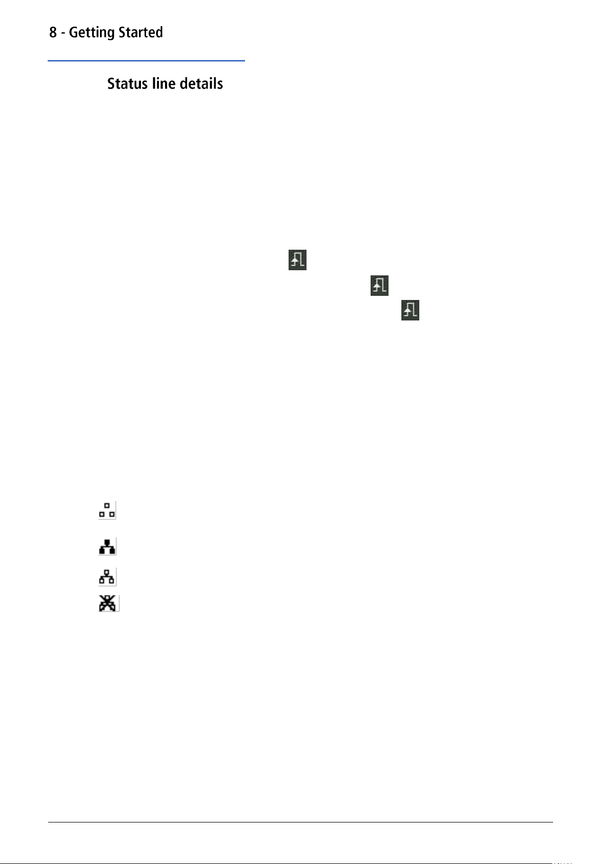
The LAN field in the Status Line can show multiple status indications:
· There is no LAN connection, for example no cable connected.
When the system is attempting to connect the icon will flash.
Successfully connected with remote control enabled.
Connected but remote control is disabled.
· Unsuccessful attempt to connect.
18 TGF4000 Series Instruction Manual
Page 20

Display options
Three different screen layout options are available, see ‘Utility Menu’ for details on how to
change the display format.
Layout 1: (Default) Shows both the parameters and the graph for the selected channel.
Layout 2: Shows the parameters for both channels simultaneously.
Layout 3: Shows the graphs for both channels simultaneously.
19 TGF4000 Series Instruction Manual
Page 21

Numeric editing
Any numeric parameter may be changed in one of the following ways:
· Enter a new value from the numeric key pad.
· Use the left and right cursor keys to select a digit position then use the knob to
Using the numeric key pad
Pressing a number key will erase the current parameter value in the Edit Box and replace it
with the current entry. The Soft-key Labels will also change to a list of units applicable to the
parameter being edited.
The examples below show frequency units and period (time) units respectively.
increment/decrement the value at that position.
During the numeric data entry, a decimal point and, if appropriate, a sign may be entered. The
+/- key is used to alternately change the sign between + and –. The left cursor key may be
used to erase the last digit entered. The entry may be cancelled by pressing the Cancel key
Once the entry is complete it may be terminated by pressing the soft-key below the required
units. The value will be checked and accepted as the new value for the relevant parameter.
20 TGF4000 Series Instruction Manual
Page 22
Numeric editing
Using the knob and cursor keys
The default settings for the knob is enabled
To disable the knob, press once to hear the click, the cursor will no longer be shown; the knob
is now disabled.
To enable the knob, press once, the first numeric parameter will be displayed with an inverse
edit cursor over one of the digits. The left and right cursor keys may be used to move the edit
cursor to any digit in the value. Values are always shown with enough digits to the right of the
decimal point to show the best resolution for the parameter.
Consecutive presses of the knob will switch between the function being enabled and disabled.
The right-most digit in a frequency value will be µHz. Depending on the actual value, one or
more digits to the left of the most significant digit displayed may be zero and will not be
shown. It is possible to move the edit cursor into these digit positions and the suppressed zeros
will be shown as in the example below.
With the edit cursor positioned at the required digit the knob may be rotated left or right to
decrement or increment the digit. As the value passes between 9 and 0 the digits to the left
will also change. In this way it is possible to set any legal value for the parameter.
Changes made by turning the knob are applied immediately to the parameter as long as the
value remains legal.
21 TGF4000 Series Instruction Manual
Page 23

Editing principles
The instrument parameters are edited using the keyboard in conjunction with the Soft-key
Labels and the Edit Box.
Generally, the required parameter is selected by pressing WAVES, PARAMS or MOD or soft-keys
or a combination of these to show the parameter in the Edit Box. The parameter is then edited
using the numeric keys, the soft-keys, the knob and cursor keys or a combination of these.
· Press the WAVES key to select the waves menu, followed by the square soft-key to select
the square-wave. Press the Duty soft-key to select the square-wave duty cycle parameter
which will show in the Edit Box. Now use the numeric keys and Soft-keys to change the
parameter as described in ‘Numeric editing’.
· Press the WAVES key to select the waves menu, followed by the sine soft-key to select
sinewave then press the MOD key to access modulation parameters. Press the Type soft-
key to select the modulation type parameter. Use the soft-keys to select the required type
from AM, FM, PM, ASK, FSK, SUM or BPSK. Press the Done soft-key to exit the menu.
Press the On/Off soft-key to turn on modulation.
· Press the WAVES key to select the waves menu, followed by the arb soft-key to select
arbitrary waveforms, followed by the Waves soft-key. Now select one of the built-in
waveforms from the soft-keys. The Edit Box will show the loaded waveform.
22 TGF4000 Series Instruction Manual
Page 24
Information, warning and error messages
Three classes of message are displayed on the screen in a Pop-up Box:
INFORMATION messages are shown to inform the user of actions that are being taken, for
example:
Please wait... the current settings are being saved
WARNING messages are shown when the entered setting causes some change which the user
might not necessarily expect. For example:
With square-wave selected at 1MHz and a Duty cycle of 25%, select sinewave and change the
frequency to 100MHz. Then select square-wave again and the message Square symmetry set
to default 50% will pop up.
ERROR messages are shown when an illegal setting is attempted, most generally a number
outside the range of values permitted. In this case the entry is rejected and the parameter
setting is left unchanged.
· Entering a frequency of 10MHz for a ramp waveform. The error message "Frequency /
Period invalid for Ramp. Frequency Upper limit 5.00MHz. Period lower limit
200.00ns" is shown.
· Entering a sinewave amplitude of 25Vpp. The error message "Invalid entry. Amplitude
Upper limit [VALUE]" is shown
· Entering a DC offset of 20V on a sinewave with an amplitude of 1.000 Vpp. The error
message "Invalid entry. Offset Upper limit [VALUE]" is shown.
The messages are shown on the display for approximately four seconds; however, pressing any
key will immediately remove the Pop-up Box and execute the function of the key which is
pressed. The last two messages can be viewed again by pressing the UTILITY, then Help key and
selecting the first or second entries from the Help menu, see ‘Help Operations’ for more
information.
Each warning and error message is accompanied by a beep. The beep may be enabled or
disabled in the UTILITY menu, under System. See ‘Beep state’ for more information.
23 TGF4000 Series Instruction Manual
Page 25
General soft-keys
often appears when editing and it always perform the same function. The key is known
as BACK and will move the soft-key labels and Edit Box up one level in the hierarchy.
The soft-key indicates that there are more options to show, press this key to show them.
In this case there is one more list of options which will show when the soft-key is pressed.
One more press of the soft-key will show the first list again.
The Done key will move back to the top level in the hierarchy.
When a soft key features a triangle, successive presses will give further options.
The Manufacturers or their agents overseas will provide a repair service for any unit developing
a fault. Where owners wish to undertake their own maintenance work, this should only be
done by skilled personnel in conjunction with the service guide which may be obtained directly
from the Manufacturers or their agents overseas.
If the instrument requires cleaning, use a cloth that is only lightly dampened with water or a
mild detergent.
To avoid electric shock, or damage to the instrument, never allow water to get inside the case.
To avoid damage to the case never clean with solvents.
24 TGF4000 Series Instruction Manual
Page 26

Waveform selection
9.
Seven types of carrier waveform can be generated:
· Sine
· Square
· Ramp
· Pulse
· Noise
· PRBS
· Arbitrary
This section deals with the use of the instrument as a simple function /arbitrary generator, i.e.
generating sine, square, ramp and arbitrary waveforms continuously with no modulation.
Pressing the WAVES key followed by any of the carrier waveform soft -keys, sine, square, ramp,
pulse, noise or arb, will immediately switch to that waveform making it available at the MAIN
OUT connector if the output is on, indicated by the OUTPUT key becoming illuminated. If the
output is not on press the OUTPUT key to turn output on.
The screen below shows the effect of pressing the WAVES key followed by the ramp soft-key.
The orange channel 1 indicator tab shows that the waveform is set to ramp and the Graph Box
has changed to show the ramp waveform.
25 TGF4000 Series Instruction Manual
Page 27
Waveform editing
Frequency
Pressing the Freq soft-key while it is highlighted will change the label to Period and time units
will be used to edit the parameter.
The upper frequency limits vary for the different waveform types; see ‘Specification’ for details.
Amplitude
Press WAVES key to return to waves menu and select a sine wave. Pressing the Ampl soft-key
shows the amplitude parameter in the Edit Box and the Graph Box changes to show that
amplitude is being edited.
The amplitude can be set in terms of peak-to-peak Volts (Vpp) from the Ampl soft key, to set
high and low levels see ‘High level and low level’. The level can be set assuming that the output
is either open-circuit or terminated.
The actual generator output impedance is always 50; the displayed amplitude values for
other load values take this into account.
26 TGF4000 Series Instruction Manual
Page 28

Waveform editing
DC offset
Pressing the Offset soft-key shows the dc offset parameter in the Edit Box and the Graph Box
changes to show that offset is being edited.
High level and low level
The instrument allows the amplitude and offset parameters to be entered in terms of high level
and low level. Pressing either the Ampl or Offset soft-key while it is highlighted will switch the
mode from amplitude/offset to high/low level. To return to amplitude/offset mode press the
highlighted HiLvl or LoLvl soft-key.
With high/low level mode selected the edit box shows the parameter, the Parameters Box
shows High Level and Low Level in place of Amplitude and Offset and the Graph Box changes to
show the parameter which is being edited.
27 TGF4000 Series Instruction Manual
Page 29

Square-wave duty cycle
With square-wave as the selected waveform, pressing the Duty soft-key shows the duty cycle
parameter in the Edit Box and the Graph Box changes to show that duty cycle is being edited.
28 TGF4000 Series Instruction Manual
Page 30
Ramp symmetry
With ramp as the selected waveform pressing the Symm soft-key shows the symmetry
parameter in the Edit Box. The Ramp waveform in the Graph Box will change to show a
representation of the shape when the symmetry is being edited.
To produce a triangle waveform set the symmetry to 50%.
29 TGF4000 Series Instruction Manual
Page 31

Output
Pressing the Output soft-key allows access to control the output parameters.
Phase
In the Output menu, press the Phase soft-key to change the start phase of the waveform. The
phase parameter will appear in the Edit Box.
The setting may be used to determine the phase difference between the two channels or
between channel 1 waveform and its carrier sync. The channels may be phase aligned by
pressing the Align soft-key. The Phase parameter is also used to set Burst Phase.
Output type
Pressing the Type soft-key on the Output menu will alternate between Normal and Inverse.
Inverse will invert the carrier waveform at the MAIN OUT connector. The output is set to
Inverted in the parameters box and the carrier waveform in the Graph Box will be inverted.
30 TGF4000 Series Instruction Manual
Page 32

Output
Range
Pressing the Range soft-key will alternate between Auto and Hold.
The instrument, by default, is in Auto mode; it auto-ranges in 6dB attenuator steps (i.e. ‘range’
maximums of 10Vpp, 5Vpp, 2.5Vpp, etc., into 50), With range set to Auto the amplifiers and
attenuators will switch automatically for optimal performance, providing best amplitude
resolution, noise and accuracy.
Selecting Hold mode disables auto-ranging; the attenuator setting is fixed for the unit’s
maximum amplitude. This can be useful in eliminating momentary disruptions in the output
waveform in Auto mode caused by the switching of the attenuators while changing the
amplitude. However, waveform quality will start to deteriorate at lower amplitudes.
With range set to Hold a fixed attenuator setting is used for all amplitude settings. The Range
field in the Parameters Box will show Attn Hold while range is held.
31 TGF4000 Series Instruction Manual
Page 33

Output
Load
Pressing the Load soft-key will show the current load value in the Edit Box.
This is the value that is assumed to be loading at the instrument MAIN OUT connector. The
value is used to calculate the actual values of amplitude and dc offset.
The output impedance of the instrument MAIN OUT connector is fixed at 50
Pressing the Load soft-key will alternate between High-Z and the last value entered. With
High-Z selected the load impedance will be assumed infinite and ‘High-z’ will appear in the
parameters box.
Press the Done soft-key to return to the top-level waveform menu.
32 TGF4000 Series Instruction Manual
Page 34

Arb waves
The instrument contains a total of sixteen arbitrary waveforms, Twelve fixed:
· Exponential Rise (ExpRis)
· Exponential Fall (ExpFal)
· Logarithmic Rise (LogRis)
· Logarithmic Fall (LogFal)
· Sinc (Sinc)
· Gaussian (Gauss)
· Lorentz (Lrntz)
· D- Lorentz (DLrntz)
· HaverSine (HvrSin)
· Cardiac (Crdiac)
· DC (DC)
· Triangle (Triang)
· Four user defined.
· There are more waveforms available on the website: www.aimtti.com
With Arb as the selected waveform, pressing the Waves soft-key switches to the Arb Waves
menu. The name of the selected arb is shown in the Edit Box and the Graph Box shows the arb
waveform.
The soft-keys allow access to all of the arbitrary waveforms in the instrument.
To select an arbitrary waveform, press the appropriate soft-key.
33 TGF4000 Series Instruction Manual
Page 35

Arb waves
Pressing the DC soft-key followed by the Done key, produces a dc only waveform at the MAIN
OUT connector.
The screen shows the result of selecting an Arb waveform with DC as the selected waveform.
The orange channel 1 status line shows DC in the Waveform field, the Graph Box shows a DC
waveform with DC offset arrows and the Edit Box contains the DC voltage menu.
34 TGF4000 Series Instruction Manual
Page 36

Arb arbs
With arb as the selected waveform, pressing the Arbs soft-key switches to the Arb/Arbs
menu.
Pressing the Load soft-key opens the load sub-menu.
The four soft-keys User1 through User4 allows direct access to the user-defined arbitrary
waveforms in the instrument. To select an arbitrary waveform, press the appropriate soft-key.
Press the Done soft-key to return to the top-level Arb menu.
35 TGF4000 Series Instruction Manual
Page 37

Arb arbs
Editing arbs
Pressing the Arbs soft-key and then Edit soft-key opens the edit sub-menu.
The instrument is capable of performing simple editing of stored arbitrary waveforms. For
more complex editing and creation of waveforms see the Waveform Manager Plus V4.13
Windows application, available on the website: www.aimtti.com
The name of the arb selected for editing is shown in the edit box. To select an arbitrary
waveform for editing press the appropriate soft-key.
The selected waveform is edited by pressing the Edit soft-key. For a full description of the
editing capabilities see ‘Editing Arbitrary Waveforms’. Press the Done soft-key to return to the
top-level Arb menu.
36 TGF4000 Series Instruction Manual
Page 38

Arb arbs
Harmonics (TGF4162 & TGF4242 only)
Pressing the Arbs soft-key and then Hrmonc soft-key opens the harmonic waveform submenu.
The instrument is capable of creating waveforms by the addition of sine wave harmonics. Up to
16 harmonics can be used, chosen from up to the 50th order. The amplitude and phase can be
individually set for each harmonic. Harmonic waveforms can also be created or edited in the
Waveform Manager Plus V4.13 Windows application supplied on the website: www.aimtti.com
The created harmonic waveform will be stored in one of the four user-defined arbitrary
waveform locations. The name of the arb selected for storing the harmonic waveform is shown
in the Edit Box. To select an arbitrary waveform location for storing the harmonic waveform
press the appropriate soft-key. For a full description of the harmonic waveform capabilities see
‘Harmonic Waveforms’.
Any previous waveform stored in the same location will be erased.
Press the Done soft-key to return to the top-level Arb menu.
37 TGF4000 Series Instruction Manual
Page 39

Arb arbs
Filter (TGF4162 & TGF4242 only)
Pressing the Arbs soft-key and then Filter soft-key opens the arbitrary waveform filter menu.
The instrument includes two filters to smooth transitions between points as arbitrary
waveforms are generated. The Step filter has a nearly ideal step response, but with more rolloff in its frequency response than the Normal filter. The Normal filter has a wide, flat frequency
response, but its step response exhibits overshoot and ringing.
The current filter band-width is shown in the Edit Box. To select between the two available
filters, press the appropriate soft-key.
Press the Done soft-key to return to the top-level Arb menu.
38 TGF4000 Series Instruction Manual
Page 40

Sync output
Channel 2 can be configured to output Channel 1 sync from its MAIN OUT 2 socket. Sync is a
multi-function output which is automatically selected based on the current instrument set-up.
Alternatively, user can choose Sync to always be carrier referenced, to output the currently
used trigger signal or turn it off.
· Carrier Sync: A square wave at the same frequency as the carrier
waveform. Available for all waveforms except Noise.
· Modulation Sync: A square-wave at the same frequency as the internal
modulation waveform with a duty of 50%. Not available for
external modulation.
· Sweep Sync: A square wave at the sweep rate.
· Burst Sync: A square wave coincident with a burst output.
· Trigger: A buffered version of the Trigger signal.
The selection of the signals themselves and configuration of channel 2 as channel 1 sync is
discussed in the ‘Utility Menu’. By default, the automatic selection is enabled which will choose
the most relevant output for the instrument set-up. However, it is possible to override the
automatic setting. See ‘Utility Menu’ for more information.
39 TGF4000 Series Instruction Manual
Page 41

Pulse application
10.
The pulse generator can produce a wide range of pulses with adjustable period, width, and
edge speed. It may also be set in Gated or Burst mode or modulated using PWM; for more
information see ‘Modulation’ section and ‘Burst’ section.
Each channel has an independent pulse generator. These may be set to any combination of
period, width and modulation or burst. However, when the channels are linked by one of the
dual-channel functions there are some restrictions between the parameters of the two
channels; see the Dual-Channel Operations in ‘Specification’ for details.
Pressing the WAVES key followed by the Pulse soft-key will switch to the pulse waveform. The
screen below shows the effect of selecting pulse.
The PlsFrq soft-key allows setting of the pulse frequency. Pressing the key while it is
highlighted will change it to PlsPer and the pulse period may be entered. The pulse generator
uses its own value for pulse frequency/pulse period. Changing it will not affect the
frequency/period value of the other carrier waveforms.
Amplitude and dc offset are adjusted in the same way as for sine waves and they may also be
set in terms of high level and low level.
Pressing the Duty/Width soft-key allows the pulse duty or width to be set.
40 TGF4000 Series Instruction Manual
Page 42

Pulse width
Pressing the Duty soft-key while it is highlighted changes the editable parameter to Width, the
Width parameter is shown in the Edit Box in terms of time (ns, μs, ms, or s) The value
represents the time from the mid-point of the rising edge to the mid-point of the falling edge,
the Graph Box changes to show that width is being edited and the value is shown in the
parameters box.
Pressing the Width soft-key while it is highlighted changes the editable parameters to Duty,
the Duty parameter is shown in the Edit Box as the width of the pulse as a percentage of the
period to a maximum resolution of 0.01%, the Graph Box changes to show that width is being
edited and the value is shown in the parameters box.
41 TGF4000 Series Instruction Manual
Page 43

Edge times
To amend edge times, press the More soft-key to show more options and select Edge.
The edge time represents the time between the 10% and 90% points on the pulse edges. Rise
time and fall time can be coupled or adjusted independently.
Pressing the Mode soft-key toggles between Independent or Coupled mode. When Coupled
mode is selected the Edge soft key is available, this edits both rise and fall parameters
together. When selecting Independent mode, Edge is replaced by with two soft-keys; Rise and
Fall and these parameters can be edited independently. The graph box changes to show the
parameters being edited.
The parameters box will show Rise and Fall at all times, the values will change depending on
whether coupled or independent mode has been selected.
42 TGF4000 Series Instruction Manual
Page 44

Pulse delay
Pressing the Delay soft-key shows the delay parameter in the Edit Box, the Graph Box changes
to show that delay is being edited and the Delay setting is shown in the parameters box.
The Graph box shows the delay parameter between the arrows.
Delay can be specified in terms of time (ns, us, ms or s) Changing the delay causes the start of
the pulse to be delayed with respect to the sync pulse available at the SYNC OUT connector.
The delay also adds a delay between the trigger signal and the pulse output during burst
modes. See ‘Burst’ for more details of Burst and Gate modes. The delay also changes the
relative timings of the pulses in dual channel modes.
43 TGF4000 Series Instruction Manual
Page 45

Carrier wave noise
11.
The instrument contains a wide-band Gaussian white noise generator for each channel which
may be used in the following ways:
· As the main output from the carrier wave generator
· As a modulating waveform
· Added as a percentage to the current output waveform using SUM modulation.
These options are described in the following sections. In dual channel mode there are some
restrictions on Noise; see Dual-Channel Operations in ‘Specification’ for details.
Pressing the WAVES key, followed by the Noise soft-key will switch to the Noise/PBRS function
and show the screen below.
It is possible to edit these parameters in terms of high level and low level by pressing the Ampl
key.
Pressing the Source soft-key shows the following and allows either noise or the PRBS function
to be selected. Press Noise to select the Noise function. Press Done to exit the Source menu.
44 TGF4000 Series Instruction Manual
Page 46

Noise modulation
High level and low level
The instrument allows the amplitude and offset parameters to be entered in terms of high level
and low level. Pressing either the Ampl or Offset soft-key while it is highlighted will switch the
mode from amplitude/offset to high/low level. To return to amplitude/offset mode press the
highlighted HiLvl or LoLvl soft-key.
With high/low level mode selected the edit box shows the parameter, the Parameters Box
shows High Level and Low Level in place of Amplitude and Offset and the Graph Box changes to
show the parameter which is being edited
Noise may be used as a modulation shape in the same way as sine or ramp etc. Noise can also
be used as a carrier wave for amplitude and sum modulation and for amplitude shift keying.
See ‘Modulation’ for more information.
45 TGF4000 Series Instruction Manual
Page 47

Carrier wave PRBS
12.
(TGF4162 & TGF4242 only)
The instrument contains a PRBS (Pseudo Random Binary Sequence) generator for each channel
which may be used in the following ways:
· As the main output from the carrier wave generator
· As a modulating waveform
These options are described in the following sections. In dual channel mode there are some
restrictions on PRBS; see Dual-Channel Operations in ‘Specification’ for details.
Pressing the WAVES key, followed by the Noise soft-key will switch to the Noise/PBRS function.
Pressing the Source soft-key shows the following. Press PRBS to select the PRBS function.
Press Done to exit the Source menu.
Press the Type soft-key to set PRBS type. The soft-keys PN7, PN9, PN11, PN15, PN20, PN23,
PN29 and PN31 set the number of bits used to generate the PRBS.
Choosing a PRBS type and pressing the Done soft-key shows the PRBS edit menu.
46 TGF4000 Series Instruction Manual
Page 48

PRBS modulation
Use the BitRate soft-key to set the rate at which the PRBS generator is clocked.
Use the Ampl and Offset soft-keys to set these parameters as for any other carrier wave.
PRBS may be modulated or used as a modulation shape in the same way as sine or ramp, etc.
See ‘Modulation’ for more information.
47 TGF4000 Series Instruction Manual
Page 49

Modulation
type
Carrier waveform
Internal waveform shapes
Sine
Square
Ramp
Pulse
Noise
Arb
PBRS*
AM (AM-SC)
• • • • • • •
Sine, Square, Positive Ramp,
Negative Ramp, Triangle,
Gaussian Noise, DC, Sinc,
Exponential Rise/ Fall,
Logarithmic Rise/ Fall, Haversine,
Gaussian, Lorentz, D-Lorentz,
Cardiac & User Defined Arbs
FM
• • •
•
PM
• • •
•
ASK
• • • • • • •
Square
FSK
• • •
•
BPSK
• • •
•
PWM
•
Sine, Square, Positive Ramp,
Negative Ramp, Triangle,
Gaussian Noise, DC, Sinc,
Exponential Rise/ Fall,
Logarithmic Rise/ Fall, Haversine,
Gaussian, Lorentz, D-Lorentz,
Cardiac & User Defined Arbs
SUM*
• • • • • • •
*TGF4162 & TGF4242 only
Modulation application
13.
The instrument can apply nine types of modulation:
· Amplitude Modulation (AM)
· Amplitude Modulation – Suppressed Carrier (AM-SC)
· Frequency Modulation (FM)
· Phase Modulation (PM)
· Amplitude Shift Keying (ASK)
· Frequency Shift Keying (FSK)
· Binary Phase Shift Keying (BPSK)
· Pulse Width Modulation (PWM)
· SUM (Carrier plus Modulating signal)
Only one modulation type may be applied at any one time.
Not all modulation types can be applied to a selected carrier waveform.
48 TGF4000 Series Instruction Manual
Page 50

Modulation application
Pressing the MOD key will allow access to control the modulation parameters. Pressing the
On/Off soft-key will apply the currently selected modulation to the currently selected carrier
waveform and the MOD key will become illuminated.
The screen below shows the effect of pressing the On/Off soft-key when Sine is the selected
waveform, Internal is the selected (default) source and the selected modulation type is AM.
The Parameters Box on the right-hand side now shows AM in the Modulation field and the
current modulation parameters of AM Freq, Depth and Shape. The Graph Box shows the
modulating waveform below a representation of the modulated carrier waveform.
To change the carrier waveform parameters, press the WAVES key, followed by the waveform
required. Notice that AM still shows in the Modulation field of the Parameters Box and the
MOD key still glows, indicating that modulation is still active. To return to the modulation menu
to edit the modulation parameters press the MOD key again. To turn off modulation press the
On/Off soft-key in the modulation menu.
When modulation is enabled any sweep or burst applications will be disabled.
49 TGF4000 Series Instruction Manual
Page 51

Amplitude modulation (AM)
To select amplitude modulation, press the MOD key to access the modulation menu and then
press the Type soft-key to show the display below.
The soft-keys present all of the available modulation types.
If amplitude modulation is not already selected press the AM soft-key to access the amplitude
modulation sub-menu.
Carrier waveform suppression
The instrument supports two types of amplitude modulation, ‘normal’ and double sideband
suppressed carrier. In suppressed carrier amplitude modulation, the carrier is not present
unless the modulating signal has an amplitude greater than zero.
Select from the two types of amplitude modulation and then press soft-key.
Press the Done key to return to the top-level modulation menu.
Press On/Off soft-key to apply the selected modulation.
50 TGF4000 Series Instruction Manual
Page 52

Amplitude modulation (AM)
Modulation source
To select the modulation source, press the Source soft-key, the options are Internal or
External.
Internal will use the waveform specified in the shape parameter and the Graph Box will show
that shape as the modulating waveform.
External will use the signal present at the MOD IN connector and the Freq and Shape
parameters will no longer be editable. The Graph Box will always show a sinewave as the
modulating waveform if the source is set to External.
51 TGF4000 Series Instruction Manual
Page 53

Amplitude modulation (AM)
Modulation depth
To set the modulation depth press the Depth soft-key. The Depth parameter will appear in the
Edit Box and the modulating waveform in the Graph Box will show that depth is being edited.
Modulation frequency
To set the modulation frequency press the Freq soft-key. The frequency parameter will appear
in the Edit Box and the modulating waveform in the Graph Box will show that frequency is
being edited.
52 TGF4000 Series Instruction Manual
Page 54

Amplitude modulation (AM)
Modulation shape
To set the modulation shape press the Shape soft-key. The currently selected shape will appear
in the Edit Box and the soft-keys will change to a list of shapes available.
Select the modulation shape required by pressing the appropriate key then press the Done
soft-key to return to the top-level modulation menu.
All the parameters for amplitude modulation are now set.
53 TGF4000 Series Instruction Manual
Page 55

Frequency modulation (FM)
To select frequency modulation, press the MOD key to access the modulation menu and then
press the Type soft-key to show the display below.
The soft-keys present all of the available modulation types.
If frequency modulation is not already selected press the FM soft-key followed by the Done
key to return to the top-level modulation menu.
Press On/Off soft-key to apply the selected modulation.
54 TGF4000 Series Instruction Manual
Page 56

Frequency modulation (FM)
Modulation source
To select the modulation source, press the Source soft-key, the options are Internal or
External.
Internal will use the waveform specified in the shape parameter and the Graph Box will show
that shape as the modulating waveform.
External will use the signal present at the MOD IN connector and the Freq and Shape
parameters will no longer be editable. The Graph Box will always show a sinewave as the
modulating waveform if the source is set to External.
55 TGF4000 Series Instruction Manual
Page 57

Frequency modulation (FM)
Frequency deviation
To set the frequency deviation press the Deviatn soft-key. The deviation parameter will appear
in the Edit Box and the modulating waveform in the Graph Box will show that deviation is being
edited.
Modulation frequency
To set the modulation frequency press the Freq soft-key. The frequency parameter will appear
in the Edit Box and the modulating waveform in the Graph Box will show that frequency is
being edited.
56 TGF4000 Series Instruction Manual
Page 58

Frequency modulation (FM)
Modulation shape
To set the modulation shape press the Shape soft-key. The currently selected shape will appear
in the Edit Box and the soft-keys will change to a list of shapes available.
Select the modulation shape required by pressing the appropriate key then press the Done
soft-key to return to the top-level modulation menu.
All the parameters for frequency modulation are now set.
57 TGF4000 Series Instruction Manual
Page 59

Phase modulation (PM)
To select phase modulation, press the MOD key to access the modulation menu and then press
the Type soft-key to show the display below.
The soft-keys present all of the available modulation types.
If phase modulation is not already selected press the PM soft-key followed by the Done key to
return to the top-level modulation menu.
Press On/Off soft-key to apply the selected modulation.
58 TGF4000 Series Instruction Manual
Page 60

Phase modulation (PM)
Modulation source
To select the modulation source, press the Source soft-key, the options are Internal or
External.
Internal will use the waveform specified in the shape parameter and the Graph Box will show
that shape as the modulating waveform.
External will use the signal present at the MOD IN connector and the Freq and Shape
parameters will no longer be editable. The Graph Box will always show a sinewave as the
modulating waveform if the source is set to External.
59 TGF4000 Series Instruction Manual
Page 61

Phase modulation (PM)
Phase deviation
To set the phase deviation press the Deviatn soft-key. The deviation parameter will appear in
the Edit Box and the modulating waveform in the Graph Box will show that deviation is being
edited.
Modulation frequency
To set the modulation frequency press the Freq soft-key. The frequency parameter will appear
in the Edit Box and the modulating waveform in the Graph Box will show that frequency is
being edited.
60 TGF4000 Series Instruction Manual
Page 62

Phase modulation (PM)
Modulation shape
To set the modulation shape press the Shape soft-key. The currently selected shape will appear
in the Edit Box and the soft-keys will change to a list of shapes available.
Select the modulation shape required by pressing the appropriate key then press the Done
soft-key to return to the top-level modulation menu.
All the parameters for phase modulation are now set.
61 TGF4000 Series Instruction Manual
Page 63

Amplitude shift keying (ASK)
To select amplitude shift keying, press the MOD key to access the modulation menu and then
press the Type soft-key to show the display below.
The soft-keys present all of the available modulation types.
If ASK is not already selected press the ASK soft-key followed by the Done key to return to the
top-level modulation menu.
Press On/Off soft-key to apply the selected modulation.
62 TGF4000 Series Instruction Manual
Page 64

Amplitude shift keying (ASK)
Modulation source
To select the modulation source, press the Source soft-key, the options are Internal or
External.
Internal will use an internally generated trigger signal.
External will use the signal present at the TRIG / COUNT (DC) IN connector and the Rate
parameter will no longer be editable. The Graph Box will show a switching carrier and a squarewave as the modulating waveform irrespective of the source of the switching signal.
63 TGF4000 Series Instruction Manual
Page 65

Amplitude shift keying (ASK)
Hop amplitude
Amplitude shift keying will generate the carrier amplitude while the switching signal is false
and the hop amplitude while the switching signal is true. To set the hop amplitude press the
HpAmpl soft-key. The hop amplitude parameter will appear in the Edit Box.
Switching rate
To set the switching rate press the Rate soft-key. The rate parameter will appear in the Edit Box
and the modulating waveform in the Graph Box will show that the switching rate is being
edited.
64 TGF4000 Series Instruction Manual
Page 66

Amplitude shift keying (ASK)
Hop polarity
To set which level of the switching signal will output the hop amplitude press the HopPol softkey. The currently selected polarity will appear in the Edit Box.
The options are Positive or Negative.
Setting Positive will cause ASK to generate the hop amplitude while the switching signal is high
and the carrier amplitude while the switching signal is low.
Setting Negative will cause ASK to generate the hop amplitude while the switching signal is low
and the carrier amplitude while the switching signal is high.
All the parameters for amplitude shift keying are now set.
65 TGF4000 Series Instruction Manual
Page 67

Frequency shift keying (FSK)
To select frequency shift keying press the MOD key to access the modulation menu and then
press the Type soft-key to show the display below.
The soft-keys present all of the available modulation types.
If frequency shift keying is not already selected press the FSK soft-key followed by the Done
key to return to the top-level modulation menu.
Press On/Off soft-key to apply the selected modulation.
66 TGF4000 Series Instruction Manual
Page 68

Frequency shift keying (FSK)
Modulation source
To select the modulation source, press the Source soft-key, the options are Internal or
External.
Internal will use an internally generated trigger signal.
External will use the signal present at the TRIG / COUNT (DC) IN connector and the Rate
parameter will no longer be editable. The Graph Box will show a switching carrier and a squarewave as the modulating waveform irrespective of the source of the switching signal.
67 TGF4000 Series Instruction Manual
Page 69

Frequency shift keying (FSK)
Hop frequency
Frequency shift keying will generate the carrier frequency while the switching signal is false and
the hop frequency while the switching signal is true. To set the hop frequency press the
HopFrq soft-key. The hop frequency parameter will appear in the Edit Box and the modulating
waveform in the Graph Box will show that hop frequency is being edited.
Switching rate
To set the switching rate press the Rate soft-key. The rate parameter will appear in the Edit Box
and the modulating waveform in the Graph Box will show that the switching rate is being
edited.
68 TGF4000 Series Instruction Manual
Page 70

Frequency shift keying (FSK)
Hop polarity
To set which level of the switching signal will output the hop frequency press the HopPol soft-
key. The currently selected polarity will appear in the Edit Box.
The options are Positive or Negative.
Setting Positive will cause FSK to generate the hop frequency while the switching signal is high
and the carrier frequency while the switching signal is low.
Setting Negative will cause FSK to generate the hop frequency while the switching signal is low
and the carrier frequency while the switching signal is high.
All the parameters for frequency shift keying are now set.
69 TGF4000 Series Instruction Manual
Page 71

Binary phase shift keying (BPSK)
To select BPSK press the MOD key to access the modulation menu and then press the Type
soft-key to show the display below.
The soft-keys present all of the available modulation types.
If binary phase shift keying is not already selected press the BPSK soft-key followed by the
Done key to return to the top-level modulation menu.
Press On/Off soft-key to apply the selected modulation.
70 TGF4000 Series Instruction Manual
Page 72

Binary phase shift keying (BPSK)
Modulation source
To select the modulation source, press the Source soft-key, the options are Internal or
External.
Internal will use an internally generated trigger signal.
External will use the signal present at the TRIG / COUNT (DC) IN connector and the Rate
parameter will no longer be editable. The Graph Box will show a switching carrier and a squarewave as the modulating waveform irrespective of the source of the switching signal.
71 TGF4000 Series Instruction Manual
Page 73

Binary phase shift keying (BPSK)
Hop phase
Binary phase shift keying will generate the carrier phase while the switching signal is false and
the hop phase while the switching signal is true. To set the hop phase press the HopPhs softkey. The hop phase parameter will appear in the Edit Box.
Switching rate
To set the switching rate press the Rate soft-key. The rate parameter will appear in the Edit Box
and the modulating waveform in the Graph Box will show that the switching rate is being
edited.
72 TGF4000 Series Instruction Manual
Page 74

Binary phase shift keying (BPSK)
Hop polarity
To set which level of the switching signal will output the hop phase press the HopPol soft-key.
The currently selected polarity will appear in the Edit Box.
The options are Positive or Negative.
Setting Positive will cause BSPK to generate the hop phase while the switching signal is high
and the carrier phase while the switching signal is low.
Setting Negative will cause BPSK to generate the hop phase while the switching signal is low
and the carrier phase while the switching signal is high.
All the parameters for binary phase shift keying are now set.
73 TGF4000 Series Instruction Manual
Page 75

SUM modulation
To select SUM modulation, press the MOD key to access the modulation menu and then press
the Type soft-key to show the display below.
The soft-keys present all of the available modulation types.
If SUM modulation is not already selected press the SUM soft-key followed by the Done key to
return to the top-level modulation menu.
Press On/Off soft-key to apply the selected modulation.
74 TGF4000 Series Instruction Manual
Page 76

SUM modulation
Modulation source
To select the modulation source, press the Source soft-key, the options are Internal or
External.
Internal will use the waveform specified in the shape parameter and the Graph Box will show
that shape as the modulating waveform.
External will use the signal present at the MOD IN connector and the Freq and Shape
parameters will no longer be editable. The Graph Box will always show a sinewave as the
modulating waveform if the source is set to External.
75 TGF4000 Series Instruction Manual
Page 77

SUM modulation
Modulation level
To set the modulation Level press the Level soft-key. The parameter will appear in the Edit Box
and the modulating waveform in the Graph Box will show that Modulation Level is being
edited.
Modulation frequency
To set the modulation frequency press the Freq soft-key. The frequency parameter will appear
in the Edit Box and the modulating waveform in the Graph Box will show that frequency is
being edited.
76 TGF4000 Series Instruction Manual
Page 78

SUM modulation
Modulation shape
To set the modulation shape press the Shape soft-key. The currently selected shape will appear
in the Edit Box and the soft-keys will change to a list of shapes available.
Select the modulation shape required by pressing the appropriate key then press the Done
soft-key to return to the top-level modulation menu.
All the parameters for SUM modulation are now set.
77 TGF4000 Series Instruction Manual
Page 79

Pulse width modulation (PWM)
Pulse width modulation is applicable to pulse only. Select Pulse then select PWM by pressing
the MOD key to access the modulation menu and then press the Type soft-key to show the
display below.
The soft-keys present all of the available modulation types.
PWM can only be applied to Pulse carrier waveform.
If PWM is not already selected press the PWM soft-key followed by the Done key to return to
the top-level modulation menu.
Press On/Off soft-key to apply the selected modulation.
78 TGF4000 Series Instruction Manual
Page 80

Pulse width modulation (PWM)
Modulation source
To select the modulation source, press the Source soft-key, the options are Internal or
External.
Internal will use the waveform specified in the shape parameter and the Graph Box will show
that shape as the modulating waveform.
External will use the signal present at the MOD IN connector and the Freq and Shape
parameters will no longer be editable. The Graph Box will always show a sinewave as the
modulating waveform if the source is set to external.
79 TGF4000 Series Instruction Manual
Page 81

Pulse width modulation (PWM)
Pulse width deviation
To set the pulse width deviation press the Dev % soft-key. The deviation parameter will appear
in the Edit Box and the modulating waveform in the Graph Box will show that deviation is being
edited.
Modulation frequency
To set the modulation frequency press the Freq soft-key. The frequency parameter will appear
in the Edit Box and the modulating waveform in the Graph Box will show that frequency is
being edited.
80 TGF4000 Series Instruction Manual
Page 82

Pulse width modulation (PWM)
Modulation shape
To set the modulation shape press the Shape soft-key. The currently selected shape will appear
in the Edit Box and the soft-keys will change to a list of shapes available.
Select the modulation shape required by pressing the appropriate key then press the Done
soft-key to return to the top-level modulation menu.
All the parameters for pulse width modulation are now set.
81 TGF4000 Series Instruction Manual
Page 83

Sweep application
14.
The sweep function allows the carrier frequency to be swept using small frequency steps from
the start frequency to the stop frequency. There are over 4000 steps and this remains constant
for all sweep times and frequency spans.
All waveforms can be swept with the exception of Pulse, Noise and PRBS
To select sweep, press the SWEEP key to access the sweep menu and then press the On/Off
soft-key to apply the currently selected sweep parameters to the currently selected carrier
waveform. The SWEEP key will become illuminated when sweep is activated.
The screen below shows the effect of enabling sweep when sine is the selected waveform.
The Parameters Box now shows the current sweep parameters of Sweep time, Start, Stop and
Time, and Sweeping is shown in the Frequency field. The Graph Box shows the sweep
waveform type below a representation of the swept carrier waveform. The Edit Box contains
the selected parameter, in this case sweep time.
82 TGF4000 Series Instruction Manual
Page 84

Sweep application
To change the carrier waveform parameters, press the WAVES key, followed by the waveform
required.
Notice that Sweeping still shows in the Frequency field of the Parameters Box and the SWEEP
key still glows, indicating that sweep is still active.
It is still possible to edit amplitude and dc offset in the PARAMS menu
To return to the Sweep menu to edit the sweep parameters press the SWEEP key again. To turn
off sweep press the On/Off soft-key in the sweep menu.
83 TGF4000 Series Instruction Manual
Page 85

Sweep type
To see the sweep settings in the parameters box, sweep must be activated. To activate sweep.
press the On/Off soft key.
To set the sweep type press the Type soft-key. The currently selected type will appear in the
Edit Box and soft-keys will change to a list of sweep types available.
The arrows indicate up or down sweeps. With any of the Lin types selected the sweep changes
the frequency at a linear rate; with log types selected the sweep spends an equal time in each
frequency decade. The up arrows indicate a sweep from start frequency to stop frequency. The
down arrows indicate a sweep from stop frequency to start frequency.
Select the sweep type required by pressing the appropriate key then press the Done soft-key
to return to the top-level sweep menu.
84 TGF4000 Series Instruction Manual
Page 86

Sweep type
Start and stop frequency
Press Freq soft-key to access sweep frequency parameters. To set the start or stop frequency
press the Start or Stop soft-keys.
The frequency parameter will appear in the Edit Box and the sweep waveform type in the
Graph Box will show that start or stop frequency is being edited.
The start frequency must be lower than the stop frequency, if this is not the case an error will
be generated
85 TGF4000 Series Instruction Manual
Page 87

Sweep type
Centre and span
The instrument also allows the start and stop frequency parameters to be entered in terms of
centre and span. Pressing either the Start or Stop soft-key while it is highlighted will switch the
mode from start/stop to centre/span.
With centre/span mode selected the Edit Box shows the parameter, the Parameters Box shows
Centre and Span in place of Start and Stop and the Graph Box changes to show the parameter
which is being edited.
To return to start/stop mode press the highlighted Centre or Span soft-key.
Press the Done soft-key to return to the top-level sweep menu.
86 TGF4000 Series Instruction Manual
Page 88

Sweep time
To set the sweep time press the Time soft-key. The time parameter will appear in the Edit Box
and the Graph Box will show that sweep time is being edited.
The sweep mode specifies how the sweep will be started. This may be continuous or triggered.
The trigger signal for the sweep can be internal from the trigger generator, external from the
TRIG / COUNT (DC) IN connector or manual by pressing the TRIGGER key.
To set the mode press the Mode soft-key. The mode parameter will appear in the Edit Box.
Continuous sweep
The default mode is continuous sweep. In this mode the sweep will proceed to the end and
immediately start again with no pause.
87 TGF4000 Series Instruction Manual
Page 89

Sweep mode
Triggered sweep
Pressing the Mode soft-key again will change the mode to triggered sweep.
In this mode the sweep will proceed to the end and then waits for a trigger to start again. The
soft-keys will change and a trigger waveform will be added to the Graph Box. The Sweep Type
field in the Parameters Box will show that the sweep is now triggered.
When the mode is set to triggered mode, SetTrg soft-key appears in the sweep main menu to
allow access to control and set the sweep trigger parameters. Press the SetTrg soft-key to set
trigger parameters.
88 TGF4000 Series Instruction Manual
Page 90

Sweep mode
Press the Source key to set trigger source. The three possible trigger sources are:
· Internal Trigger - using the internal trigger generator
· External Trigger - using the signal at the TRIG / COUNT (DC) IN connector
· Manual Trigger - from the Trigger key.
Select the trigger source then press soft-key.
Pressing the Period soft-key allows the period of the internal trigger generator to be set. The
Edit Box shows the current period and the Graph Box changes to show that the trigger period is
being edited.
89 TGF4000 Series Instruction Manual
Page 91

Sweep mode
When the source is external trigger, the Period soft-key is replaced by Slope soft-key.
Repeated presses of the Slope soft-key key select between Positive Slope and Negative Slope.
The trigger waveform in the Graph Box changes to show the edge in use.
When the source is manual trigger, there are no additional parameters to be set. Press the
TRIGGER key to send a manual trigger. Press the Done soft-key to return to the top-level sweep
menu.
All the parameters for sweep are now set.
90 TGF4000 Series Instruction Manual
Page 92

Overview
15.
The burst function allows the carrier waveform to be triggered, produce a user specified
number of cycles and then stop and wait for the next trigger.
For a PRBS waveform burst the count is the PRBS bit-rate and not the PRBS cycles. This allows
the generation of incomplete or multiple sequences. A new trigger always restarts the PRBS
from the start.
Alternatively, the number of cycles may be Infinite. In this case the trigger starts the waveform.
As above, PRBS waveforms will be triggered from the start.
For a noise waveform, the noise generation will be reset to its start condition when triggered.
This allows it to generate the same random noise sequence again without the need to wait for
the repetition time to elapse.
The Gated Burst function causes the carrier waveform to run while the trigger is true and stop
while the trigger is false. The gated function is also available with Noise as the carrier
waveform.
In all the above cases, except Noise and PRBS, the operation will always produce an exact
number of cycles of the carrier waveform.
The trigger signal for the burst can be internal from the trigger generator, external from the
TRIG / COUNT (DC) IN connector or manual by pressing the TRIGGER key.
91 TGF4000 Series Instruction Manual
Page 93

Burst application
To select burst, press the BURST key to access the burst menu and then press the On/Off softkey to apply the currently selected burst parameters to the currently selected carrier
waveform. The BURST key will become illuminated.
The screen below shows the effect of enabling burst when sine is the selected waveform.
The Parameters Box now shows the current burst parameters of Burst, Source, Period, and
Count, and Triggered is shown in the Burst field. The Graph Box shows the burst waveform
trigger below a representation of the carrier waveform. The Edit Box contains the selected
parameter, in this case Type.
To change the carrier waveform parameters, press the WAVES key, followed by the waveform
required.
Notice that Triggered still shows in the Burst field of the Parameters Box and the BURST key
still glows, indicating that burst is still active. To return to the Burst menu to edit the burst
parameters press the BURST key again. To turn off burst press the On/Off soft-key in the burst
menu.
92 TGF4000 Series Instruction Manual
Page 94

Burst type
To set the burst type press the Type soft-key.
Pressing the Type soft-key while it is highlighted will change the type from Triggered Burst to
Gated Burst and vice-versa.
The currently selected type will appear in the Edit Box, the Burst field in the Parameters Box
will show the type and the Graph Box will show the trigger waveform below a representation of
the carrier waveform with the burst type applied.
93 TGF4000 Series Instruction Manual
Page 95

Burst count
To set the burst count press the Count soft-key. The burst count parameter will appear in the
Edit Box.
Only Triggered Burst has a Count soft-key.
The carrier waveform in the Graph Box will show a representation of the burst as the count is
edited.
When a value of more than 3 cycles is selected, the graph box will show ****** to
represent this.
Press the Count soft-key again to change the count from a finite number to infinite count.
When the number of cycles is infinite, the trigger starts the waveform. Press the Restart softkey to stop the waveform and wait for a trigger to re-start the waveform.
94 TGF4000 Series Instruction Manual
Page 96

Burst phase
Press the Count soft-key again to change the count back to finite count.
To set the carrier start phase, press the WAVES key, followed by the waveform required, which
will return the display to the carrier menu and then press the Output soft-key.
In the Output menu, press the Phase soft-key to change the start phase of the waveform. The
phase parameter will appear in the Edit Box.
The carrier waveform in the Graph Box will show a representation of the carrier start phase as
the phase is edited.
Press the highlighted BURST key to return the display to the burst menu.
95 TGF4000 Series Instruction Manual
Page 97

Burst triggering
Press the SetTrg soft-key in the burst menu to allow access to control and set the burst trigger
parameters.
Press the Source key to set trigger source. The three possible trigger sources are:
· Internal Trigger - using the internal trigger generator
· External Trigger - using the signal at the TRIG / COUNT (DC) IN connector
· Manual Trigger - from the Trigger key
Select the trigger source then press soft-key.
96 TGF4000 Series Instruction Manual
Page 98

Burst triggering
Period can only be set for Internal Trigger.
Pressing the Period soft-key allows the period of the internal trigger generator to be set. The
Edit Box shows the current period and the Graph Box changes to show that the trigger period is
being edited.
Slope can only be set for External Trigger.
When the source is external trigger, the Period soft-key is replaced by Slope soft-key.
97 TGF4000 Series Instruction Manual
Page 99

Burst triggering
Repeated presses of the Slope soft-key will select between Positive Slope and Negative Slope.
The trigger waveform in the Graph Box changes to show the edge in use.
When the source is manual trigger, there are no additional parameters to be set. Press the
TRIGGER key to send a manual trigger. Press the Done soft-key to return to the top-level burst
menu.
All the parameters for burst are now set.
98 TGF4000 Series Instruction Manual
Page 100

Channel selection
16.
The instrument incorporates two separate generators in which all parameters can be set
independently of each other.
The two generators use the same system clock and share a single Trigger Input and Modulation
Input on the rear panel.
Press the CH 1 or CH 2 key to select between channels for parameter editing.
The selected channel is indicated by a specified colour for easy identification.
Channel 1 is orange:
Channel 2 is green:
Any channel specific set parameters will always be shown in the specified colour for that
channel.
System settings will be neutral in white, editing is also shown in white.
99 TGF4000 Series Instruction Manual
 Loading...