

Page 1

INSTRUCTION MANUAL
EN
SMU4000 SERIES
SOURCE MEASURE UNITS
Page 2

CONTENTS
CONTENTS ............................................................................................................................................................ 1
Product description ..................................................................................................................................... 4
Safety ............................................................................................................................................................. 5
Symbols .......................................................................................................................................................................... 5
Safety notices ................................................................................................................................................................. 6
Installation .................................................................................................................................................... 7
Mounting ......................................................................................................................................................................... 7
Ventilation ....................................................................................................................................................................... 7
Handle/stand .................................................................................................................................................................. 7
Electrical Requirements .................................................................................................................................................. 8
Switching On .................................................................................................................................................................. 9
Instrument overview .................................................................................................................................... 10
Front Panel ................................................................................................................................................................... 10
Rear Panel .................................................................................................................................................................... 12
Introduction .................................................................................................................................................. 14
Using this Manual ......................................................................................................................................................... 14
Navigation Controls ...................................................................................................................................................... 15
Home screen ................................................................................................................................................................ 17
Getting Started ............................................................................................................................................. 19
Connections .................................................................................................................................................................. 19
High Voltage Interlock [SMU4201 only] ........................................................................................................................ 20
Basic operation ............................................................................................................................................................. 21
Selecting a Range ........................................................................................................................................................ 23
Measurement selection................................................................................................................................................. 25
Saving Data .................................................................................................................................................................. 26
Sample table ................................................................................................................................................................. 28
Measure Statistics ........................................................................................................................................................ 29
Graph............................................................................................................................................................................ 30
Graph Menu .................................................................................................................................................................. 31
Page 3

CONTENTS
Graph view Menu ......................................................................................................................................................... 36
Storing and Loading Setup Files ................................................................................................................................... 37
Event log....................................................................................................................................................................... 40
Easy setup .................................................................................................................................................... 41
Overview....................................................................................................................................................................... 41
Manual setup ................................................................................................................................................ 42
Overview....................................................................................................................................................................... 42
Operating Mode ............................................................................................................................................................ 43
Source Modes .............................................................................................................................................................. 44
Load Modes .................................................................................................................................................................. 45
Measure Modes ............................................................................................................................................................ 48
Terminal selection ......................................................................................................................................................... 49
Measurement count ...................................................................................................................................................... 50
Source shape ............................................................................................................................................................... 51
Output off state ............................................................................................................................................................. 60
Source Control .............................................................................................................................................................. 62
Limits and Protection .................................................................................................................................................... 64
Source Level ................................................................................................................................................................. 66
Timing options .............................................................................................................................................................. 67
Sequence mode ........................................................................................................................................................... 70
Digital I/O ....................................................................................................................................................... 77
Overview....................................................................................................................................................................... 77
Math Functions ......................................................................................................................................... 79
Applying calculations to measurements ....................................................................................................................... 79
Measure........................................................................................................................................................................ 79
Result sorting ........................................................................................................................................... 80
Tolerance ...................................................................................................................................................................... 80
Application notes ..................................................................................................................................... 81
Source- Measure considerations .................................................................................................................................. 81
2 SMU4000 Series Instruction Manual
Page 4

CONTENTS
PowerFlex ..................................................................................................................................................................... 83
System management ............................................................................................................................... 84
Maintenance .............................................................................................................................................. 88
Cleaning ....................................................................................................................................................................... 88
Remote interfaces .................................................................................................................................... 89
Overview....................................................................................................................................................................... 89
Calibration ................................................................................................................................................. 90
Measurement Zero and Self Calibration ....................................................................................................................... 90
Routine Calibration ....................................................................................................................................................... 90
Factory Default settings .......................................................................................................................... 91
Specification ............................................................................................................................................. 93
Specification Conditions ............................................................................................................................................... 93
Key Specifications of SMU4000 series ......................................................................................................................... 93
Output Power, Voltage and Current Capability ............................................................................................................. 96
Protection ..................................................................................................................................................................... 97
Measurement Result Buffer .......................................................................................................................................... 97
Digital Input/Output (DIO) ............................................................................................................................................. 98
Remote Control Interfaces ............................................................................................................................................ 98
System Speeds ............................................................................................................................................................ 98
Environmental ............................................................................................................................................................... 99
Mechanical ................................................................................................................................................................... 99
3 SMU4000 Series Instruction Manual
Page 5

1 - Product description
PRODUCT DESCRIPTION
e SMU4000 (Source Measure Unit) Series provides class leading performance at a new and
Th
affordable price point for a four quadrant SMU. Combining touch screen technology with an
intuitive graphical user interface provides a clear and natural flow through the test and
measurement process.
Integrating a fast and agile, high power four quadrant voltage/ current source and advanced
precise voltage/ current meters in a compact half rack 2U casing, capable of precisely supplying
positive and negative voltages, sourcing or sinking power, while simultaneously measuring both
current and voltage for I-V characterising.
With high current and power combined with fast measurements and low glitch auto ranging
speed, it is the ideal solution for industrial development as well as educational environments,
identifying the SMU as the all-in-one solution for simplifying test applications such as battery
charging/discharging, I-V characterising, semiconductor testing and much more.
4 SMU4000 Series Instruction Manual
Page 6

2 - Safety
Caution, possibility of electric shock
UKCA ‘UK Conformity Assessed’ marking is a
certification mark that affirms conformity
with the applicable requirements for
products sold within Great Britain.
Caution, possibility of
Earth (ground) terminal
‘CE’ marking is a certification mark that
affirms the good's conformity with
European health, safety, and environmental
protection standards.
Protective Earth terminal
Standby supply. Instrument is not
disconnected from AC mains power when
switch is off.
WEEE (do not dispose in household waste)
Alternating current.
Symbols
SAFETY
WARNING
Symbols
This document provides safety information and warnings which must be followed by the user to
ensure safe operation of the SMU4001 and SMU4201 and to keep the instrument in a safe
condition. The Source Measure Units described in this document are designed to be used as
general purpose test and measurement equipment
Category II or higher mains circuits (as defined in IEC 60364)
User manuals, additional support and service information can be found at:
www.aimtti.com/support
The following symbols are displayed on the instrument and throughout the manual, to ensure
the safety of the user and the instrument, all information must be read before proceeding.
. Must not be used for measurements of
CAUTION
NOTE
EXAMPLE
Indicates a hazard that, if not avoided, could result in injury or death.
Indicates a hazard that could damage the product that may result in loss of important data or
invalidation of the warranty.
Indicates a helpful tip.
Indicates an example to show further details.
damage
5 SMU4000 Series Instruction Manual
Page 7

2 - Safety
Safety notices
WARNING
Safety notices
This instrument is:
· A safety Class I instrument according to IEC classification and has been
designed to meet the requirements of EN61010-1 and EN61010-2-030 (Safety
Requirements for Electrical Equipment for Measurement, Control and
Laboratory Use).
· An Installation Category II instrument intended for operation from a normal
single-phase supply.
· Supplied in a safe condition and tested in accordance with EN61010-1.
· Designed for indoor use in a Pollution Degree 2 environment in the
temperature range 5°C to 40°C, 20% - 80% RH (non-condensing) and less than
2000m altitude.
Do not operate while condensation is present.
Do not operate outside its rated supply voltages or environmental range.
THIS INSTRUMENT MUST BE EARTHED.
Any interruption of the mains earth connector, inside or outside, will make the instrument
dangerous. Intentional interruption is prohibited.
Use of this instrument in a manner not specified by these instructions may impair the safety
protection provided
If any adjustment or repair of the opened power supply under voltage is inevitable it shall be
carried out only by a skilled person who is trained to perform such adjustments and is aware of
the hazards involved.
When connected, terminals may be live and opening the covers or removal of parts (except
those that can be accessed by hand) may expose live parts.
To avoid electric shock, or damage to the instrument, never allow water to get inside the case.
If the instrument is clearly defective, has been subject to mechanical damage, excessive
moisture, or chemical corrosion the safety protection may be impaired and it must be
withdrawn from use and returned for checking and repair.
Voltages above 60VDC are hazardous live according to EN 61010-1 and great care must be taken
when using the SMU at voltages above this level.
Capacitors inside the SMU may still be charged even if it has been disconnected from all voltage
sources, these will be safely discharged a few minutes after switching off. LEDs on the HV rail to
indicate that charge is still present, as such it’s not safe to dismantle until all LEDs have gone
out.
This instrument is protected by three internal fuses which are user serviceable (refer to the
Service Manual).
CAUTION
6 SMU4000 Series Instruction Manual
Do not wet when cleaning, use only a soft dry cloth to clean the screen.
Do not use sharp or pointed objects to operate the touch screen.
Take care not to restrict the inlet vents at the front, rear, sides or underneath the instrument. In
rack-mounted situations, allow adequate space around the instrument.
Page 8
3 - Installation
Mounting
INSTALLATION
Mounting
This instrument is suitable both for bench use and rack mounting.
For rack mounting the protective bezels and handle/stand should be removed such that the
instrument can be fitted beside any other standard 2U half-rack instrument in a 19” rack. A
suitable 2U 19” rack kit is available from the manufacturers or their overseas agents.
See rack mount instructions for details on how to remove the protective bezel and handle.
Ventilation
The instrument uses a fan fitted to the rear panel. Take care not to restrict the rear air exit or
the inlet vents at the front (sides and underneath). In rack-mounted situations allow adequate
space around the instrument and/or use a fan tray for forced cooling. If the air inlet vents are
restricted for any reason, the fan can be set to ‘fast’ to compensate for minimal restrictions, see
‘Air vents’ for more details.
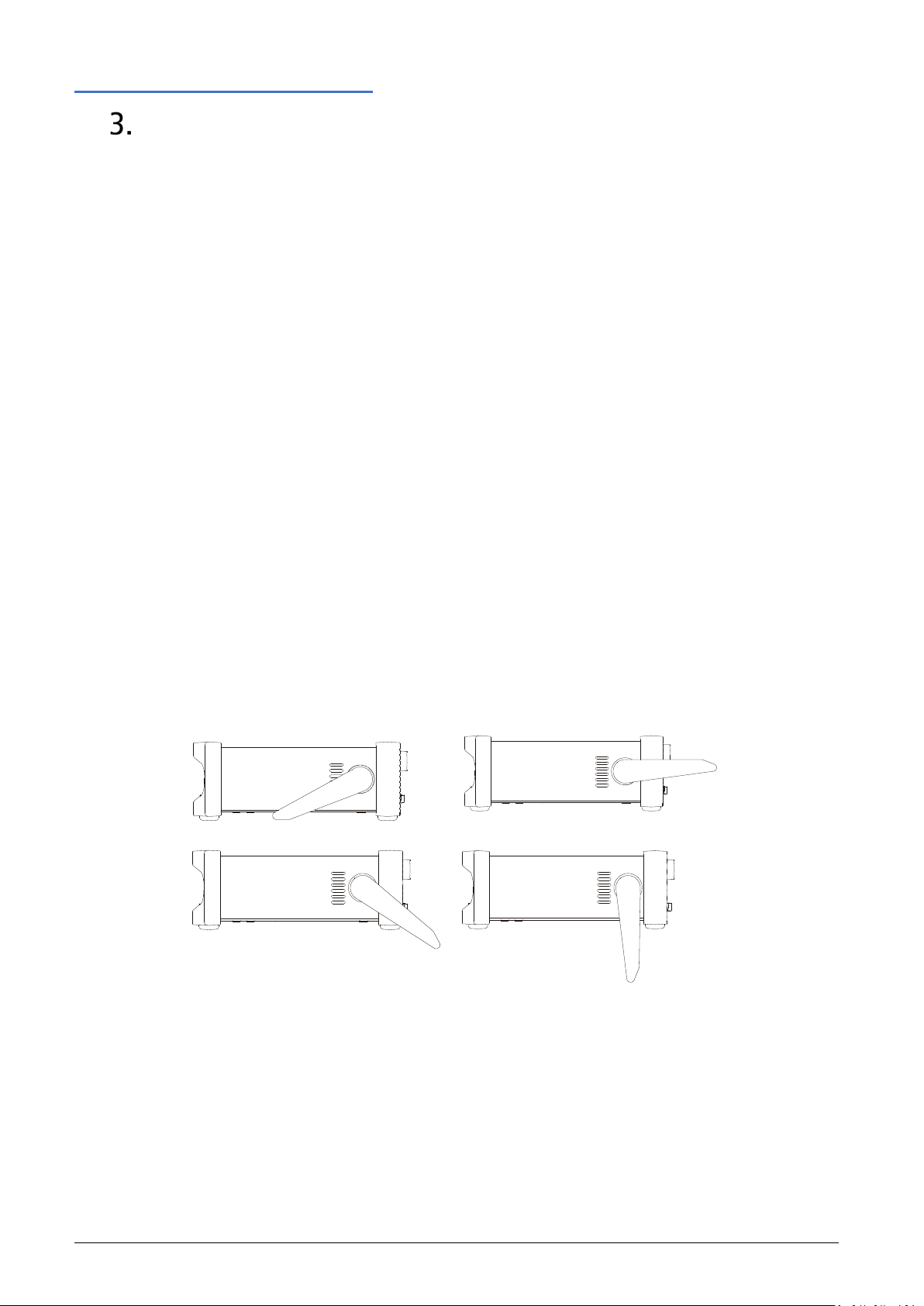
Handle/stand
The instrument is fitted with a 4-position handle/stand. Pull out both sides of the handle at the
case pivot points to free the position locking pegs and rotate the handle from the stowed
position to the required stand or handle position. Release the sides of the handle to lock it in
the new position.
7 SMU4000 Series Instruction Manual
Page 9

3 - Installation
A switch is located in the highlighted postiton (SW1).
Electrical Requirements
Electrical Requirements
Mains operating voltage
CAUTION
The operating voltage is switch selectable between 115Vac or 230Vac. You must check that the
local supply meets the AC input printed on the rear panel before connecting the unit to the
supply.
Changing the mains operating voltage
Should it be necessary to change the operating voltage from 230V to 115V or vice-versa, follow
the instructions below:
WARNING
The apparatus must be disconnected from all voltage sources before it is opened for any
adjustment. Capacitors inside the SMU may still be charged even if it has been disconnected
from all voltage sources, these will be safely discharged a few minutes after switching off. LEDs
on the HV rail to indicate that charge is still present, as such it’s not safe to dismantle until all
LEDs have gone out.
Remove the case:
① Position the handle as shown.
③ Slide and lift the case clear.
Mains supply voltage selection:
Select the required value with the switch
and replace the case.
CAUTION
② Remove 2x screws from the rear panel.
The set AC input voltage MUST be clearly
labeled on the rear panel.
8 SMU4000 Series Instruction Manual
Page 10
3 - Installation
Switching On
Mains lead
Connect the instrument to the AC supply using the mains lead provided.
Should a mains plug be required for a different mains outlet socket, a suitably rated and
approved 3 core mains lead with protective earth conductor should be used which is fitted with
the required wall plug and an IEC60320 C13 connector for the instrument end.
The minimum current rating of the lead-set for the intended AC supply is 6A or more.
WARNING
THIS INSTRUMENT MUST BE EARTHED.
Any interruption of the mains earth conductor inside or outside the instrument will make the
instrument dangerous. Intentional interruption is prohibited.
Before use, inspect provided mains lead for any signs of damage. Do not use if lead is damaged.
Before use, inspect the instrument for any signs of damage. Do not use if damaged.
WARNING
Switching On
Connect the instrument to the AC supply using the mains lead provided.
Press the standby button; the button will illuminate to indicate start up. At power-up the
instrument will display a start-up message whilst initialising the application.
Loading takes a short while as the SMU will carry out self-testing and a self-calibration (at every
power cycle), after which the home screen is displayed.
To sw itch off, press the standby button. When powered down into standby mode the LED is
dimly lit, indicating mains power is still present.
To fully disconnect from the AC supply, unplug the mains cord from the back of the instrument
or switch off at the AC supply outlet; make sure that the means of disconnection is readily
accessible. Disconnect from the AC supply when not in use.
9 SMU4000 Series Instruction Manual
Page 11

4 - Instrument overview
②
⑧
Front Panel
INSTRUMENT OVERVIEW
CAUTION
Front Panel
④
⑤
⑥
③
⑩
⑦
⑨
①
① Standby button
When pressed to power up the instrument, the button will illuminate to indicate start up.
When powered down into standby mode, mains power is still present.
Alternative power up options are available, see ‘Power Control’ for more details.
② Remote Indicator LEDs
When the instrument is being controlled remotely, the remote indicator will be illuminated,
either the LAN, USB or GPIB indicator will also be illuminated, depending on the communication
type.
③ Flash Drive
This is a USB Host port for the connection of flash drives which conform to the Mass Storage
Class specification and are formatted as FAT3 2.
Setups, sequences, and lists can be imported and exported via the flash drive port, see ‘Storing
and Loading Setup Files’ for more details.
Measurement data can be automatically recorded to the flash drive on completion of a test run,
see ‘Saving Data’ for more details.
Images of the display can be captured and exported using the flash drive port see ‘Icons/
indicators on the status bar’ for more details
④ Rotary Knob
The rotary knob is used to navigate the user interface and scroll through values - it features a
‘press’ function to select an option, see ‘
Basic operation’ for more details.
⑤ Menu Keys
- HOME - Returns to the home screen, see ‘Home screen’ for more details.
- CNFG- Accesses the main menu configuration screen
10 SMU4000 Series Instruction Manual
Page 12
4 - Instrument overview
Front Panel
⑥ Run Key
The Run key enables the output and executes the present configuration.
⑦ Test Key
The Test key performs a quick internal self-calibration and measurement zero. See ‘Zero
Calibration’ for more details.
⑧ Help Key
The context sensitive help key provides direct assistance with menus, settings, and parameters.
⑨ Terminals
The front input terminals are 4mm safety sockets on a 19mm pitch designed to accept 4mm
safety plugs with fixed or retractable shrouds.
WARNING
CAUTION
Only ever use either the front or rear terminals, never use both at once. Hazardous voltages
will appear on both sets of terminals.
SMU4201 Front and Rear Terminal Blocks, Main/ Force(F), Sense(S) and Guard(G) can be set
and operate at voltages up to 210Vpeak. Voltages greater than 60V are deemed hazardous
voltages.
Only use test leads conforming to IEC61010-031.
Always make connections to the instrument with the OUTPUT off and in the Open off state;
this is the only output state that completely isolates the external circuitry from the
instrument.
All terminals are rated to 300Vpeak with respect to earth ground. Safety will be maintained if
voltages up to 21Vpeak for SMU4001 or 210Vpeak for SMU4201, are accidentally applied
between inappropriate terminals in excess of their marked ratings. The maximum differential
between MAIN HI and SENSE HI and MAIN LO and SENSE LO should be < 2Vpeak. The SENSE
terminals are protected against accidental connection of up to 21Vpeak for SMU4001 or
210Vpeak for SMU4201 between HI & LO.
Main- Main Terminals source or sink voltage or current.
Sense- Sense terminals measure voltage. The HI Sense terminal can be used as a guard in 2 Wire
+ Guard setups. 4 Wire setups use the HI & LO Sense plus the HI & LO Main terminals.
Ground- chassis ground for ground reference purposes only. See ‘Terminal selection’ for more
details.
⑩ CV / CC LED indicator
When the output is running, the CV/ CC indicators show whether the instrument is in Constant
Voltage or Constant Current.
11 SMU4000 Series Instruction Manual
Page 13

4 - Instrument overview
②
③
Rear Panel
Rear Panel
④
WARNING
①
⑤
⑥
⑦
⑧
① Terminal Block
The terminal block provides rear access to the Main and Sense connections with the addition of
Guard connections.
To connect a wire, press the orange actuators of the screwless terminals, insert the connecting
wire and release the actuator to secure the connection.
Use insulated wire (solid or stranded, 0.5mm2 to 1.5mm2 (21 to 16AWG), strip length 9mm to
10mm) suitable to meet local safety standard for 300Vpeak, i.e. tri-rated 600V equipment wire
with uninsulated ferrule. Ensure there are no loose strands.
Only ever use either the front or rear terminals, never use both at once. Hazardous voltages
will appear on both sets of terminals.
CAUTION
SMU4201 Front and Rear Terminal Blocks, Main/ Force(F), Sense(S) and Guard(G) can be set
and operate at voltages up to 210Vpeak Voltages greater than 60V are deemed hazardous
voltages.
Only use test leads conforming to IEC61010-031.
Always make connections to the instrument with the OUTPUT off and in the Open off state;
this is the only output state that completely isolates the external circuitry from the
instrument.
All terminals are rated to 300Vpeak with respect to earth ground. Safety will be maintained if
voltages up to 21Vpeak for SMU4001 or 210Vpeak for SMU4201, are accidentally applied
between inappropriate terminals in excess of their marked ratings. The maximum differential
between FORCE HI and SENSE HI and FORCE LO and SENSE LO should be < 2Vpeak. The SENSE
terminals are protected against accidental connection of up to 21Vpeak for SMU4001 or
210Vpeak for SMU4201 between HI & LO.
F +/- [Force] - Force terminals source or sink voltage or current, they are permanently wired in
parallel with the front panel Main HI and LO terminals.
12 SMU4000 Series Instruction Manual
Page 14

4 - Instrument overview
Rear Panel
S +/- [Sense]- Sense terminals measure voltage and are permanently wired in parallel with the
front panel SENSE HI and LO terminals. 4 Wire setups use the HI & LO Sense plus the HI & LO
FORCE terminals.
WARNING
G [Guard] terminals
Dedicated Guard terminals only feature on the rear panel.
The Guard signal driven to the same potential as the FORCE HI. As such, if the FORCE HI is at a
hazardous voltage, the same hazardous voltage level will also be present at the Guard.
See ‘Terminal selection’ for more details.
② AC power inlet
The instrument must be connected to AC mains using the power lead provided. When the
power lead is connected this lead provides the necessary protective earth connection to an
external protective earth system. See ‘Electrical Requirements’ for more details.
③GPIB (optional)
For GPIB connection the SMU Requires a GPIB 1A user retrofittable option, available from the
manufacturers or their agents. The default GPIB address is 10. See ‘Remote interfaces’ for more
details.
④ USB
The USB device port accepts a standard USB cable. The Windows plug-and-play functions should
automatically recognise that the instrument has been connected. See ‘Remote interfaces’ for
more details.
⑤ K Lock
The Kensington slot is a standard slot that can be paired with a security cable lock.
⑥ LAN
The LAN interface is designed to meet 1.5 LXI (LAN extensions for Instrumentation) Core
2016.Remote control using the LAN interface is possible using a TCP/IP Socket protocol. See
‘Remote interfaces’ for more details.
⑦ Chassis earth M4
The M4 threaded screw marked provides a connection point to safety earth ground. An M4 Ring
tab must be used, with an appropriate washer.
⑧ Digital I/O [DIO]
The DIO is an input/output port that receives, and outputs signals through digital I/O lines. See
‘Digital I/O’ for more details.
+5.25Vpk Max. (diode clamped to +5V). The 5V supply is internally fused (resettable fuse) to
500mA, see the SMU4000 Series Service Manual for more information.
13 SMU4000 Series Instruction Manual
Page 15

5 - Introduction
Using this Manual
INTRODUCTION
Using this Manual
This manual is a general introduction to the organisation of the instrument and is intended to be
read before using the instrument for the first time.
In this manual:
The descriptions in this manual relate to using the instrument via the touch screen,
alternatively; the hard keys and rotary knob can be used. See Navigation Controls for details on
how to use the rotary knob to control the instrument.
Throughout this manual, the navigation through menus will be shown at the top of a section
using the following format: MENU>Sub Menu>Option
· Front panel keys and sockets are shown in capitals, e.g., HOME, CNFG;
· Text, entry fields and messages displayed on the LCD are shown in a different
font, e.g., Source, Limit, Results.
· Hyperlinks are shown in italics, e.g., ‘Using this Manual’
Other Manuals are available to download for this product series including:
· Safety Documentation and Quick Start Guide [English, French, German, Italian
& Spanish]
· Programming Manual [English]
· Service Guide [English] available on request.
Available from www.aimtti.com/support.
14 SMU4000 Series Instruction Manual
Page 16

5 - Introduction
Navigation Controls
Navigation Controls
Hard Keys
There are two main menus: HOME and CNFG (configuration)- These are accessed using the hard
keys on the front panel. The items within these menus can be selected using the following
options:
· Touch Screen
Direct selection and entry using touch. Simply touch the item with your finger
to select.
· Rotary Knob
Turn the knob clockwise to initiate, once the desired button has been selected,
press to engage the button. The knob can also be used to modify home screen
parameters once they have been selected.
Menu Scrolling
Some menus contain more than one page of options, when this is the case, arrows ① are
available to scroll the page up or down.
OK / Cancel
The OK and Cancel ② keys are available on all screens where changes can be made; pressing
OK will apply any changes and return the previous menu., Cancel will return to the previous
screen without making any changes.
②
①
Back Button
The Back button is available on sub menus, when pressed it will return to the previous menu.
15 SMU4000 Series Instruction Manual
Page 17

5 - Introduction
①
② ③ ④
Navigation Controls
Numeric Keypad / Keyboard Pop-up
Depending on where the keypad pop-up appears, the following options will be available to
select from on the keypad.
① Non-numeric Options:
Auto / Disabled etc.
② Numeric Selection
Numeric selection is 0-9, decimal point and minus sign (if negative values can be entered)
③ Unit Selection
④ Actions:
Bksp- Remove the previous number.
Revert- Revert the value back to the original; before the value was amended with the keypad.
Rev Pol- Available when a positive or negative value is to be accepted, toggles between plus
and minus symbol.
A full QWERTY keyboard is available for text entry.
16 SMU4000 Series Instruction Manual
Page 18

5 - Introduction
Home screen
Home screen
①
②
③
① Status bar
• USB flash drive status (connected/disconnected) and touch to capture screen image, if
connected.
④
• Logged Event; a Warning, Caution or Information pop up has occurred and been logged.
Touch to see the Event Log.
• LAN Status. Touch to edit in the Interfaces menu.
• Present Mode and selected shape (if other than steady), Output status, terminal
configuration and selected OFF state. See ‘Icons’ for more details. Touch to edit in the
Manual Setup menu.
• Operating voltage limit [SMU4201 only]. LV (low voltage mode) for up to ±42V working
mode, HV (high voltage mode) for up to ±210V working mode. Touch to change
between LV and HV. By default, the unit is locked into LV mode and password protected,
see ‘Password protection’ for more details.
• Date and time, touch to edit, see ‘Date and Time’ for more details.
② Source and Limits
User defined source/sink level and imposed limits, depending upon the selected mode.
Values can be modified by direct touch keypad entry, simply press on the relevant
parameter to bring up the numeric entry screen. Alternatively, the selected values can
be modified by using the rotary knob.
③ Results
Results box contains the real time measurements and, if enabled, the measurement
reference and math formula applied to the readings. When in Sequence mode the
active step and operating mode will be shown.
④ Buttons:
See ‘Measurement selection, ’Selecting a Range’, ‘Graph view Menu’ or ‘Sample table’
for more information.
17 SMU4000 Series Instruction Manual
Page 19

5 - Introduction
Icon
Variations
Description
Not Connected
Reading
USB Connected, Press to capture screen image
USB not supported.
③
Event log
LAN
LAN detected
↑↓
Data Transfer detected
LAN IP Error
LAN IP Address Error
Press to edit the setup.
SV
Source Voltage
SC
Source Current
LC
Load Current
LR
Load Resistance
LP
Load Power
MV
Measure Voltage
MC
Measure Current
MR
Measure Resistance- Voltage Limited
MHR
Measure Resistance- Current Limited
SEQ
Sequence Mode
Note: If Sequence Mode is running it will show the Active Mode in the step.
OFF
Output Off
ON
Output On
CC
Output On - Constant Current
CV
Output On - Constant Voltage
CMV
Output On- Constant Maximum Voltage
2 Wire
Main terminals- Source and Sense
2W+Guard
Main terminals- Source and Sense. HI Sense terminal - Guard
4 Wire
Main terminals- Source and Sense. Sense Terminals- Sense
0V/100µA
Source 0V/ 100uA current limit
Hi Z
Terminals are high impedance
Zero
Source 0V
Open
Terminals are open circuit
Steady
Source is steady
Pulse
Source is pulsed between two levels
Sweep
Source is swept in steps between start and end levels
List
Source is defined by a custom list of levels
Pulsed sweep
Source is swept in pulsed steps between start and end levels.
⑤
Press to activate/deactivate the High Voltage Interlock. Note: To access the High Voltage
*SMU4201
LV
Low Voltage Mode
HV
High Voltage Mode.
⑥Time
and Date
①
④
②
③
⑤
⑥
Home screen
Icons/ indicators on the status bar
The following icons or indicators may appear on the status bar.
①
USB Flash
Drive
②
LAN
status
④
Setup
Status
Active Mode
Output
status
Event logged, Press to see logged event/s
Press to edit Interface setup
Terminal
configuration
Off State
(Output Off)
Shape
(Output On,
in place of
Off State)
Operating
Voltage
Limit *
Interlock, the password protection may need to be removed first.
only.
Press to edit Time and Date
18 SMU4000 Series Instruction Manual
Page 20

6 - Getting Started
Connections
GETTING STARTED
Connections
Connections can be made to the front or rear terminals on the instrument. The front and rear
terminals are connected in parallel and must never be used simultaneously.
Front/Rear connections
Front and rear terminals are always active, there is no need to select between the two.
The terminals on the front panel are 4mm banana jack connectors, and the rear-panel contains
a terminal block. The rear terminals offer additional Guard connections for screening, see
‘Terminal selection’ for more details.
Front panel Main HI and LO terminals are permanently wired in parallel with the rear panel F +/[Force] terminals.
Front panel SENSE HI and LO terminals are permanently wired in parallel with the rear panel S
+/- [Sense] terminals
WARNING
Only ever use either the front or rear terminals, never use both at once. Hazardous voltages
will appear on both sets of terminals.
Hazardous voltages will appear on both sets of terminals.
Always make connections to the instrument with the OUTPUT off and in the Open off state;
this is the only output state that completely isolates the external circuitry from the
instrument.
19 SMU4000 Series Instruction Manual
Page 21

6 - Getting Started
High Voltage Interlock [SMU4201 only]
High Voltage Interlock [SMU4201 only]
The instrument contains a high voltage interlock to prevent accidental access to potentially
dangerous high voltages.
By default, the instrument is set to Low Voltage operation, restricting the maximum permitted
voltage to ±42V DC. Source level and limit settings are restricted to a maximum of ±42V DC. If
for whatever reason this voltage limit is exceeded whilst the output is running, the output will
either continue to run and limit the voltage to the maximum of ±42V DC (Limited), or the
output will trip to the OPEN off state condition (Trip). This feature can be set in the Interlock
Behaviour menu:
CNFG > [System] Manage > [Security] Interlock Behaviour.
The status of the interlock is shown in the form of a HV/LV icon on the status bar of the user
interface home screen and can also be queried remo tely.
There are three ways in which the interlock state can be changed between Low voltage
operation and full voltage operation:
1. Password Protection: A password entry is required to enable full voltage operation. See
‘
Password protection’. Once the password is entered correctly the interlock status can be
changed by touching the LV symbol on the status bar of the home screen.
WARNING
2. External DIO control: This allows for the controlling of the interlock via external circuitry.
This is primarily designed for helping to ensure the safe operation and safety of users of the
equipment when embedded into a test system or test fixture. For safety reasons, test
fixtures that may contain hazardous voltages often utilize a safety cover, a form of lid or
even complete doors to protect the user from hazardous voltage exposure. Installing a
switch on any of these and linking to the external DIO interlock control allows for the
limiting of hazardous voltages (Low voltage operation) whenever the switch is opened. For
more information on the DIO interlock control see ‘
Digital I/O’.
3. Remote interface control: The state of the interlock can be controlled directly without
password protection. The status of the interlock can also be queried remotel y. See the
SMU4000 Series Programming Manual for more information.
Enabling full voltage operation (asserting the interlock) could expose the user to potentially
hazardous voltages that could result in injury or death.
Potentially hazardous voltages of up to ±210 V may be present at the MAIN HI, F+/-, Sense HI,
S+/- and Guard terminals.
These terminals should be considered hazardous even if set to a non-hazardous voltage or
current level.
NOTE
Whenever the interlock setting is changed via the front panel or remote command, the output
is disabled for safety purposes.
20 SMU4000 Series Instruction Manual
Page 22

6 - Getting Started
Basic operation
Basic operation
Sourcing voltage and recording measurements
When set to default settings, the source voltage configuration settings will be loaded. To set the
source level:
· Touch the source setting.
· Enter the required value and press OK.
· Press the RUN hard key to activate the output.
The default measurement count is infinite; therefore, measurements will be recorded up to the
maximum amount of 100,000. Once reached, the output will remain on but measurements will
no longer be recorded.
The default measurement period is 1 PLC. One Power Line Cycle (PLC) for 50Hz is 20ms and one
PLC for 60Hz is 16.67ms. Mains input frequency is automatically monitored and applied by the
instrument.
21 SMU4000 Series Instruction Manual
Page 23

6 - Getting Started
Basic operation
Live adjusting source and limits from the home screen
The source and limit parameters can be adjusted in real time using the rotary knob when the
output is active. To adjust the source level in real time:
· Press the RUN hard key to activate the output.
· Highlight the source value using the rotary knob.
· Press the knob to enter the editing state, the knob will now scroll through the
source values.
NOTE
· Scrolling left and right will change the value resolution. Press again to edit the
numeric value.
A green digit indicates the encoder is in an active state, any adjustments using the encoder are
live and will be actioned at the terminals immediately (when the SMU is running).
· Double press the knob or press the HOME key to exit the live editing mode.
22 SMU4000 Series Instruction Manual
Page 24

6 - Getting Started
Selecting a Range
Selecting a Range
HOME > Ranges
Before considering a range selection it is important to understand the concept of manual setup
modes that are used in the SMU; see ‘Operating Mode’ for more details. Configuration settings,
including the selected ranges, are linked to the selected mode of operation.
NOTE
Range selection is ‘Manual setup’ specific.
Ranges can be set for current and voltage, the available ranges are determined by the selected
mode of operation.
A range can be set to Auto, or a manual value.
Most applications will require Auto Range, however if high accuracy or speed is required it may
be necessary to select a manual range.
The automatic range selection determines and selects the most suitable ranges based upon the
measured readings and source settings.
Timing considerations
Faster Response Speeds
Selecting a manual range can assist with faster response speed. Auto ranging changes the range
whilst the output is running, this can lead to increased rise/measurement/settling times whilst
the instrument selects the appropriate range; selecting a manual range overcomes this potential
timing penalty.
NOTE
The fastest response speeds can only be achieved when a manual range is selected.
Reduced settling times
Settling times can be reduced when in auto range by selecting a minimum range value. This
defines the minimum range that the instrument can select during auto-ranging. Setting this to
the lowest range that is required for the given test/application may help to reduce the settling
time, as the lower ranges have generally longer settling times.
23 SMU4000 Series Instruction Manual
Page 25

6 - Getting Started
Selecting a Range
In order to bypass this functionality, simply set the minimum range to the smallest range
available.
To set the minimum range, press the Auto (Min.Range xxx) Button. Set the minimum required
range and press Back to return to the Range Menu.
Stability Considerations
NOTE
NOTE
Auto ranging can, in some specific cases (where there may be a significantly highly reactive load)
lead to potential instability or oscillations. If this occurs, selecting the appropriate manual ranges
can alleviate the issue. When using the most sensitive current ranges i.e.200nA and 2µA ranges
potentially instability could occur, in this case try a higher current range.
Limit considerations
The source and limit level settings cannot exceed 105% of the selected associated range. The
limit setting is restricted to a minimum of 10% of the manually selected range.
If a lower manual range is selected that causes the existing source or limit level setting to exceed
the selected range maximum, the associated level is set to 105% of the new range. Likewise, if a
higher manual range is selected that causes the existing limit level setting to exceed the selected
range maximum, the limit level is set to 10% of the new range.
In SC and MR modes (see ‘Operating Mode’ for more details) where the current source is
utilized, the 3A range can only be accessed via manual range selection, the auto current range
will stop at the 1A range.
Noise pickup, leakage and instability issues may arise when testing within certain manual
ranges, see ‘Application notes’ for tips to overcome these issues.
24 SMU4000 Series Instruction Manual
Page 26
6 - Getting Started
Measurement selection
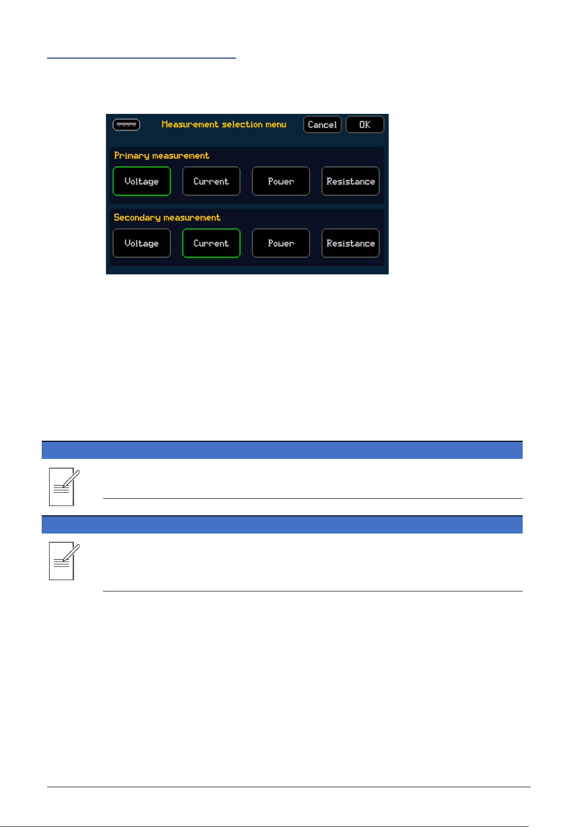
Measurement selection
HOME > Measure
The measurement selection configures the primary and secondary measurements. The primary
and secondary measurements can be set to measured voltage, measured current or the
computed power or resistance.
Only the selected primary and secondary measurements appear on the home screen results
section, within the sample table measurement buffer and within the measurement statistics
menu.
The primary measurement is used for setting the live and custom measurement reference math
operations (See ‘Math’), and defining the measurement that is displayed on the YT graphical
view (See ‘Graph’).
NOTE
The exported .CSV files contain all four measurement types.
NOTE
Alternative primary and secondary measurement types can be selected after the test is
complete. The selected measurement data can be viewed in the sample table or the YT graph
(primary measurements).
25 SMU4000 Series Instruction Manual
Page 27

6 - Getting Started
Saving Data
Saving Data
CNFG > [Files] Data Store
The buffer records all the information displayed in the sample table. Up to 100,000 points can
be recorded at any time.
NOTE
The buffer data is cleared each time the output is run, ready for the next set of measurement
data to be collected. The buffer data is also automatically cleared when the instrument is power
cycled.
Buffered data can be saved as a .CSV file to a USB flash drive connected via the front panel,
either manually or automatically.
The .CSV file will contain the following information:
· Index
· Active Mode
· Output state
· Measurement results (V and A)
· Calculated results (R and W)
· System Date
· System Time
· Measurement Timestamp
· Sequence Mode Step and Iteration
NOTE
To store all measurement data, the measurement buffer should be exported over remote or to
an external flash drive after completion of each run (automatically).
26 SMU4000 Series Instruction Manual
Page 28

6 - Getting Started
Saving Data
Save Data Automatically
To automatically save the data to USB after every run, press the Auto Store function. The file
name will be highlighted with a green border and the data will be saved to the flash drive when
the SMU has completed a run.
Save Data Manually
To manually save data, press the USB Store button. A .CSV file will be saved to the USB Flash
drive each time the USB Store button is pressed.
Buffer status
The buffer status is displayed as a percentage within the Clear button, when pressed the data
will be cleared and set to 0%.
View buffer data
Buffered Data can be viewed in three different formats from the front panel:
· Individually indexed measurements, see ‘Sample table’ for more details.
· Graphically plotted data, see ‘Graph’ for more details.
· Statistically, see ‘Measure Statistics’ for more details.
27 SMU4000 Series Instruction Manual
Page 29

6 - Getting Started
Sample table
Sample table
CNFG > [Files] Sample Table
The Sample Table displays the contents of the buffered measurement data in a table format. The
contents of the table include the index, primary measurement, secondary measurement, date,
and time. Results are stored sequentially from the first index number and will be stored until the
buffer limit is reached, at 100,000 measurements.
The time is recorded as HH:MM: SS.
The date is recorded as DD/MM/YYYY (Default), MM/DD/YYYY or YYYY/MM/DD, depending on
the format selected, see ‘Date and Time’ for more details .
All exported data from the sample table to the .csv file will be formatted as YYYY/MM/DD.
The up and down arrow keys can be used to scroll through the results in the sample table. Using
the touch screen, pressing, and holding the button will scroll through the results faster.
A single result can be selected and used as a reference point for a math function. To set the
reference point, use the encoder to select the required primary measurement and press to
activate. See ‘Math’ for more details.
NOTE
The sample table will only display the primary and secondary measurement data; however, the
internal buffer contains all four measurements which can be exported or can be accessed via
changing the primary and secondary measurements. Changing the primary and secondary
measurements can be done live or even after the test is complete to access all four
measurement data sets.
28 SMU4000 Series Instruction Manual
Page 30
6 - Getting Started
Measurement Statistics
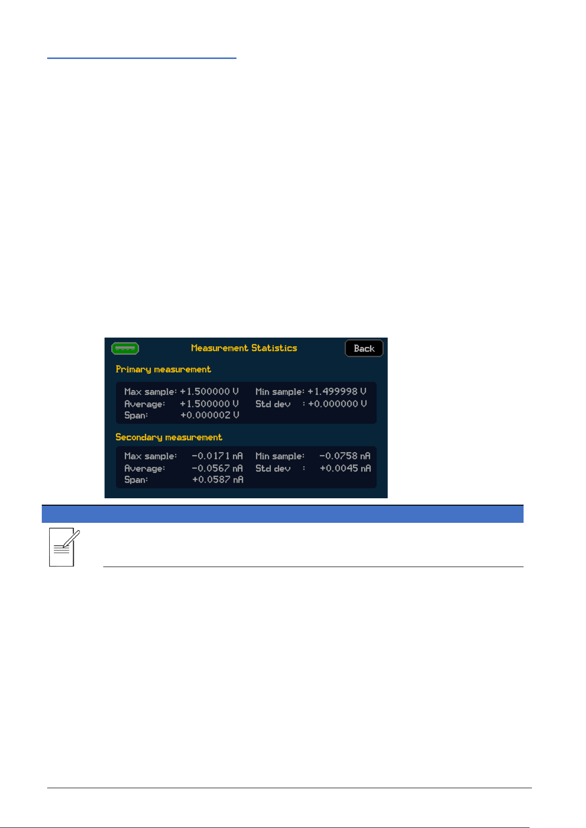
Measurement Statistics
CNFG > [Files] Measure Statistics
The measurement statistics menu provides statistical measurement information based upon the
primary and secondary measurement data. With a large 100k measurement buffer it can be
very difficult to pick out key information from the sample table alone. The measurement
statistics menu provides details of:
· Minimum sample value
· Maximum sample value
· Total measurement span (min to max)
· Average (mean)
· Standard deviation of the measurements for both the primary and secondary
measurements.
The measurement statistical data is based on the data that is in the sample table and is updated
accordingly, as new data is recorded.
NOTE
Changes to the primary and secondary measurements can be actioned live or even after the test
is complete to access all four sets of measurement statical data (V, I, W & Ω).
29 SMU4000 Series Instruction Manual
Page 31

6 - Getting Started
Feature
Graph
Graph View
Graph
Graph
The Graph provides a graphical representation of the buffered results. This may be real time
data or previous test data already stored in the buffer. The real time / buffered data is always
shown in yellow. Any saved ‘Tra c e’ data is shown in blue- see ‘Trace’ for more details.
There are two separate graphing menus; graphing options with full manual control that is
accessed from the Configuration (CNFG) menu, and a view of the graph that is accessed from
the home screen.
NOTE
The two graph menus are linked; changes made in the Graph menu will be reflected in Graph
view and vice-versa.
(Blue background)
CNFG > [Files] Graph
(Black Background)
HOME > Graph View
Auto-Scale •
Auto-Fit •
Graph Type • •
Graph Style • •
Minimum Position • •
Markers • •
Save/Load Trace • •
Panning •
Zooming •
30 SMU4000 Series Instruction Manual
Page 32

6 - Getting Started
Graph Menu
Graph Menu
The graph uses an Auto-Scaling function to best fit the data onto the graph, the difference
between the Auto-Scaling and the Auto-Fit of the Graph View is that the Auto-Scaling is
designed like a traditional oscilloscope with standard 1,2,5 scaling applied to the X and Y axis.
Auto-Scaling also applies no offset compensation.
Auto -Scaling is activated by pressing a Graph Type button ①
Graph Type
Measurement data can be displayed in two formats, as two different graph types:
YT Graph (Default): The primary measurement data is plotted against time on the X axis.
①
NOTE
Voltammogram (I/V Scatter): A plot of voltage against current. This graph type is ideal for I/V
curve tracing.
Select the graph type using the Voltammogram and YT Graph buttons positioned above the
graph display.
Pressing either the Voltammogram or YT Graph buttons will cause the graph to auto-scale; any
manual scaling changes will be lost.
31 SMU4000 Series Instruction Manual
Page 33

6 - Getting Started
Graph Menu
Graph Settings
The following settings are available by pressing the Settings button:
Graph Style
Line (Default): Show the measured points connected in a linear format with a single line.
Point: Show each measured point on the graph as a single pixel.
Minimum position
A minimum X and Y position can be defined, starting the plotted results at a defined point.
32 SMU4000 Series Instruction Manual
Page 34

6 - Getting Started
Not Active (Default)
Active and Selected
Active, not Selected
Graph Menu
Markers
Markers are based on the display position and are not linked to measurement data points.
Marker selection is a multi-stage process:
To enable the markers, select the Marker 1 or Marker 2 button located at the bottom of the
graph.
Upon the first press the marker will appear as a red line across the span of the graph and a
green outline will appear to show the marker can now be moved, use the encoder to move the
marker.
The Marker Button shows the marker value, which is shown to a resolution of up to four digits,
to see the full resolution of the marker reference point, use the Stats button.
Once a marker has been selected, the markers menu ① will be active.
①
Marker orientation can be set to horizontal using the H.pos button or vertical using the V.p os
Button. When both X and Y markers are set to the same orientation, the difference between the
two is displayed in the bottom right-hand corner of the display in the marker’s menu. To see the
full resolution, use the Stats button.
33 SMU4000 Series Instruction Manual
A reference point based on the selected marker (used in the math function) can be set directly
from the graph using the Set Ref button. See ‘Math’ for more details.
Pressing the Marker button whilst the marker is active will disable the movement of the marker
via the encoder; however, the marker value and marker menu will still be displayed. This allows
for selection switching between the two markers, only one marker position can be adjusted at
any given time.
Page 35

6 - Getting Started
Graph Menu
A final consecutive press of the marker button disables the marker completely, the marker menu
will still be displayed if the either marker is still active.
Trace
The trace functionality enables a reference trace to be stored and recalled, allowing for a
previously stored trace to be compared against the latest measurement trace. Data in the buffer
will be displayed in yellow, the trace will be blue.
Once Trace has been selected, the trace menu ① will be active.
①
NOTE
This can be very useful when comparing two DUTs (device under test) to see the difference in
performance between the two. One reference trace can be stored at any given time.
The trace menu gives the following options –
Save – Store the existing latest measurement graphical waveform as the reference trace.
Load – Recall and display the previously saved reference trace.
Disable – Stop viewing the loaded reference trace.
The loaded reference trace appears in blue on the same graph as the latest measurement trace.
NOTE
When recalling a trace, the graph auto-scale will ensure both the recalled trace and the latest
measurement trace are visible on the display regardless of difference in levels.
34 SMU4000 Series Instruction Manual
Page 36

6 - Getting Started
Graph Menu
X & Y Axis Scaling
The X and Y Axis scale can be altered to effectively ‘zoom’ in or out of the displayed data on the
graph – this method will force the scaling into manual mode.
To change the scale, select the X (xxx/div) or Y (xxx/div) button located at the bottom of the
graph. The X and Y axis will remain in the automatically selected ranges until modified. A green
outline will appear to show the range can now be changed, use the encoder to change the
range, the scale will then be adjusted using units per division.
Press the button again to disable the movement via encoder and return to navigation.
NOTE
To familiarise a new user with the graph navigation; using the Auto-Scale (Type button) to define
the best suited ranges for the data, then using the manual scale to ‘zoom’ in and out on specific
areas of the measurement data by increasing and decreasing the scale as needed.
Panning
Panning can be set to horizontal using the H.Pan button or vertical using the V.Pan button
located in the Main menu section of the graph, this function will force the scaling into manual
mode. Once selected a green outline will appear to show that the graph can now be moved
either vertically or horizontally (dependant on selection). Use the encoder to pan the graph.
Press the button again to disable the movement via encoder and return to navigation.
35 SMU4000 Series Instruction Manual
Page 37

6 - Getting Started
Graph view Menu
Graph view Menu
HOME > Graph View
Graph View uses Auto-fit scaling- displaying the results in an automatically scaled view to best fit
the display; all the results will be shown at once. Graph view utilizes no standard range scaling,
the scaling is entirely arbitrary, allowing the results to fill the graphical area. The auto-fit scaling
also deals with any offsets within the measurement data, offsetting the graphical view
accordingly. This provides an instant graphical view of all the buffered measurement data, scaled
to fit perfectly within the graphical window area. The Graph View menu has a darker (black)
background than the Graph menu, to assist with recognition.
NOTE
Scaling or panning functions are not available in Graph Vie w.
Although scaling or panning options are not available, one method that can be implemented for
focusing in on an area of interest can be to re-run a specific test within the window of interest.
Graph view allows for the quick and easy view of the full measurement buffer data, which
means that a specific area of interest is very easy to find, especially with the use of the markers.
As an example, re-running an I/V trace curve sweep of a DUT around the area of interest can be
potentially quicker and provide greater measurement resolution than trying to pan and zoom
into a specific area of a graph under manual control.
The Graph View menu allows the use of Markers and the reference Trace function to view,
assess, and compare the results. The graph type can be set to
graph style to
Point or Line see ‘Graph Menu’ for more details on these functions.
NOTE
When a USB Flash Drive is present, screen captures of the graph can be stored by pressing the
flash Drive symbol in the top left corner.
YT Graph or Voltammogram, and
36 SMU4000 Series Instruction Manual
Page 38

6 - Getting Started
①
②
Storing and Loading Setup Files
Storing and Loading Setup Files
CNFG > [Source Measure Action] Store Setup
Setup Files are managed in the Store Setup menu, from here Setups can be:
· Stored to an Internal Memory.
· Recalled from the Internal Memory.
· Deleted from the Internal Memory.
· Exported to a USB Flash Drive.
· Imported from a USB Flash Drive.
Store a Setup to the Internal Memory
To store a Setup to the Internal Memory, select the item Empty block ① followed by Store
Internal ②. A keyboard will appear on screen, type the required file name- up to 7 characters,
and press OK.
NOTE
The file type will vary depending on the set mode, there are two types of files that will be
stored:
.STP – Manual Setup file type
.STP files contain all the set parameters from the Manual Setup when one of the following
Manual Modes are selected: SV, SC, LC, LR, LP, MV, MC, MR, or MHR.
.STP files stored in the internal memory can be added to a Sequence. See ‘Sequence mode’ for
more details.
.SEQ - Sequenced Setup file type
.SEQ files contain the contents of the sequence setup when ‘Sequence’ is the selected Manual
Mode.
Up to 20 manual setup files and 20 sequenced setup files can be stored at one time between
the internal memory and USB flash drive.
The files stored on the Internal memory will take priority. If a USB flash drive is connected and
internal max file limit is reached, no external files will be shown until an internal file is deleted.
37 SMU4000 Series Instruction Manual
Page 39

6 - Getting Started
①
②
③
Storing and Loading Setup Files
Load a Setup from the Internal Memory
To recall a Setup from the Internal Memory, select the required setup ①, followed by Load ②.
A pop-up box will appear to confirm the action.
NOTE
Recalling any stored setup will overwrite the existing configuration.
④
Delete a Setup from the Internal Memory
To delete a Setup from the Internal Memory, select the required setup ①, followed by Delete
④. A pop-up box will appear requesting to confirm the action.
Export a file to a USB Flash Drive
Once a setup has been stored as an internal file, it can be exported to a USB Flash Drive.
To export a file, select the file to be transferred ①, once selected the file name will be
highlighted with a green border, press Store USB to export.
The file will appear in the available setups list, with USB as the location.
38 SMU4000 Series Instruction Manual
Page 40

6 - Getting Started
②
①
Storing and Loading Setup Files
Import a file from a USB Flash Drive
USB files can be imported into the Internal Memory.
NOTE
Files must be imported into the Internal Memory before they can be loaded, external USB Files
cannot be loaded or deleted using the store setup menu.
To import a file, select the file ① to be imported, once selected the file name will be
surrounded with a green box, press Store Internal ② to import.
The file will appear in the available setups list, with Internal as the location.
File type- colour
File names may appear in the following colours:
Yellow: Compatible.
White: Incompatible with the current firmware version or model.
Red: Corrupted- Unable to be used or recovered.
To load an arbitrary list of set levels for a sweep (.CSV), see ‘Loading a List’.
To store buffer measurements (.CSV), see ‘Saving Data ’.
39 SMU4000 Series Instruction Manual
Page 41

6 - Getting Started
Event log
Event log
CNFG > [System] Event Log
The Event Log displays a record of events that have occurred whilst the instrument has been
operational, these include warning, er ro r, and information alerts.
Whenever a new warning, error or information event occurs, a warning symbol
appears on the status line of the home screen, this is often accompanied by a pop-up.
Pop-ups are colour coded based on the type of event that has occurred.
The duration that the pop-up is displayed can be changed using the Message Time button; this
can be set to a duration in seconds, or infinite. When set to infinite, touch the pop-up to remove
it.
Selecting the Event Log symbol on the status bar will open the event log menu, this menu can
also be accessed through the System menu: CNFG > [System] Event Log. Within the Event log
menu, the events are colour coded and include a Warning or Error number alongside the time
and date of when the error occurred.
40 SMU4000 Series Instruction Manual
Page 42

7 - Easy setup
Easy setup
Manual Mode
Easy setup
Manual Mode
Power Supply
SV
Ammeter
MC
Current Source
SC
Ohmmeter
MR
Load
LC
LC Meter
SV
Voltmeter
MV
IR Meter
MHR
Overview
EASY SETUP
Overview
CNFG > [Source Measure Action] Easy Setup
The Easy Setup menu contains a number of pre-configured setups, providing instant
configuration for basic operational use of the SMU, these include:
· Power Supply
· Current Source
· Load
· Voltmeter
· Ammeter
NOTE
· Ohmmeter
· IR Meter [Insulation Resistance Meter ]
· LC Meter [Leakage Current Meter]
Selecting any of the pre-configured ‘Easy Setups’ will reset the settings to the default for the
related manual setup mode. However, if the manual setup is set to anything other than the
mode related to the easy set, the settings will still be available when returning to that mode.
See ‘Factory Default settings’ for more details.
Once an easy setup has been selected, further settings can be configured using the Manual
Setup menu.
To activate a pre-configured setup, select the required option and press OK. If no option is
selected, pressing OK will return to the Configuration menu and no change will be made.
For more details, see SMU4000 Series Safety Documentation and Quick Start Guide, available to
download from: www.aimtti.com/support.
41 SMU4000 Series Instruction Manual
Page 43

8 - Manual setup
Overview
MANUAL SETUP
Overview
CNFG > [Source Measure Action] Manual Setup
The Manual Setup menu contains options and settings for source and measurement
configurations.
NOTE
All options and settings in the Manual Setup menu are saved to the selected source and
measurement mode , or ‘Operating Mode’.
Manual Setup options and settings are as follows:
· ‘Operating Mode’ (Source / Load / Measurement/ Sequenced Mode)
· ‘Terminal selection’
· ‘Measurement count’
· ‘Source shape’
· ‘Output off state’
· ‘Source Level’
· ‘Limits and Protection’
· ‘Timing options’
· ‘Result sorting’
· ‘Math Functions’
When the manual setup is complete, it can be stored in non-volatile memory or exported via a
USB Flash Drive using the Store Setup menu, see ‘Storing and Loading Setup’ for more details.
42 SMU4000 Series Instruction Manual
Page 44

8 - Manual setup
Operating Mode
Operating Mode
CNFG > [Source Measure Action] Manual Setup > [Overall] Mode
The Mode menu contains options for the source and measurement operating functionality.
NOTE
All options and settings in the Manual Setup menu are saved to the selected ‘Operating Mode’.
Operating Mode options are as follows:
· ‘Source Voltage' [Default]
· ‘Source Current’
· ‘Load Current’
· ‘Load Resistance'
· ‘Load Power'
· ‘Measure Voltage’
· ‘Measure Current’
· ‘Measure Resistance and High Resistance’
NOTE
· ‘Sequence mode’
Changing the mode whilst the instrument output is running will disable the output to the given
Off State defined for that mode.
43 SMU4000 Series Instruction Manual
Page 45

8 - Manual setup
Source Modes
Source Modes
Source Voltage (SV)
CNFG > [Source Measure Action] Manual Setup > [Overall] Mode > SV Mode
When set to source voltage, the SMU will perform as a low-impedance dual polarity voltage
source with a single user defined current limit for both polarities.
Current, Voltage, Resistance and Power can be simultaneously measured whilst sourcing
voltage. The sense circuit constantly monitors the output Voltage, and the in-built voltmeter
measures the voltage and compares it to the configured value, adjusting where necessary.
NOTE
In SV mode, the SMU will sink current if a voltage is set below that of the external source.
For example, if a 5 V battery is connected as a voltage source (HI to battery +ve) and the SMU is
set to source +4 V, in SV mode the SMU will sink current from the external battery (source +V
and measure –I).
Source Current (SC)
CNFG > [Source Measure Action] Manual Setup > [Overall] Mode > SC Mode
When set to source current, the SMU will perform as a dual polarity current source with a single
user defined voltage limit for both polarities. The current source can be used to source and sink
a constant current.
Current, voltage, resistance and power can be simultaneously measured whilst sourcing current.
The sourced current is constantly monitored and compared to the configured value, adjusting
where necessary.
44 SMU4000 Series Instruction Manual
Page 46

8 - Manual setup
LC
Load Current
The current is the Level setting, independent of voltage.
LP
Load Power
Implements I = W / V where W is the Level setting.
LR
Load Resistance
Implements I = V / R where R is the Level setting.
Load Modes
Load Modes
The selected load mode determines how the current drawn by the SMU varies with the applied
voltage.
When set to a load (or sink) mode, the power dissipating stage in the SMU is fundamentally an
adjustable current sink, which conducts a current that does not depend on the voltage presently
applied from the source being investigated. This is known as Constant Current operation.
The SMUs fast digital feedback loop is used to offer other operating modes in which the current
does depend on the applied voltage in a known way, providing the additional choices of
Constant Power and Constant Resistance characteristics.
The SMU load modes can only be used in one single quadrant, with positive external source
voltages and negative load currents.
When sinking high currents, it is always recommended to use the 4-wire terminal configuration
to sense the voltage directly at the external source terminals.
Dropout voltage
Resistive discharge with voltage dropout.
The primary purpose of the dropout facility is to protect batteries from being excessively
discharged.
When the source voltage falls below the Dropout threshold voltage setting, the load will reduce
the current it draws to zero. This is a dynamic limit, not a latched state, so if the source voltage
recovers above the threshold (as batteries often do) then the load will conduct current again.
To help avoid dropout oscillations, a 5% hysteresis is applied by the SMU on the limit. As such
the external source voltage has to increase to above 5% of the dropout level in order to conduct
current once more.
If the dropout facility is not required, set the Dropout Voltage to 0 Volts.
Load mode selection
The following sections give a brief description of the way each mode is implemented and give
some guidance of the effect that has on the application of the load.
45 SMU4000 Series Instruction Manual
Page 47

8 - Manual setup
Load Modes
Load Current (LC)
CNFG > [Source Measure Action] Manual Setup > [Overall] Mode > LC Mode
This is the fundamental operating Load mode of this instrument and has the simplest feedback
loop.
When set to Load Current, the SMU provides rapid measurement of power source regulation
(V/I characteristics). The sensed voltage signal is only used for the meters and protection.
Load current mode is normally used in conjunction with low impedance power supplies and will
be quite stable unless there is significant inductance in either the interconnections or the
source. It is critical to have low inductance connections in this mode.
NOTE
The load cannot be used in constant current mode to test a constant current power supply, as
this combination has only two stable conditions: if the load setting is below the supply limit,
then the supply will not be in constant current operation and will deliver its maximum output
voltage, whereas if the load setting is above the limit of the supply, then the load will saturate at
its minimum operating resistance with the supply delivering its designed current.
The best way to test a constant current supply is to use the instrument in constant resistance
mode.
Load Resistance (LR)
CNFG > [Source Measure Action] Manual Setup > [Overall] Mode > LR Mode
Load resistance mode simulates a standard resistive load by providing a current drain
proportional to voltage. Unlike fixed resistors or rheostats, the load provides a precisely
controllable resistance with high power dissipation and high temperature stability over a wide
value range.
The current rises as the applied voltage rises at equivalent resistance settings.
When rapidly changing the resistance level setting, the required current is inversely proportional
to the linearly changing resistance value, so the resulting current waveform is very non-linear,
changing rapidly at the low resistance part of the cycle. This rapid change accentuates the effect
of inductance in the interconnecting leads and can easily lead to bottoming and overshoots.
Resistance mode is best used at higher voltages and modest currents.
46 SMU4000 Series Instruction Manual
Page 48

8 - Manual setup
Load Modes
Load Power (LP)
CNFG > [Source Measure Action] Manual Setup > [Overall] Mode > LP Mode
When Load Power mode is selected, the SMU simulates a load where the power consumption is
independent of the applied voltage. This is true of many types of equipment that incorporate
switch-mode regulators. This mode may be particularly suitable for testing power sources of
portable devices such as Lithium-ion batteries.
Load Power mode is implemented by the very fast digital feedback loop, used to divide the
specified power setting by the actual sensed voltage to calculate the necessary current. If the
external source voltage falls, then the load will seek to keep the same power level by reducing
its resistance to raise the current. The fact that the current rises as the voltage falls means that
the load is acting as a negative resistance. This behaviour is also exhibited by most switch-mode
power supply circuits.
This characteristic raises the possibility of a latch-up condition if the external source has a
significant output impedance. To explain this, consider the possibility that the external source
voltage falls slightly (perhaps because of noise) – the load responds by increasing the current to
maintain the power level. This causes a further reduction in the terminal voltage of the external
source (because of its internal impedance), so the increase in power is less than expected. The
load responds to this by reducing its resistance even more, in an attempt to increase the current
and obtain the required power. A cross-over point is reached when the fall in voltage outweighs
the increase in current and the load cannot draw the required power. This leads to the latch-up
condition, with the load at its minimum resistance (nearly a short-circuit), the voltage across it
almost zero, and the source is delivering its maximum current into the almost short-circuit load.
If the source impedance is purely resistive then this condition will be triggered when the source
terminal voltage falls to half its open circuit voltage (this is the maximum power transfer
condition of classical electrical theory). More commonly, it will also be triggered immediately if
the external source reaches a current limit or enters constant current operation.
The only way to recover from this situation is to disable either the load input or the external
source output.
To avoid immediately entering the latch-up condition, it may be necessary to reduce the slew
rate setting to constrain the power demand while the source builds up its output voltage.
As Load Power mode has the characteristics of a negative resistance, the possibility always exists
of forming a negative resistance oscillator in combination with the output impedance of the
external source. In practice, constant power mode normally operates well in conjunction with
sources designed to supply such a load.
47 SMU4000 Series Instruction Manual
Page 49

8 - Manual setup
Measurement Modes
Measurement Modes
Measure Voltage (MV)
CNFG > [Source Measure Action] Manual Setup > [Overall] Mode > MV Mode
When set to Measure Voltage mode, voltage measurements are made using the MAIN HI and
the MAIN LO terminals. Multiple measurement ranges (auto or manual) are available from
20mV to 20V [SMU4001]/200V [SMU4201]. See ‘Selecting a Range’ for more details. MV mode
effectively selects the internal current source and sets the current level to 0A.
Measure Current (MC)
CNFG > [Source Measure Action] Manual Setup > [Overall] Mode > MC Mode
When set to Measure Current mode, current measurements) are made using the MAIN HI and
the MAIN LO terminals. Nine measurement ranges (auto or manual) are available from 200nA to
3A. See ‘Selecting a Range’ for more details. MC mode effectively selects the internal voltage
source and sets the voltage level to 0V.
Measure Resistance and High Resistance (MR & MHR)
CNFG > [Source Measure Action] Manual Setup > [Overall] Mode > MR Mode
CNFG > [Source Measure Action] Manual Setup > [Overall] Mode > MHR Mode
When set to Measure Resistance mode, the SMU utilizes the internal current source, designed
to measure low resistance values at high current levels.
When set to Measure High Resistance, the SMU mode utilizes the internal voltage source and is
designed to measure high resistance values at high voltages.
There are no specific resistance measurement ranges.
Careful consideration of the terminal configuration is required for resistance measurement.
However, if in doubt always use the 4-wire terminal configuration.
Normal (2 wire) resistance measurements are made using the MAIN HI and the MAIN LO
terminals. This measurement mode is appropriate for higher resistance measurements, and for
lower resistance measurements where high precision is not required.
4 wire measurements are appropriate for precision measurement of low resistances where the
effects of the connecting leads and contact resistances are significant. 4 wire measurement uses
the HI and LO SENSE sockets in addition to the MAIN HI and LO INPUT sockets. See Terminal s for
more details.
Because no significant current is flowing through the SENSE connections when utilising 4 wire
measurement, contact resistance does not affect the measurement result.
48 SMU4000 Series Instruction Manual
Page 50

8 - Manual setup
Terminal selection
Terminal selection
CNFG > [Source Measure Action] Manual Setup > [Overall] Terminals
2 and 4 wire setup
The terminal configuration determines the measurement sensing scheme.
Terminal configuration options are as follows:
It is recommended to use 4 wire measurement when it is essential to measure the voltage
delivered to a load independent of any voltage drops in the connecting supply wires or contacts.
This is important when sourcing low voltages, sourcing high currents and in very low impedance
applications.
· 2 wire (Default)
· 2W+Guard [2 wire plus guard]
· 4 wire
WARNING
Contact resistance does not affect the measurement result as no significant current is flowing
through the SENSE connections when utilising 4 wire measurement.
Connections can be made from either the front or rear of the instrument.
Only ever use either the front or rear terminals, never use both at once. Hazardous voltages
will appear on both sets of terminals.
Hazardous voltages will appear on both sets of terminals.
Always make connections to the instrument with the OUTPUT off and in the Open off state;
this is the only output state that completely isolates the external circuitry from the
instrument.
Guarding
Guarding can be used for very low current and high impedance applications where potential
unwanted leakage, stray capacitance or magnetic coupling may be a problem. It can be a way of
effectively reducing the leakage current and capacitance that can be present between the MAIN
HI and LO signals.
Use guarding for isolating impedances that you do not want to measure.
WARNING
NOTE
49 SMU4000 Series Instruction Manual
The Guard signal (rear panel and 2 wire plus guard) is driven to the same potential as the MAIN
HI. As such, if the MAIN HI is at a hazardous voltage, the same hazardous voltage level will also
be present at the Guard.
Specific Guard terminals only feature on the rear panel. The HI SENSE terminal can be used as a
guard through the 2 wire plus guard terminal configuration.
Page 51

8 - Manual setup
Measurement count
Measurement count
CNFG > [Source Measure Action] Manual Setup > [Overall] Meas. Count
The Measurement count defines the number of measurements to make per source level setting
applied.
The count can be set to an integer number or can be set to infinite to provide an infinite number
of continuous measurements based upon a single source level setting.
NOTE
When a shape waveform other than steady is chosen the count cannot be set to infinite. A
shape waveform only executes and applies the next source level setting once all measurements
for the existing level setting are complete, as such setting the measurement count to infinite
would result in only the first source level setting ever being applied.
In steady shape operation any new source level set immediately overrides the existing level
setting irrespective of how many measurements have been made. If the output is running and
the number of counts is set to a finite number, the new level setting will automatically trigger
the specified number of counts at that new level, regardless of the number of measurements
already made. However, the 100k measurement buffer limit still applies, any measurements
beyond this limit will be ignored.
50 SMU4000 Series Instruction Manual
Page 52

8 - Manual setup
Source shape
Source shape
CNFG > [Source Measure Action] Manual Setup > [Source] Shape
The Shape selection defines the source level shape.
Source level shape options are as follows:
Number of Shapes
· ‘Steady ’ (Default)
· ‘Pulse’
· ‘Sweep’
· ‘Pulsed Sweep’
· ‘List’
The number of shapes defines the number of times a configured wave shape is sourced. This
can be set when a shape waveform other than Steady is selected.
51 SMU4000 Series Instruction Manual
Page 53

8 - Manual setup
② ③ ④
①
① ③ ②
④
Source shape
Steady
When a steady shape is selected, the SMU provides a continuous stable source level. The Level
can be updated from the Manual Setup screen and the Home screen. When the output is
enabled, “real-time” adjustments can be made from the Home screen, see ‘Live adjusting
source and limits from the home screen’.
52 SMU4000 Series Instruction Manual
Page 54

8 - Manual setup
①
②
③
④
⑤
⑥
⑤
① ③ ②
④
⑥
Source shape
Pulse
When a Pulse shape is selected, the SMU provides a pulsed source between two set levels with
variable width control of both set levels.
Settings
The effective width of each pulse level is controlled by the pulse level measurement setting. This
is equivalent to the measurement period but is separated into two individual settings, one for
each level. The pulse Levels (1
Home screen. When the output is enabled, “real-time” adjustments can be made from the
Home screen, see ‘Live adjusting source and limits from the home screen’.
Timing
All pulse timing is based upon the settling/ measure del a y, pulse level measurement period and
measurement count. The measure delay shown in the following diagram shows a user defined
measure delay. Alternatively an automatic settling delay can be selected. See ‘Timing options’
for more details.
st
and 2nd) can be updated from the Manual Setup screen and the
53 SMU4000 Series Instruction Manual
Page 55

8 - Manual setup
Source shape
Sweep
Sweep provides a swept source level in steps between defined start and end levels. The Sweep
Setup menu provides all the options for configuring the source sweep.
Settings
The Sweep setup options are as follows:
The step size is updated when the sweep settings are changed.
Linear / Logarithmic
Step size =(stop-start) / (points -1)
Dual linear / Dual logarithmic
Selecting Dual linear or logarithmic shape provides a swept source level in steps between
defined start and end levels, and back to the start level.
NOTE
The number of points in a dual sweep refers to the total number of points-from the start to the end and
back to the start. When using a dual sweep, the total number of points must be an even number >=4 for
dual, >=2 for single.
54 SMU4000 Series Instruction Manual
Page 56

8 - Manual setup
① ② ③
④
① ③ ②
④
Source shape
Timing
The sweep configuration menu contains no timing control, all single sweep timing is based upon
the settling/ measure delay, measurement period and measurement count. The measure delay
shown in the following diagram shows a user defined measure delay, alternatively an automatic
settling delay can be selected, see ‘Timing options’ for more details.
The time it takes to complete one single sweep can be calculated by = (Number of Points x
(Settling Delay + (Measurement Period x Measurement Count))).
55 SMU4000 Series Instruction Manual
Page 57

8 - Manual setup
Source shape
Pulsed Sweep
A pulsed sweep works in a similar way to a sweep- it provides a swept source level in steps
between defined start and end levels. However, after each sweep level is complete the level
returns to a user defined steady level.
One problem when testing a device using a standard sweep is that during the sweep the
temperature of the device under test can change due to the applied source. Pulsed sweep helps
to alleviate this issue by returning to a defined steady level after each sweep step so that the
DUT can return to its resting temperature.
Settings
The Pulsed Sweep setup options are as follows:
The step size is updated when the sweep settings are changed.
Linear / Logarithmic
Step size =(stop-start) / (points -1)
Dual linear / Dual logarithmic
Selecting Dual linear or logarithmic shape provides a swept source level in steps between
defined start and end levels, and back to the start level.
NOTE
The number of points in a dual sweep refers to the total number of points-from the start to the end and
back to the start. When using a dual sweep, the total number of points must be an even number>=4 for
dual, >=2 for single.
Steady Level
Additional options available with a pulsed sweep are a settable steady level and the option to
filter the steady measurements.
In most situations there is very little use for the pulse sweep steady level results, as such the
filter steady measurements option allows for the steady level measurements to be filtered out
and discarded from the results buffer.
56 SMU4000 Series Instruction Manual
Page 58

8 - Manual setup
①
② ③ ④
⑤ ⑥ ⑥
⑤
①
③
②
④
Source shape
Timing
The pulsed sweep configuration menu contains no timing control, all single pulsed sweep timing
is based upon the settling/ measure delay, pulsed sweep measurement periods (sweep level
measurement period and pulse steady level measurement period) and the measurement count.
The sweep level measurement period and pulse steady level measurement period are separated
to allow the sweep and steady periods to be completely independent. In situations where
temperature may be an issue the pulse steady measurement period may be extended
significantly to allow time for the DUT to cool sufficiently. The measure delay shown in the
following diagram shows a user defined measure delay, alternatively an automatic settling delay
can be selected, see ‘Timing options’ for more details.
The time it takes to complete one single sweep can be calculated by = (Number of Points x
((Settling Delay x 2) + (Sweep Measurement Period X Measurement Count) + (Pulse Steady Level
Measurement Period))).
NOTE
Only one measurement is made at each pulsed sweep steady level, regardless of the
measurement count setting. When calculating pulse sweep timing take note that there is a
settling time delay for both the sweep and steady level, however one delay setting covers both.
57 SMU4000 Series Instruction Manual
Page 59

8 - Manual setup
Source shape
List
When a List Shape is selected, the SMU provides a source level that is swept through a user
defined list of levels.
The list manage menu allows for user configured arbitrary lists to be recalled from non-volatile
internal memory and from the USB flash drive.
The arbitrary list is imported as a .CSV file which can be manually created or created via the Test
Bridge application (available to download from www.aimtti.com).
Arbitrary lists are not linked to a mode, nor do they contain any timing information. They are a
list of arbitrary levels up to a maximum length of 100k points. All timing is based upon the
settling delay, measurement period and measurement count as defined in the manual setup.
The list will be transferred as points into the selected mode, for example if the SMU is in SV the
points will be converted to voltage.
NOTE
Due to the fact that a list can be imported into any mode with sourcing capability, the
instrument checks each level against the allowable limits given the mode and ranges selected,
to ensure each level is within the specified limits. This is not done on import but upon running
the output. If a limit breach is detected, a warning is generated, and the output fails to run.
NOTE
If a setup containing a list is copied internally or externally from the SMU ( .STP & .CSV file) both
files will be copied. The associated files will need to be present to run the setup, if the
associated .CSV file is missing the setup will fail to run.
Loading a List
CNFG > [Source Measure Action] Manual Setup > [Source] Shape > (List) > List Manage
The List Manage menu allows for Lists, in the form of a .CSV file, to be:
· Imported from a USB Flash Drive.
· Loaded from the Internal Memory.
· Deleted from the Internal Memory.
· Exported to a USB Flash Drive.
SMU measurement data stored on a USB Flash Drive can be recalled as a list of points, once
stored internally.
58 SMU4000 Series Instruction Manual
Page 60

8 - Manual setup
①
② ① ②
③
Source shape
Import a List from a USB Flash Drive
List (.CSV) files can be imported from the USB Flash Drive to the Internal Memory.
NOTE
A file must be imported into the Internal Memory before it can be loaded as a List.
To import a file, select the file to be imported ①. Once selected the file name will be
surrounded with a green box, press Store Internal ② to import.
NOTE
The file will appear in the Available Lists column, with Internal as the location.
External USB Files cannot be loaded or deleted using the store setup menu.
Load a List from the Internal Memory
To recall a List from the Internal Memory, select the required list ①, followed by Load ②. A
pop-up box will appear to confirm the action.
NOTE
Recalling any stored list will override the existing configuration.
Delete a List from the Internal Memory
To delete a List from the Internal Memory, select the required list, followed by Delete ③. A
pop-up box will appear to confirm the action.
59 SMU4000 Series Instruction Manual
Page 61

8 - Manual setup
Output Off state
Output Off state
CNFG > [Source Measure Action] Manual Setup > [Source] Off State
The off-state configuration determines the state of the source and terminals when the output is
disabled.
Even when the output is disabled, this does not guarantee that the instrument is fully isolated
from the external circuitry.
If any trip condition occurs, the instrument goes straight into the Open output off state.
By default, no measurements are stored in the results buffer whilst in an off condition; the
measurement buffer will only be populated whilst the output is running. During the off
condition the measurement buffer will be populated with the results from the last time the
output was run.
If measurements are required whilst the output is off, this can be set using the Measurement
button in the Output off State menu, see ‘Measurement’.
NOTE
NOTE
Off state measurements will never appear in the results buffer. They will appear on the home
screen in the results box, or can be queried via SCPI remote command.
The output off state will be applied to the selected operating mode, changing the mode of
operation may also change the output off state.
Not all off states are available in each mode.
There are a total of 4 output off states that can be chosen from –
Open - This is the only output state that completely isolates the external circuitry from the
instrument. In this state all of the terminals are made open circuit and no terminals are
monitored.
It is important to note that selecting Open as the off state does add a small delay to the output
response time for the guaranteed opening and closing of relays.
This is dealt with automatically without the need to set a measurement delay. To help prolong
the life of the relay, avoid using the Open off state when frequent enabling and disabling of the
output is required.
Hi Z - This is a high impedance state where effectively SC mode is engaged, and the source
current is set to 0.0nA. For modes that have a voltage limit (SC and MR) the voltage limit is set
to the user defined limit setting. For all other modes the voltage limit is set to the maximum
allowable voltage given the status of the HV interlock, or the maximum allowable voltage for the
SMU4001. Note that when the terminals are left open circuit the voltage may drift around
significantly due to the very high input impedance.
60 SMU4000 Series Instruction Manual
Page 62

8 - Manual setup
Output Off state
0V/100uA – This is a zero-volt state where effectively SV mode is engaged, and the source
voltage is set to 0V with a current limit of +/- 100uA. The +/-100uA limit only applies when the
current range selection is set to auto. If manual current ranging is selected, then the limit is set
to +/-10% of the full-scale of the selected range.
Zero - This is a zero-volt state where effectively SV mode is engaged, and the source voltage is
set to 0V with a user defined current limit. For modes that have a current limit (SV and MHR)
the current limit is set to the user defined limit setting. For all other modes the current limit is
set to the maximum allowable current of the instrument.
This mode can be used to discharge components such as capacitors and also remove any
unwanted charge stored within semiconductor devices between tests.
All off conditions (other than OPEN) utilize the same relevant manual setup settings. For
example the terminal configuration, slew rate, high reactance state, protection limits and range
selection will all match the existing manual setup configuration. One exception to this is that
during the off condition the measurement period is set to 10PLC when off condition
measurements are enabled.
CAUTION
NOTE
Always take special care and consideration when configuring the output off state. This is
especially true when connecting to an external power source, this could be anything from a
discrete voltage source (PSU) to a capacitor or battery. For example, selecting the Zero output
off state when connected to an external voltage source will cause potentially very high levels of
current (up to the defined SMU current limit) to be drawn from the external voltage source.
Failure to take consideration of the output off state and the associated settings could result in
damage to the device under test.
Measurement
When Hi Z, 0V/100uA or Zero off state is selected, the buffer can be set to record the
measurements in the data buffer when the output is off.
If measurements are enabled whilst the output is off, they will not appear in the measurement
buffer, only on the home screen in the results box.
61 SMU4000 Series Instruction Manual
Page 63

8 - Manual setup
Source Control
Source Control
CNFG > [Source Measure Action] Manual Setup > [Source] Control and Limits
The control and limits menu contains options for source timing and control, limits, and
protection. Here the user will find options (depending on selected mode) for slew rate, high
reactance, current and voltage limits, dropout, OVP, OCP and OPP protection trips.
NOTE
Not all options and settings are available in each mode.
Slew Rate
The slew rate is the maximum rate at which the source output can change from one level to the
next.
NOTE
It is important to note that this is a maximum setting and does not precisely define the rate of
change, as the source output transition rate can be affected by other factors including output
level, load level, voltage, and current and load reactance.
The slew rate setting can be utilised to tame fast edges and help prevent instability.
High reactance mode
When attempting to source into a highly reactive load which may be capacitive or inductive
there may be visible overshoot, ringing or even in some cases instability.
Enabling High Reactance mode helps to compensate for and reduce the risk of these issues.
With High Reactance Mode enabled the instrument uses a lower bandwidth with reduced
compensation speed and increased settling times to provide more robust performance with
higher capacitive and inductive loads.
Enabling High Reactance mode can directly affect the instrument rise and settling times. Fastest
instrument performance can only be achieved when High Reactance mode is disabled. High
reactance mode can also lead to a noisier output and a slower response to changes in load due
to reduced compensation.
62 SMU4000 Series Instruction Manual
Page 64

8 - Manual setup
Source Control
Measurement Control
The measurement control setting gives the ability to control the state of the source once all
required measurements have been successfully completed.
There are two options available, the output is either disabled (OFF) or the output continues to
keep sourcing the last set level with no further measurements made (Constant level).
NOTE
The constant level option can be particularly useful within sequence mode when it is desired
that the output remains at the same level between steps and does not disable. This is only
possible if the Mode does not change between steps.
In this particular situation the mode must remain the same for the next step to ensure the
output remains active.
63 SMU4000 Series Instruction Manual
Page 65

8 - Manual setup
Mode
Limits
SV (Source Voltage)
Current limits for both polarities
SC (Source Current)
Voltage limits for both polarities
LC (Load Current)
Voltage dropout
LR (Load Resistance)
Current limit and Voltage dropout
LP (Load Power)
Current limit and Voltage dropout
MV (Measure Voltage)
-
MC (Measure Current)
-
MR (Measure Resistance)
Voltage limit for both polarities
MHR (Measure Resistance)
Current limit for both polarities
Limits and Protection
Limits and Protection
CNFG > [Source Measure Action] Manual Setup > [Source] Control and Limits
Various methods of protection are provided to protect the test setup from damage by
unexpected occurrences.
Limits
The limit setting (also known as compliance) provides a limit to ensure that the instrument
cannot source or sink a voltage or current beyond that set limit.
The main purpose is to prevent damage to the device under test when set to a suitable level.
For both voltage and current limits there is only one setting to cover both polarities which
provides dual polarity limiting. For example, setting a limit of 1A, sets the dual polarity current
limits to +/- 1A.
When a limit is breached the source voltage/ current is restricted to the limit setting, the
corresponding CV / CC LED is illuminated, VLIMIT/ ALIMIT is shown in the results box of the
home screen and the colour of the appropriate measurement on the home screen is changed to
orange. Both computed readings (power and resistance) also turn orange.
The limit is not latched and can recover if the source level is reduced or the load changes
accordingly.
When manually selecting ranges, the limit level can be set between 10% and 105% of the
selected range.
The combination of the source and limit level settings cannot exceed the instruments maximum
power of 25W.
Limits can be added depending on the mode of operation:
NOTE
Setting a limit too close to the desired output level can result in extended source rise times. The
source is slewed slightly when approaching (and predicting to exceed a limit) in order to enter
the limit smoothly. Changing the limit in real time can also temporarily extend consequent
source level change rise times. Ideally delay any source changes by 250ms after changing the
limit, to maintain expected rise times.
64 SMU4000 Series Instruction Manual
Page 66

8 - Manual setup
Limits and Protection
Protection
There are three user settable digital protection limits:
These can be applied to each mode of operation. These can be set to a specific level or set to
Disabled.
[SMU4201] Voltage HV = 220V , Voltage LV =44V [SMU4001] 22V
Current = 3.3A
Power = 27.5W
Each of these protection limits are continually checked against the raw measured Voltages and
Current and computed Power readings. The measurement period and delay have no effect on
the trip response.
If set to disabled, the trips are set accordingly:
· Over Voltage protection
· Over Current protection
· Over Power protection
NOTE
NOTE
The trip response time is typically <200µs, regardless of any user settings.
OVP Trip protection is based on the voltage measurement which can be affected by the terminal
configuration.
Trip protection applies to the mode of operation, when the mode is changed, the protection will
change to the settings in the selected mode.
There is also an integrated internal over temperature protection limit. The instrument can
overheat if the ambient temperature exceeds the recommended operating range limit stated in
the specification, or if the ventilation is restricted.
When these protection limits are exceeded, the output is tripped and the ‘off state’ is set to
OPEN, thus completely isolating the external circuitry from the instrument.
When tripped, a protection trip pop-up message is displayed and recorded in the ‘Event log’.
The protection trips are not latched, once the trip has occurred, the output can be re-enabled
but there’s no guarantee that the trip won’t happen again.
Whenever a temperature trip occurs, it is advised to leave the instrument to cool down before
re-enabling the output. It’s also worth investigating the potential cause of the temperature trip
to see if it can be alleviated by ensuring all ventilation is unrestricted.
If one of the voltage, current or power trips occurs unexpectedly, this may be a result of
instability, for information on how to overcome potential instability see ‘Application notes’.
65 SMU4000 Series Instruction Manual
Page 67

8 - Manual setup
Source Level
Source Level
CNFG > [Source Measure Action] Manual Setup > [Source] Level
The level setting represents the present source level.
This is only available in modes that utilize the source i.e., not MV or MC modes.
The level can be set and edited when the shape is configured as Steady or Pulse from either the
Home screen or the Manual Setup menu. When the output is enabled, “real-time” adjustments
can be made from the Home screen, see ‘Live adjusting source and limits from the home screen’.
However, take note that in Steady shape, changing the source value will update instantaneously
regardless of measurement counts.
66 SMU4000 Series Instruction Manual
Page 68

8 - Manual setup
Automatic Settling Delay
Manual Settling Delay
Timing options
Timing options
Delay
CNFG > [Source Measure Action] Manual Setup > [Timing] Delay
The Delay defines the measurement delay, also known as the source settling time delay.
This delay provides a time delay between the source being enabled (Run) or changed in terms of
level and the first measurement at this new level being made. Essentially, this provides a settling
time for the source to reach its aiming value and settle.
The delay time can be set between 200us and 5s.
NOTE
The actual source settling time is dependent upon many factors including mode, slew rate, load,
magnitude of change, polarity change etc. As such, careful consideration needs to be made
when deciding upon the delay. See ‘Specification’ for more details on source settling times.
To simplify this setting an Auto Delay feature is included. As opposed to defining an exact
settling time delay, the delay can be set to Auto. This automatically delays the first measurement
of the new source level until it appears that the output has settled to the desired level for each
measurement.
This should be the most suitable and the default setting for most applications. However, If
accurate/repeatable timing is required then it is recommended that a fixed delay is set. The auto
delay feature is measurement dependant, as such it can vary from level to level.
The auto delay function can only delay for a maximum of two seconds. This can occur if the
source output exceeds a user defined limit and never reaches the desired source level.
When the off condition is set to Open, the relay switching delay is dealt with automatically and
requires no additional measurement delay to cater for the relay switchover. However, a delay
may still be required for allowing the source to settle.
67 SMU4000 Series Instruction Manual
Page 69

8 - Manual setup
Timing options
Measurement Period
CNFG > [Source Measure Action] Manual Setup > [Timing] Measure
The Measurement period also known as aperture or integration time defines the amount of
time that each measurement is measured and averaged for. The entry can be made in terms of
seconds or number of power line cycles (PLC).
Accuracy of measurements can be affected and reduced by power line induced AC noise, this
effect can be counteracted by increasing the measurement period, however only an integer
number of PLC values provide mains power line rejection.
One PLC for 50Hz is 20ms and one PLC for 60Hz is 16.67ms. Mains input frequency is
automatically monitored and applied by the instrument. Matching and tracking the PLC
measurement period to the exact mains frequency period will remove as much power line
generated interference and noise as possible.
The measurement period is a trade-off between measurement accuracy and measurement
speed.
68 SMU4000 Series Instruction Manual
Page 70

8 - Manual setup
Timing options
Trigger
CNFG > [Source Measure Action] Manual Setup > [Timing] Trigger
The global trigger functionality allows for triggered control of the timing of shape waveforms.
The trigger can be used to control the stepping through of the points of a shape waveform, in
this case an input trigger event is required in order for the source setting to move onto the next
level.
The input trigger can also be used to repeat shape waveforms, in order to source the next
waveform shape.
The global input trigger event can be provided by remote command using the command
SYST[em]:TRIG[ger] or from pin 8 on the DIO port.
Once the event has been triggered and all associated measurements to that event have been
made, the instrument sets a global trigger output on PIN 7 of the DIO port.
This combination of global trigger in and trigger out allows for the handshaking of multiple
instruments. For more information see ‘Digital I/O’.
69 SMU4000 Series Instruction Manual
Page 71

8 - Manual setup
①
②
①
Sequence mode
Sequence mode
CNFG > [Source Measure Action] Manual Setup > [Overall] Mode > Sequence Mode
Overview
The Sequence Mode menu allows for the setup and configuration of a sequenced model. This is
created using user stored configuration setups that are loaded into the sequence model to
create a base for the additional actions.
To start creating a sequence either Insert ①(position before) or Add ②(position after) a step.
NOTE
The sequenced model allows the user to run multiple configurations, set delays, repeat, and
jump to and from steps, create multiple triggered events and set output statuses.
Each step must have a setup added, only one configuration setup can be added to each step.
Select Setup ① and load a saved setup file to start the sequence to activate the Action and
Condition options.
70 SMU4000 Series Instruction Manual
Page 72

8 - Manual setup
① ② ③ ④ ⑤
⑥ ⑦ ⑧
Sequence mode
Once a setup has been added, actions and conditions can be added to the sequence step.
①
②
③
⑤ ⑥
④
⑦
⑧
71 SMU4000 Series Instruction Manual
Page 73

8 - Manual setup
Sequence mode
Sequence Step
Trigger
Setting a trigger will instruct the SMU to wait and monitor for a DIO input
signal or remote command to be received to trigger start of the sequence.
Delay
The delay action will set a time delay before starting the sequence, this will
occur after the trigger, if set.
DIO Output signal
The SMU will set the assigned DIO output pins to either Logic High [5V] or
Logic Low [0V] before the main setup is run. Step 1 can be set High or Low, step
2 onwards can be set to Ignore, High or Low.
Setup
The setup is the main body of the sequence step, a setup (.stp) file must be
created prior to creating a step and loaded into the setup menu before any
actions or conditions are added to build the step.
Conditions
Conditions are linked to the loaded setup and measured
results, the SMU constantly monitors activity for set
conditions, if a condition is met an action will be activated. Up
to three conditions can be applied to each step, each
condition is assigned a single action.
A condition can be set to the following:
Level - Monitor for a set level(V,A,W, or Ω)including <= or=>
than a set level, within two set levels or outside of two set
levels.
Timeout - Run for a specified period of time.
External Input trigger - Monitor for an external trigger via
remote command or DIO.
Actions
Actions are assigned to conditions; any action can be added to
any condition, the same action can be used multiple times.
The action will activate when the assigned condition is met, if
the condition is not met, the action will be ignored.
An action can be set to the following:
Jump to step - Jump to a pre-defined step or next step in the
sequence.
DIO output level - Set DIO output pin as Logic High [5V] or
Logic low [0V]
Stop – Stop the sequence
Repeat
This will repeat the entire step a set number of times.
72 SMU4000 Series Instruction Manual
Page 74

8 - Manual setup
Sequence mode
Sequence Setup considerations
The Setup file added to the sequence contains parameters and states that affect the behaviour
of the step, occasionally additional considerations are required to ensure that the sequence
behaves as expected, this section contains advice on how to avoid potentially unwanted
scenarios in a sequence.
Condition priority
The priority of the condition runs in numerical order (1 , 2 then 3), if two conditions are met at
the same time, the first condition will be actioned over the next. If the action related to the
condition is to set a DIO pin, multiple conditions will be executed at once.
Output state between steps
By default, each time a new step is loaded during a running sequence the output will switch off
between steps. It is possible to configure a sequence where the output will remain on between
steps, for this to happen the mode of operation in the adjacent steps must be the same and the
measurement control must be set to Constant Level , see ‘Measure Control’ for more details.
NOTE
When Measurement control is set to Constant Level, Auto Store will not generate separate CSV
files between steps, measurement data from all steps in the sequence will be stored as a single
file.
The off condition of the active step will be applied until the next step is shown as active. It will
change accordingly based on the settings in the next active step.
Infinite Measurement count
If the setup is set to record infinite measurements (See ‘Measurement count’) the sequence will
indefinitely run that in step, unless there is an Action set to stop or move the sequence on when
a Condition is met.
Global & Sequence Triggers
Global triggering is applied to the level or shape in a loaded setup in the same way as described
in ‘Trigger’.
Sequence mode also provides an external input triggering option, this can be set to any free DIO
pin to start a sequence or as a condition.
If triggering via remote command, the commands are as follows:
SYST[em]:TRIG[ger] = Global Trigger within a setup, used to trigger a level or shape.
*TRG = Sequence Trigger can be used to start a sequence, or assigned as a condition to initiate
an action.
73 SMU4000 Series Instruction Manual
Page 75

8 - Manual setup
①
②
Sequence mode
Timing
When adding a setup to a sequence, the parameters of that setup will control the timing of the
sequence. See ‘Timing options’ for more details.
When a sequence is running, the SMU checks approximately every 150ms for an event or
condition.
nd
The conditions for the 2
Action ① are performed/checked in order. For example, if only
Condition 3 ③ is set then two cycles (~150ms) will be needed prior checking that condition.
On a jump action after a condition the next step will be enabled after ~150ms.
On repeat, the step will be loaded after ~150ms.
If no conditions are met, the next step will be loaded at the end of the last measurement.
The output will be set to off once the step is complete if it is the final step in the sequence.
If the step contains a list, the time of loading a setup within an active step may be longer
dependant on the length of the list. If the list linked to the setup for the selected step is not
located in the internal memory, the step will fail and the sequence will be terminated.
The previous timings will be altered if a delay is applied as this value will be added on top of the
time between cycles. The output is switched on after the delay is applied.
DIO Logic
Only valid pins will be editable from the DIO Input/output menus. To enable the pin to output or
read a value the DIO Configuration must be set first. This can be set in the DIO Configure menu,
which can be accessed from the Sequence mode menu screen or the Interface menu. Once pins
are assigned as Input or Output, they can be used within the sequence. See ‘Digital I/O’ for
more details.
Input pins
Available pins can be selected, only selected pins will be monitored for their active state.
Output Pins
The SMU will set the assigned DIO output pins to either Logic High [5V] or Logic Low [0V] before
the main setup is run. Step 1 can be set High or Low, step 2 onwards can be set to Ignore, High
or Low.
74 SMU4000 Series Instruction Manual
Page 76

8 - Manual setup
Sequence mode
Running a sequence
When running a sequence (pressing the RUN button) the RUN Button LED will illuminate to
show the sequence is running, however the output may not be switched on immediately
depending on the parameters set in Action 1.
For example; If a delay has been added to the start of a sequence, RUN is pressed and the RUN
button LED will illuminate. However, the output will stay off until the delay has passed.
When running a sequence, the active step will appear on the home screen. The active step is
also highlighted in the sequence model.
Any trip caused by OVP/OCP/OPP will cause the entire sequence to stop.
If a sequence is interrupted (satisfied stop condition, manually disabling the output or a
trip/protection event) a message will appear in the event log.
75 SMU4000 Series Instruction Manual
Page 77

8 - Manual setup
Sequence mode
Storing a Sequence
Sequences, unlike manual setups, are not stored between power cycles. When power cycling
the instrument, the mode will remain as Sequence mode, the sequence model will be empty
and require reloading from the setup menu.
Each sequenced model can be stored and recalled to and from the internal non-volatile
memory, see ‘Storing and Loading Setup Files’ for more details.
Viewing Sequence Measurement Results
All sequence measurements are recorded in the buffer, see ‘Saving Data’ for more details.
By default, the CSV generated will contain the measurements for all the steps up to a maximum
of 100K steps. The file will contain the step (starting on 0) and the iteration, or repeat, starting
on 1.
If Auto Store is selected, a CSV file containing the measurements for a single step is generated
between steps.
NOTE
If Measurement control is set to Constant Level, Auto Store will not generate separate CSV files
between steps .
Due to the nature of the sequence mode setups, each step can be set to measure different
measurement types.
For example, step 1 primary measurement = Voltage, step 2 primary measurement = Current.
The SMU records all Voltage, Current, Resistance & Power measurements in the buffer for each
step. The graph will use the primary measurement selected in ‘Measurement selection’ to show
the results to avoid mixed data on the same axis.
NOTE
The total number of measurements recorded cannot exceed 100,000. The sequence will
continue to run when the measurement buffer is full, however no measurements will be
recorded.
76 SMU4000 Series Instruction Manual
Page 78

9 - Digital I/O
Overview
DIGITAL I/O
CNFG > [System] Interfaces> [DIO] Configure
CNFG > [Source Measure Action] Manual Setup > Mode > Sequence Mode > DIO Configure
NOTE
DIO configuration is exclusively for use with sequence mode.
Overview
General
There are five independently configurable digital input/output lines for use with sequence
mode. The direction (I/O) of each individual DIO line can be configured when sequence mode is
active. Each line can be configured as an Input, Output, or Disabled. The general DIO pins can be
used for triggering input and output events from within a sequence, this allows a defined
sequence to control or be controlled by external circuitry. Such an application for this may be
automated component sorting and binning, or multi-instrument control and triggering.
Aside from the general DIO, there are also additional DIO functionalities.
Global Trigger IN / OUT
The global trigger functionality allows for triggered control of the timing of shape waveforms.
The trigger can be utilised to control the stepping through of the points of a shape waveform, in
this case an input trigger event is required in order for the source setting to move onto the next
level. The input trigger can also be used to repeat shape waveforms, in order to source the next
waveform shape. See ‘Trigger’ for more details. Once the event has been triggered and all
associated measurements to that event have been made, the instrument sets a global trigger
output on the DIO port. This combination of global trigger in and trigger out allows for the
handshaking of multiple instruments.
SMU Link adaptor
Two SMUs can be linked together via the DIO terminals to perform simultaneously via a
handshake triggering system, effectively creating a fully functioning two channel SMU, useful for
testing three leaded components such as small signal BJT’s, FET’s and more.
To make this ‘link’ far simpler and more convenient to utilize, an ‘SMU LINK’ adaptor accessory is
available. This link adaptor can simply connect to both DIO terminal ports to synchronise the
two SMUs together, without the need to wire each DIO terminal individually as required. The
adaptor effectively connects the ‘Global Trigger In’ of each SMU to the ‘Global Trigger Out’ of
the other. The adaptor also provides push terminal access to all DIO port pins of both SMUs to
maintain external control where required.
The SMU Link is available from the manufacturers or their agents, see www.aimtti.com for more
details.
High Voltage Interlock
This allows for the controlling of the HV interlock via external circuitry. This is primarily designed
for helping to ensure the safe operation and safety of users of the equipment when embedded
into a test system or test fixture. For safety reasons, test fixtures that may contain hazardous
voltages often utilize a safety cover, a form of lid or even complete enclosures to protect the
user from hazardous voltage exposure.
77 SMU4000 Series Instruction Manual
Page 79

9 - Digital I/O
Pin
Functionality
Overview
Installing a switch on any of these and linking to the external DIO interlock control. Allows for
the limiting of hazardous voltages (Low voltage operation) whenever the switch is opened.
When controlled via the DIO, the High Voltage Interlock works independently from the password
protection, when activated or deactivated, password protection is not required to be removed.
DIO Active High /Active Low
Sets all of the DIO pins to be either Active High or Active Low edge triggered logic.
When using the DIO as an output, for active high the resting state will be low and for the active
low the resting state will be high.
When using as a input, the resting state is always high (4.7kohm pull-up (internal) to +5V).
Pinout
1 5V (500mA Fused)
2 General DIO
3 General DIO
4 General DIO
5 General DIO
6 General DIO
7 Global Trigger Output
8 Global Trigger Input
9 HV Interlock
10 0V
Additional +5V and 0V lines are provided for powering external control circuitry. The 5V supply is
internally fused (resettable fuse) to 500mA, see the SMU4000 Series Service Manual for more
information.
Input levels:
Set direction to Input to allow an external device to control the state of the line.
Logic Zero (low): -0.25V to +1V (diode clamped to 0V).
Logic One (high): +1.75V to +5.25V (diode clamped to +5V).
Output levels:
Logic zero (low): open-drain MOS, typically 0.2ohm, 100mA maximum sink.
Logic one (high): nominally 4.7kohm pull-up (internal) to +5V.
Connector Specification
10W (2 x 5 DIL), 2.54mm pitch.
Mates with standard 10W (2 x 5 DIL) female 2.54mm pitch IDC ribbon cable.
78 SMU4000 Series Instruction Manual
Page 80

10 - Math Functions
Applying calculations to measurements
MATH FUNCTIONS
CNFG > [Source Measure Action] Manual Setup > [Results] Math
Applying calculations to measurements
The Math operation menu provides a set of mathematical calculations that can be performed on
the primary measurement data. Math operations are applied to the active operating mode. If
the mode is changed, only math operations set for that specific mode will be active.
Many of the Math operations require a reference value which can be manually entered or set to
the live measurement value, from the Math menu. Once a math function has been selected.
The reference value can also be set directly from the sample table or graph, see ‘Sample table’
or ‘Graph’ for more details. The reference value is assigned per measurement type, per mode.
The active math operation is shown on the home screen.
The operations available are:
Deviation (relative offset)
Displays measured results as a deviation (or relative offset) in relation to the specified reference
point.
Measured results = (measurement - reference)
% Deviation
Displays measurement results as a percentage deviation in relation to the specified reference
point.
Measured results = 100 x (measurement - reference) / reference
When the measurement is less than the reference, the measured result will be shown as a
negative value. When the measurement is greater than the reference it will show a positive
value.
% Ratio
Displays measurement results as a percentage ratio in relation to the specified reference point.
Measured results = 100 x measurement / reference
mx+b
Displays measurement results as shown in the following equation:
Measured results = (m x measurement) + b
m is a user specified multiplier value.
B is an offset value that can either be set as a user specified custom value or a live reference
point.
Measure
CNFG > [Source Measure Action] Manual Setup > [Results] Measure
The Math Measure configuration selects which measurement the math operation will be
applied to.
79 SMU4000 Series Instruction Manual
Page 81

11 - Result sorting
Tolerance
RESULT SORTING
CNFG > [Source Measure Action] Manual Setup > [Results] Sorting
Tolerance
Tolerance sorting provides pass or fail limit testing using an upper and lower limit to determine
the result.
Measurement
The primary and secondary measurements are determined by the Measure function, see
‘Measurement selection’ for more details.
To e nable a measurement type for tolerance sorting, select Primary or Secondary and press
On, the button will now display Enabled. The tolerance sorting can be disabled by pressing Off
whilst the button is selected.
Limits
Measurements made within the set upper and lower limits will display T PASS on the results
screen.
If the measurement is above or below the set limit, the results screen will display T FAIL above
the relevant measurement result. Pass and fail results will be available to view in the saved .CSV
file. See Saving Data
80 SMU4000 Series Instruction Manual
Page 82

12 - Application notes
Source- Measure considerations
APPLICATION NOTES
Source- Measure considerations
Stability
Due to their fast and agile output capabilities, source measure units are sensitive to the impact
of load characteristics, interconnection inductance and feedback loop characteristics, which can
give rise to unexpected instability or poor dynamic behaviour. However, there are key steps that
can be taken to help over-come these potential issues.
• Ensure all current carrying output wires (MAIN HI and MAIN LO) are as short and thick
as possible.
• Ensure all current carrying output wires (MAIN HI and MAIN LO) are twisted tightly
together to minimise loop area.
• Enable high reactance mode.
• Fix voltage and current ranges to a suitable manual selection.
• Be very cautious when utilizing the 200nA and 2µA ranges, as these ranges are very
sensitive. Try selecting the 20µA range instead.
• Reduce the maximum slew rate.
• Reduce all output load inductance and capacitance as much as possible.
Noise Pickup
Due to their high resolution and numerous low level measurement ranges, source measure
units are very susceptible to noise pickup. However, there are many things that can be done to
help reduce noise pickup issues.
• Always set an integer number of PLCs for the measurement period. Extend the
measurement period as long as possible. It’s recommended to use at least 50 PLC for
the 200nA range.
• Utilize the guard capability. Ensure the guard is kept as close to the Main Hi signal as
possible. This can significantly reduce leakage issues.
• When utilizing the 2-wire terminal configuration, ensure the cables are twisted tightly
together. Essentially shield the MAIN HI signal with the MAIN LO signal. Alternatively
use a 4mm banana to BNC adaptor and use a screened BNC cable instead. Ensure the
BNC cable is correctly rated for the voltage and current levels used.
• Where possible try to place the DUT into a shielded enclosure that is connected to
MAIN LO.
• Utilize the front panel ground chassis connection as a shield, however this is unlikely to
be as effective as the MAIN LO terminal.
• Turn off/ route cables away from any known noise sources within the environment.
81 SMU4000 Series Instruction Manual
Page 83

12 - Application notes
Source- Measure considerations
Timing
In addition to the timing controls in the manual setup menu, there are other things that can be
done to optimise the rise and fall time performance of the SMU.
• Slew rate setting – Ensure slew rate is set to maximum for optimum rise/fall times.
• High Reactance Setting – Ensure high reactance is set to off for optimum rise/fall times.
• Ranges – Always select manual ranges for optimum rise/fall times.
• Load Power level – In modes that utilise the voltage source, higher load levels will result
in a slightly slower response.
• Voltage Limit – To reduce the risk of limit overshoot, the current source is slewed
slightly based upon the voltage limit set. The voltage limit can be increased to reduce
the amount of slew applied.
• Current Limit – To reduce the risk of limit overshoot, the voltage source is slewed
slightly based upon the current limit set. The current limit can be increased to reduce
the amount of slew applied. Note that a greater slew is applied on limits <210mV, i.e.,
the 200mV and 20mV ranges.
• Load reactance – Any load capacitance or inductance can have significant effects on the
output response, potentially affecting both speed and overshoot.
• High voltage polarity reversal – When the output is changed from a level <-21V to
>+21V or >+21V to <-21V a delay of around 280ms must be incorporated.
• Setting a limit too close to the desired output level can result in extended source
rise/fall times. The source is slewed slightly when approaching (and predicting to exceed
a limit) in order to enter the limit smoothly.
82 SMU4000 Series Instruction Manual
Page 84

12 - Application notes
SMU4001 & SMU4201
0V to 20V
Voltage(±)
Current(±)
5V
3A
8V
3A
10V
2.5A
12V
2.08A
20V
1.25A
SMU4201
21V to 200V
Voltage(±)
Current(±)
21V
0.5A
50V
0.5A
100V
0.25A
120V
0.208A
150V
0.167A
180V
0.139A
200V
0.125A
PowerFlex
PowerFlex
The PowerFlex system provides a semi constant power characteristic so that the current
capability rises as the voltage falls.
PowerFlex technology enables the instrument to achieve full instrument output power across
the majority of the voltage range.
NOTE
The power is limited by the 3A current limit at absolute voltages < |8.33V|.
The output current is limited to 0.5A at absolute voltages > |21V|.
Absolute voltages above |21V| are only achievable on the SMU4201.
Maximum Voltage and
Current capabilities:
83 SMU4000 Series Instruction Manual
Page 85

13 - System management
PowerFlex
SYSTEM MANAGEMENT
CNFG > [System] Manage
The System management menu provides general instrument management settings and
information.
This includes security with password protection, display and audible settings, environmental and
firmware upgrade options.
This menu also displays general information about the instrument including its serial number,
firmware versions and last calibration date.
Security
Password protection
Any changes to the level of protection applied will require the password to be entered.
NOTE
The default password is: 123456 Once entered correctly this password can be changed. If the
new password is forgotten, a master password is available in the service guide – available upon
request.
· Off- No password protection applied to any settings.
· HV LV Setting [SMU4201 only]- Password protection applied to restrict access
to voltages ±42V via the High Voltage Interlock, see ‘
High Voltage Interlock
[SMU4201 only] for more details (Default).
· S/M Settings - Restricted access for all Source and Measurement settings. This
includes any changes to the settings within the Source Measure Action ①
menu.
· All Settings - Restricted access to all Configuration settings. This includes any
changes to the Source Measure Action ① and System ② menus.
①
②
84 SMU4000 Series Instruction Manual
Page 86

13 - System management
PowerFlex
How to change the password
CNFG > [System] Manage> [Security] Change Password
In the Change Password menu, enter the existing password (if this has not been changed before,
the password will be 123456).
Press OK to confirm, followed by the new password – a minimum of 1 and maximum of 6 digits
are permitted. Press OK to confirm.
Display
Brightness - settable from 0-100%
NOTE
0% brightness will set to the minimum useable brightness; the display will always be visible.
Auto Dim
User configurable dimming function; dims the display to 0% brightness after a specified
duration.
· Off – Disabled (Default)
· Slow- Display will dim after 1 hour of inactivity.
· Normal- Display will dim after 20 minutes of inactivity.
· Fast- Display will dim after 5 minutes of inactivity.
Beeper
Beeper will sound in specified scenarios.
· On- Beeper is active for key presses, warning, and notifications.
· Errors- Beeper is active for warnings only.
· Off- Beeper is disabled (Default)
Environment
Power Control
The power to the instrument will perform in a pre-configured way.
· Manual On/ Off- Whilst AC mains in connected, the standby switch will
alternate between powering the instrument on and off (normal operation).
· Initially On- Immediately powers the instrument on when the AC mains in
connected, manual power control will remain functional after the initial power
on.
· Always On- Whilst AC mains is connected, the standby switch will perform a
reset when pressed.
85 SMU4000 Series Instruction Manual
Page 87

13 - System management
PowerFlex
Air vents
The fan speed is dynamically controlled and based on many factors, including internal sensed
temperatures, measured current and measured p o we r. However, if there is reason to suggest
that the air vents are restricted in any way then the fan speed algorithm can be adjusted to help
compensate for this.
· Clear- Normal fan speed.
· Restricted- Fan speed increased to compensate for the restriction.
Wherever possible always make sure the air vents are not restricted in any way. However, this
can be difficult when rack mounted, in which case ensure the setting is set to Restricted. If the
restriction is too great and the fan cannot deal with the excess temperatures, it is likely that an
undesired internal temperature trip will occur to prevent damage to the instrument.
Firmware update
Latest Firmware updates can be found at www.aimtti.co.uk/support
To update the firmware:
· Download the latest version of the SMU firmware from the website. (This is
compatible for both 4001/4201 models).
CAUTION
· Unzip the compressed file.
· In the extracted folder you will find another folder called "UPDATE". Copy the
folder to the root of a FAT32 formatted USB flash drive.
· Insert the USB flash drive in the SMU, the top left icon will turn green.
· Navigate to: CNFG > [System] Manage> [Environment & Upgrade] Firmware
Update
· A pop up will appear asking you to confirm the action, press OK to confirm .
· The firmware update will begin, during the update the unit will restart multiple
times.
· Once completed, the Home screen will appear alongside a message to confirm
the unit has upgraded successfully.
· The USB flash drive can now be removed.
Do not delete or change any of the files inside the “UPDATE” folder prior to a firmware update.
Configuration & Info
Default settings - sets all configuration data to default, see ‘Factory Default settings’ for more
details.
System Info - Displays the Manufacturer, Model, Serial number, Firmware Version numbers and
calibration status.
86 SMU4000 Series Instruction Manual
Page 88

13 - System management
PowerFlex
Date and Time
The Date and time are used when recording measurement data in the sample table and
exported .csv files. It is shown on the status bar on the Home screen and can be edited by
selecting the field, which will open an editing menu. Whilst in the menu, the Date and Time will
stay as is currently set and will only change if the OK key is pressed. If the Cancel button is
pressed, no changes will be made. The format can be changed by selecting the specified format
button for either Date or Time. The following formats are available:
24 Hour clock (Default)
12 Hour clock
DD/MM/YYYY (Default)
MM/DD/YYYY
YYYY/MM/DD
NOTE
The date format in an exported .csv file will always be YYYY/MM/DD
Recovery mode
The recovery mode can be used in cases where a corrupted firmware update has been
performed and/or the unit cannot switch on in normal functional mode. In this mode the
firmware can be updated as needed to recover the SMU.
To put the SMU into recovery mode, hold the HOME key and press the standby button (when
the SMU is powered OFF) until recovery mode is enabled.
To exit recovery mode, switch off the instrument in the usual way using the standby button.
87 SMU4000 Series Instruction Manual
Page 89

14 - Maintenance
Cleaning
MAINTENANCE
The manufacturers or their agents will provide a repair service for any unit developing a fault.
Where owners wish to undertake their own maintenance work, this should only be done by
skilled personnel in conjunction with the service guide which may be obtained directly from the
Manufacturers or their agents.
Cleaning
If the instrument requires cleaning, use a cloth that is only lightly dampened with water or a
mild detergent.
WARNING
To avoid electric shock, or damage to the instrument, never allow water to get inside the case.
To avoid damage to the case never clean with solvents.
88 SMU4000 Series Instruction Manual
Page 90

15 - Remote interfaces
Overview
REMOTE INTERFACES
Overview
The Interfaces menu contains configuration options for the digital remote interfaces.
This includes configuration options for LAN, USB and GPIB (where fitted).
This menu also provides the status information of any of the digital remote interfaces that are
connected to the instrument.
For more information on Remote Interface configuration, see ‘SMU4000 Series Programming
Manual’, available to download from www.aimtti.com/support
89 SMU4000 Series Instruction Manual
Page 91

16 - Calibration
Measurement Zero and Self Calibration
CALIBRATION
Measurement Zero and Self Calibration
An automatic zero calibration and self calibration is performed every time that the instrument is
switched on.
However, if the instrument has been stored at a temperature outside the specified operating
range, and is switched on before it has fully acclimatised to the working environment, accuracy
may be affected as the meter’s temperature changes.
To ensure optimum accuracy, particularly on the lower current and voltage ranges, zero
calibration can be repeated when the meter has acclimatised by using the TEST key on the front
panel.
NOTE
It is recommended that the self test is performed after 1 hour warm up or before acquiring
measurements for highly accurate tests .
Routine Calibration
The Calibration menu provides access to all of the instrument calibration routines.
The external calibration routines require accurate measurement equipment for measuring ultraprecise DC voltages and currents.
This menu is password protected; the password can be found in the SMU4000 Series Service
Guide, available upon request from www.aimtti.com/support
WARNING
Routine Calibration should only be carried out by qualified service personnel. Some of the
calibration procedures may expose the service personnel to hazardous voltages.
90 SMU4000 Series Instruction Manual
Page 92

17 - Factory Default settings
Manual Setup
Mode
SV Mode (Source Voltage)
Terminals
2 Wire
Shape
Steady
Source Level
1V
Current Limit
100mA
Measurement Count
Infinite
Primary Measurement
Voltage
Secondary Measurement
Current
Delay
Auto
Measurement Period
1PLC
Voltage Range
Auto
Current Range
Auto
Auto -Minimum Current Range
200nA
Off State
0V/100µA
Off State Measurements
Off
Slew Rate
Max
High Reactance
Off
Measurement Control
Off
OCP
Disabled
OVP
Disabled
OPP
Disabled
Math
None
Sorting
None
Graph
Type
YT Graph
Style
Line
X Axis Minimum Position
0 Seconds
Y Axis Minimum Position
0V
X Axis Scale
200µs/div
Y Axis Scale
20nV/div
Markers
Disabled
Routine Calibration
FACTORY DEFAULT SETTINGS
Auto -Minimum Voltage Range 20mV
91 SMU4000 Series Instruction Manual
Page 93

17 - Factory Default settings
System
High Voltage Interlock *
LV
Brightness
75%
Auto-Dim
Off
Beeper
Off
Power Control
Manual On/Off
Air Vents
Clear
*SMU4201 only
Routine Calibration
92 SMU4000 Series Instruction Manual
Page 94

18 - Specification
Accuracy
(%reading + offset)
Accuracy
(%reading + offset)
Specification Conditions
SPECIFICATION
Specification Conditions
Settling Time and Accuracy specifications are valid after a minimum of 60 minutes warm-up
followed by self-calibration execution and measurement zero. Ambient temperature change of
less than ± 3°C after self-calibration and measurement zero.
Calibration Period: 1 Year
Temperature: 23°C ± 5°C
Measurement Period: ≥10 PLC
Key Specifications of SMU4000 series
SMU4001 SMU4201
Maximum Voltage
Voltage ranges
±21V
20mV – 20V
±210V
20mV – 200V
Operating Modes
Source Voltage (SV), Source Current (SC), Load Current (LC), Load Resistance (LR), Load Power
(LP), Measure Voltage (MV), Measure Current (MC), Measure Resistance (MR), Measure High
Resistance (MHR), Sequence.
Voltage Measurements (all modes except MC)
Range Resolution
20mV
200mV
2V
20V
200V¹
1
200V range only available on SMU4201
10nV
100nV
1uV
10uV
100uV
±0.06%rdg ± 50µV
±0.015%rdg ± 50µV
±0.015%rdg ± 50µV
±0.02%rdg ± 5mV
±0.02%rdg ± 5mV
Current Measurements (all modes except MV)
Range Resolution
2
3
93 SMU4000 Series Instruction Manual
200nA²
2uA
20uA
200uA
2mA
20mA
200mA
1A
3A³
Typical Accuracy
Only available by Manual range selection when in modes that utilize the current source
100fA
1pA
10pA
100pA
1nA
10nA
100nA
1uA
1uA
±0.04%rdg ± 300pA
±0.03%rdg ± 300pA
±0.02%rdg ± 2nA
±0.02%rdg ± 2nA
±0.02%rdg ± 200nA
±0.02%rdg ± 2µA
±0.02%rdg ± 20µA
±0.07%rdg ± 100µA
±0.2%rdg ± 300µA
Page 95

18 - Specification
User settable 200µs to 20s (10µs resolution), or 0.01 to 100PLC
synchronized to actual mains supply period
Typically, <±0.5µs delay between measured Voltage and Current
signal measurements
Temperature coefficient (5⁰
– 18⁰C and 28⁰ – 40⁰C)
± (0.15 x accuracy spec) / ⁰C
Voltage
Measurement
4-wire sense: <±100µV
2-wire sense (rear terminals): <0.08Ω
External Guard offset
Voltage
Key Specifications of SMU4000 series
Measurement Supplementary Characteristics
Measurement Period
Burden
4-wire Sense Capability Up to ±2V between respective MAIN and SENSE Terminals
(0.001PLC resolution)
If set to integer PLC:
Accuracy: ± (50µs + 0.01%)
>10GΩ ±80pA
Current
Measurement
2-wire sense (front terminals): <0.16Ω
<±100µV from SENSE or MAIN HI terminal
Resistance Measurements (all modes except MV and MC)
Resistance is internally calculated from measured Voltage and Current.
Resistance errors (in Ohms) may be calculated from respective voltage and current
measurement results and specified errors as follows –
(Current*Voltage error + Voltage*Current error)/Current
Where Voltage is the Voltage reading in Volts (without polarity)
Voltage error is the specified Voltage measurement error in Volts
Current is the Current reading in Amps (without polarity)
Current error is the specified Current measurement error in Amps
Power Measurements (all modes except MV and MC)
Power is internally calculated from measured Voltage and Current.
Power errors (in Watts) may be calculated from respective voltage and current measurement
results and specified errors as follows –
(Current*Voltage error + Voltage*Current error + Voltage error*Current error)
Where Voltage is the Voltage reading in Volts (without polarity)
Voltage error is the respective specified Voltage error in Volts
Current is the Current reading in Amps (without polarity)
Current error is the respective specified Current error in Amps
2
)
94 SMU4000 Series Instruction Manual
Page 96

18 - Specification
To reach within 0.5% of change, open load, max slew rate,
manual ranges, High Reactance disabled
Maximum current limit slew applied equivalent to:
1uV/us per 1nA current limit setting.
Add 250ms if changing from (>+21V to
reversal)
>0.2uF to 200µF typical (inductive
loading is also accommodated)
User settable 3A/s to
36mA/µs
User settable 25W/s to
0.25W/µs
To reach within 0.5% + 1nA of change, shorted load, max slew
rate, manual ranges, High Reactance disabled
200nA, 2uA, 20uA, 200uA
ranges
Add 250ms if changing from
to >+21V) (polarity reversal)
Key Specifications of SMU4000 series
Voltage Source (SV and MHR modes)
Accuracy Same as voltage measurement accuracy
Source Limit ⁴
Maximum Slew Rate
Settling Time (typical)
SMU4001 ±21V
SMU4201 ±210V
SMU4001 User settable 21V/s to 120V/ms
SMU4201 User settable 210V/s to 1.2V/µs
300µs
SMU4201 only
Output Impedance (typical) <10µΩ (4-wire, steady state)
Overshoot (typical) <0.5% + 1mV (resistive load)
High Reactance
Load Stability
4
Limits include 105% overrange
Disabled 0 to 0.2µF
Enabled
<-21V) or (<-21V to >+21V) (polarity
Current Source or Load (SC, LC, LR, LP and MR modes)
Accuracy Same as current measurement accuracy
SC, MR modes ±3.15A
LC mode 3.15A
Source Limit
LR mode 100mΩ to 250MΩ
LP mode 26.25W
SC, LC, LR, MR modes
Maximum Slew Rate
LP mode
Settling Time (typical)
Overshoot (typical) <0.5% + 10nA (shorted load)
95 SMU4000 Series Instruction Manual
2mA range 600µs
20mA, 200mA, 1A, 3A ranges 200µs
SMU4201 Only
2.5ms
(>+21V to <-21V) or (<-21V
Page 97

18 - Specification
Temperature coefficient (5⁰ – 18⁰C
and 28⁰ – 40⁰C)
± (0.15 x accuracy spec) / °C
Output power
25W four quadrant source or sink operation
Overrange
105% of source and measure range
Bipolar limit with single setting
5 digit Resolution
SMU4001
User settable 2mV to 21V
SMU4201
User settable 2mV to 210V
Bipolar limit with single setting
5 digit Resolution
Accuracy same as voltage measurements ±1 digit
Voltage range forced to auto in load modes
SMU4001
User settable up to 21V
SMU4201
User settable up to 210V
Pulse Width
User settable 200µs minimum with 10µs resolution
<2mV (RMS, 10Hz – 20MHz)
typical into a resistive load
<21V: <2mV (RMS, 10Hz – 20MHz)
typical into a resistive load
Source Settling Time Delay
User settable 100µs minimum with 10µs resolution
Output Power, Voltage and Current Capability
Source Supplementary Characteristics
Voltage Limits (compliance)
Current Limits (compliance)
Maximum includes 105% overrange
Minimum is 10% of selected manual range
Accuracy same as voltage measurement
User settable 20nA to 3.15A
Maximum includes 105% overrange
Minimum is 10% of selected manual range
Accuracy same as current measurement
Voltage Dropout (load modes)
Wideband Noise (Voltage source)
Output Power, Voltage and Current Capability
PowerFlex
PowerFlex technology enables the instrument to achieve full instrument output power across
the majority of the voltage range. 3A current limit, limits power at absolute voltages < |8.33V|.
Absolute voltages above |21V| are only achievable on the SMU4201. Output current limited to
0.5A at absolute voltages > |21V|.
5 digit Resolution (100µV fixed)
5% Hysteresis (1mV minimum)
Only available in load modes (LC, LP, LR)
SMU4001
SMU4201
21V to 210V: <3.5mV (RMS, 10Hz –
20MHz)
96 SMU4000 Series Instruction Manual
Page 98

18 - Specification
Bipolar protection limit with single setting
Setting independent of current range
Bipolar protection limit with single setting
Setting independent of voltage range
SMU4001
User settable 10mV to 21V
SMU4201
User settable 10mV to 210V
Over Power Protection
Bipolar protection limit with single setting
5 digit Resolution
Over Temperature
Protection (OTP)
Internal Temperature safety trip
Not user settable, cannot be disabled
Trip Delay (typical)
≤200us
Trip Status
Output is disabled, off condition is set to OPEN.
Index
Time (1 second resolution)
Index
Sequence Mode Step and Iteration
Length
Maximum of 100000 entries, FIFO style
Protection
Protection
Over Current
Protection (OCP)
Over Voltage
Protection (OVP)
(OPP)
User settable 10µA to 3.15A
Accuracy same as current measurements ±1 digit
Or can be disabled
5 digit Resolution
Accuracy same as voltage measurements ±1 digit
Or can be disabled
5 digit Resolution
User settable 1µW to 26.25W
Accuracy same as power measurements ±3 digits
Or can be disabled
Measurement Result Buffer
Contents (each entry)
.CSV file contents
Primary Measurement
Secondary Measurement
Date
Active Mode
Output state
Measurement results (V and A)
Calculated results (R and W)
System Date
System Time
Measurement Timestamp
97 SMU4000 Series Instruction Manual
Page 99

18 - Specification
5 user definable signal pins
Ground and +5V (fuse limited to 500mA)
Voltage Reference
Chassis ground referenced
open-drain MOS, typically 0.2ohm, 100mA
maximum sink
Logic
Active High / Low global port selection
LAN
Ethernet 100/10 base-T hardware connection.
LXI Conformance
1.5 LXI Device Specification 2016
Standard USB 2.0 hardware connection. Operates as a virtual
COM port.
GPIB (optional)
Conforming with IEEE488.1 and IEEE488.2
Typically < 5ms between receiving the command terminator
beginning to change.
Digital Input/Output (DIO)
Digital Input/Output (DIO)
Signals
HV interlock (SMU4201 only)
Global Trigger In
Global Trigger out (self-resetting based on trigger input)
Input Levels
Output Levels Logic zero:
Logic one: nominally 4.7kohm pull-up to +5V
Logic zero: -0.25V to +1V (diode clamped to 0V)
Logic one: +1.75V to +5.25V (diode clamped to +5V)
Remote Control Interfaces
USB
Remote Command
Processing Time
for an output change at the instrument and the output
System Speeds
Measure to Memory Up to 5k/s sustained
98 SMU4000 Series Instruction Manual
Page 100

18 - Specification
220V-240V or 110V-120V AC ±10%, 50/60Hz, by internal
Installation Category II
EN61010-1 and EN61010-2-030 (uncategorized
purposes only
Bench Use: 250mm(W) x 97mm(H) x 295mm(D)
269mm(D)
Environmental
Environmental
Operating Range +5°C to +40°C, 30% to 80% RH non-condensing
Operating Mains
Environmental Indoor use at altitudes up to 2000m, Pollution Degree 2
Storage Range -20°C to +60°C, 10% to 90% RH non-condensing
EMC EN61326-1 and EN61326-2-1, group 1, class A
Safety
Security Kensington security slot incorporated
selection;
150VA maximum demand
measurements)
MAIN and SENSE terminals rated for voltages up to 210V to
ground and between terminals
Front panel CHASSIS terminal intended for ground reference
Mechanical
Size (nominal)
Rack Mount: 213.5mm(W) (½ rack) x 86.5mm(H) (2U) x
Weight (nominal) 4.25kg
Aim & Thurlby Thandar Instruments Ltd. operates a policy of continuous development and reserves the
right to alter specifications without prior notice
99 SMU4000 Series Instruction Manual
 Loading...