


QPX600D & DP
PowerFlex+ Dual DC Power Supplies

Table of Contents
Specification 2
Safety 5
Installation 6
Connections 7
Initial Operation 9
Manual Operation – Independent Mode 11
Manual Operation – Link Modes 19
Maintenance 20
Remote Operation 21
Remote Commands (QPX600DP only) 31
Note: The latest revisions of this manual, device drivers and software tools can be
downloaded from: http://www.aimtti.com/support
This manual is 48511-1460 Issue 12
.
1
General specifications apply for the tem per ature range 5°C to 40°C. Accuracy specifications
apply for the temperature range 18°C to 28°C after 1 hour warm-up with no load and calibration at
23°C. Typical specifications are determined by design and are not g uar anteed.
OUTPUT SPECIFICATIONS (E ach Output)
Voltage Range: Two ranges: 0V to 60V or 0V to 80V
Specification
Current Range: 0.01A to 50A
Power Range: Up to 600W
Voltage Setting: Resolution: 1mV (60V Range),
2mV (80V Range)
Accuracy: 0.1% of setting ± 2mV,
(± 4mV on 80V range)
Current Setting: Resolution 10mA
Accuracy: 0.3% of setting ± 20mA
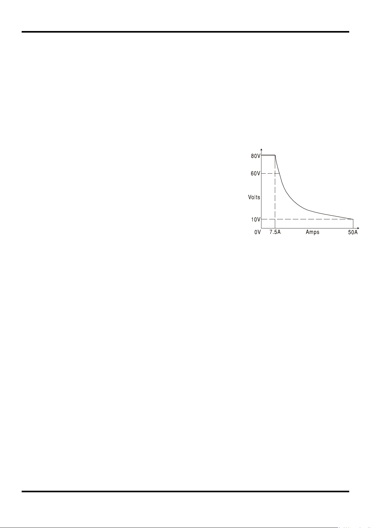
Operating Mode: Constant voltage or constant current
with automatic cross-over provided
that the power demanded stays within
the power envelope, see graph.
Outside of this envelope the output
becomes unregulated. CV, CC or
UNREG mode indication in display.
Output Switch: Independent electronic switching, with ON indication. In addition, BOTH ON
and BOTH OFF keys permit both outputs t o be switched on/off
synchronously (±10µs). Preset voltage and current displayed when off.
Output T erminals: Rear panel safety terminals accepting 6mm wire diameter, 6mm plugs or
8mm spades at 50 Amps max, or 4mm plugs at 30 Amps max.
QPX600D & DP
Power Envelope
(per channel)
Sensing: Switchable between local and remote. Screwless remote sense terminals on
rear panel. Sense miswiring trip and indication.
Ripple & Noise
(20MHz bandwidth):
Load Regulation: Change in output for any load change within PowerFlex envelope, using
Line Regulation: Change in output for a 10% line change:
Transient Response: <2ms to within 100mV of set level for a 5% to 95% load change.
Output Protection: Output will withstand an applied forward voltage of up to 90V.
Over-voltage Protection
(OVP):
Over-current Pr otection
(OCP):
Over-temperature
Protection:
Temperatur e Coefficient: Typically <100ppm/°C
Typically <3mVrms, <20mV pk-pk at maximum load, CV mode
remote sense:
Constant voltage: <0.01% ± 5mV
Constant voltage: <0.01% ± 5mV
Reverse protection by diode clamp for reverse currents up to 3A.
Range 2V to 90V. Resolution 0.1V; accuracy: 0.2% ± 0.2V.
Response time typically 100µs.
Range 2A to 55A. Resolution 0.1A; accuracy: 0.5% ± 0.2A.
Response time typically 100ms.
The output will be tripped off if a fault c auses the internal temperature to rise
excessively.
2

METER SPECIFICATIONS (E ach Output)
Display Ty pe: 5-digit (Volts), 4-digit (Am ps) , black-on-white backlit LCD.
Voltage
(CC Mode and Unreg):
Current
(CV Mode and Unreg):
V x A: Resolution 0·1W
V/A: Meter shows calculated nominal V/A value, together with uncertainty
Resolution 1mV
Accuracy: 0.1% of reading ± 2 dig its
Resolution 10mA
Accuracy: 0.3% of reading ± 2 dig its
Accuracy: 0·5% ± 0·1W
range; 5 digit resolution.
LOGIC CONTROL INPUT and OUTPUT (Each Output)
LOGIC IN is a rear-panel opto-isolated input with an 820Ω resistor in series that is activated at an
input voltage greater than approximately 3.3V. The maximum voltage that can be applied without
damaging the unit is 20V and the input should not be taken negative by more than 3V. User c an
set LOGIC IN (via the keyboard) to enable the output, disable the out put , or be ignored when it is
activated.
LOGIC OUT is an isolated rear-panel open-collector output that will sink up to 2mA when activated
(‘switch closure’); the maximum voltage that can be applied to LOG IC OUT is 30VDC. User can
set LOGIC OUT to be ‘closed’ or ‘open’ for output enabled or disabled, current limit
(CC mode), power limit (UNREG mode), or for any fault trip.
ANALOG REMOTE CONTROL and MONITORING (Each Output)
Quasi-analogue inputs and outputs to set voltage and current limit and t o monitor actual output
voltage and current. The control inputs are read four tim es per second by the
A-D converter and the output is set according t o t he s elect ed input sc aling ; sim ilarly the monit or
outputs are updated four times per s econd with values representing the actual output voltage and
current. These signals each have a range of 0 t o 10V or 0 t o 5V with respect t o the shared COM
return signal; the set range applies to all inputs and outputs.
Analogue Control Voltage Range: Keyboard selectable to be 0 to 10Vdc or 0 to 5Vdc for
range maximum output. Absolute maximum input 20Vdc.
Analogue Control Accuracy: Voltage: 0.3% ± 4mV; Current: 0.5% ± 40m A.
Analogue Control Common Mode Range: ± 2.5Vdc max to negative output.
Analogue Control Input Impedance:
Analogue Monitor Voltage Range: Same as set for Analogue Control Voltage Range.
Analogue Monitor Accuracy: Voltage: 0.3% ± 4mV; Current: 0.5% ± 40m A.
Analogue Monitor Output:
Nominally 40kΩ.
Connect to isolated measuring system with >10kΩ input
impedance. Will withstand a short-circuit.
LINK MODES
In addition to independent output operation, the inst r um ent is capable of operating in a number of
different voltage tracking modes which can be activated f rom the LINK MENU. These modes
include Output 2 voltage (V2) tracking Output 1 voltage (V1) by any ratio in the range 5% to
2000%, V2 and I2 set to track V1 and I 1 (1:1) with total V1 + V2 displayed (useful when Output 1
and Output 2 are series connected), V2 and I 2 set to track V1 and I1 (1:1) with total I1 + I2
displayed (useful when Output 1 and Output 2 are parallel connected).
3

KEYBOARD & ROTARY CONTROL
All functions, including the selection and set-up of the remote control interf ac es, c an be set from
the keyboard. The rotary Jog control can be used to adjust output voltage and current settings in a
quasi-analogue mode. The output to be controlled is first selected with the appropriate Control key.
DISPLAY FEATURES
The displays (one for each output) are graphic LCDs, backlit by white LEDs; contrast is softwarecontrolled and can be adjusted from t he keyboard.
The default status displays show the VOLTS (5 digits) and AMPS (4 digits) in 12mm high
characters, plus output rang e and stat us. At other times, for example during store or recall of
instrument set-ups, the displays show up to 7 lines of information, instructions, or prompts.
INTERFACES (QPX600DP only)
Full digital remote control facilities are available through the RS232, LAN, USB and GPI B
interfaces. Setting and r eadbac k resolutions are the same as for the O ut put and Meter
specifications respectively.
RS232: Standard 9-pin D-connector. Baud rate 9600.
USB: Standard USB 2.0 hardware connection.
LAN: Ethernet 100/10base-T hardware connection..
1.4 LXI Core2011 compliant
GPIB: Conforms with IEEE488.1 and IEEE488.2.
Remote Command
Processing Time:
GENERAL
AC Input: 115V – 240V AC ± 10%, 50/60Hz.
Power Consumption: 1600VA max.
Operating Range: +5ºC to +40ºC, 20% t o 80% RH.
Storage Range:
Environmental: Indoor use at altitudes up to 2000m, Pollution Degree 2.
Store/Recall: Up to 10 set-ups can be saved and recalled via the keyboard or
Safety & EMC: Complies with EN61010-1 & EN61326-1.
Size: 130mm H (3U) x 356mm W x 413mm D
Typically <100ms between receiving the command terminator for a
step voltage change at the instrument and t he out put voltage
beginning to change.
Installation Category II.
−40ºC to + 70ºC.
remote interfaces.
For details, request the EU Declaration of Conformity for this
instrument via http://www.aimtti.com/support
(serial no. needed).
4
Weight: 9.2kg
Options: 19-inch rack kit.
l
Safety
This power supply is a Safety Class I instrument according to IEC classification and has been
designed to meet the requirem ents of EN61010-1 (Safety Requirements for Elect r ical Eq uipm ent
for Measurement, Control and Laborator y Use). It is an Installation Category II instrument intended
for operation from a nor m al sing le phase s upply.
This instrument has been tested in accordanc e with EN61010-1 and has been supplied in a safe
condition. This instruction manual contains some information and warnings which have to be
followed by the user to ensure safe operation and to r etain the inst r um ent in a safe condition.
This instrument has been designed f or indoor use in a Pollution Degree 2 environment in the
temperature range 5°C to 40°C, 20% - 80% RH (non-condensing). It may occasionally be
subjected to temperatures between +5°C and –10°C without degradation of its safety. Do not
operate while condensation is present.
Use of this instrument in a manner not spec ified by these instructions may impair the safety
protection provided. Do not operate the instrum ent outside its rat ed supply voltages or
environmental range.
WARNING! THIS INSTRUMENT MUST BE EARTHED
Any interruption of the mains earth conduct or inside or outside t he inst r um ent will make the
instrument dangerous. Int entional interruption is prohibited. The protective action must not be
negated by the use of an extension cord without a protective conductor.
When the instrument is connected to its supply, t er m inals m ay be live and opening the covers or
removal of parts (except those to which access can be gained by hand) is likely to expose live
parts. The apparatus shall be disconnected from all voltage sources befor e it is opened for any
adjustment, replacement, m aint enance or repair.
Capacitors inside the power supply may still be charged even if the power supply has been
disconnected from all voltage sources but will be safely discharged about 10 m inut es af ter
switching off power.
Any adjustment, maintenance and repair of the opened instrument under voltage shall be avoided
as far as possible and, if inevitable, shall be carried out only by a skilled person who is aware of
the hazard involved.
If the instrument is clearly def ec t ive, has been subject to mechanical damage, excessive moisture
or chemical corrosion the safety protec t ion m ay be impaired and the apparatus should be
withdrawn from use and returned for checking and repair.
Make sure that only fuses with the required rat ed cur r ent and of the specified type are used for
replacement. The use of makeshift fuses and the short-circuiting of fuse holders is prohibited.
Do not wet the instrument when cleaning it.
The following symbols are used on the instrument and in this m anual:-
Earth (ground) terminal.
mains supply OFF.
mains supply ON.
alternating current (ac)
direct current (dc)
Caution – risk of danger. Refer to the documentation (this manual) to find
out the nature of the potential hazard and any act ions which have to be taken.
5

Mains Operating Voltage
This instrument has a universal input range and will operate fr om a nominal 115V or 230V mains
supply without adjustment. Check that the local supply meets the AC Input requirement given in
the Specification.
Mains Lead
Connect the instrument to the AC supply using the mains lead provided. Should a mains plug be
required for a different mains outlet socket, a suitably rated and approved mains lead set should
be used which is fitted with the required wall plug and an IEC60320 C13 connector for the
instrument end. To deter m ine t he m inimum c ur r ent rating of the lead-set f or t he int ended AC
supply, r efer to the power rating information on the equipment or in the Specification.
Any interruption of the mains earth conduct or inside or outside t he inst r um ent will make the
instrument dangerous. Int entional interruption is prohibited.
Mounting
Installation
WARNING! THIS INSTRUMENT MUST BE EARTHED.
This instrument is suitable both for bench us e and r ac k mounting. It is delivered with feet for bench
mounting. The front f eet include a tilt mechanism for optimal panel angle.
A rack kit for mounting in a 19” rack is available from the Manufacturers or their overseas agents.
Ventilation
The power supply is cooled by intelligent multi-speed fans which vent at the rear. Take care not to
restrict the air inlets at the front (top, bottom & side panels) or the exit at the rear. In rack-mounted
situations allow adequate space around the instrument and/or use a fan tray for forced cooling.
6
be taken when using the power supply at voltages above this level.
applied between LOGIC OUT and LOGIC COMmon is 30VDC.
Rear Panel Connections
Output Terminals (each output)
The load should be connected to the positive (red) and negat ive (black ) terminals marked
OUTPUT. The term inals accept 4mm plugs into the end (but note that 4m m plugs will only support
30 Amps), 6mm diameter wire or plugs into t he cr os s -hole or 8mm spade connections (with a
maximum blade width of 16mm). The wiring and connectors must be capable of support ing the
current required; f or 50 Amps, 6mm
Remote sense connections to the load, if r equired, are made from the positive (+) and
negative (−) REMOTE SENSE terminals. Remote sense operation is select ed from the keyboard
or via a remote control interface; R/SNS (Rem ot e Sense) shows in the display beside the output
status ( OFF, CV, CC or UNREG ) when remote sense is selected and goes off when remote
sense is deselected.
2
cable is needed.
Connections
The M4 threaded opening marked
Warning! Voltages above 70Vdc are hazardous live according t o EN 61010-1 and great care must
Always ensure that connections to the terminals are only made in a manner t hat does not
compromise the protection provided by the terminal s t hem sel ves.
Ensure that the contact parts of all connecting wires are fully inserted and inaccessible to the touch.
Always make connections to the instrument w i th the OUTPUT off.
Logic Input (each output)
LOGIC IN is connected to the input of an isolating opto-coupler via an 820Ω resistor in series. The
input is activated by an input voltage greater than approximately 3.3V between LOGIC IN and
LOGIC COMMON; up to 20V may be applied to the input but it should not be taken negative by
more than 3V. The active input current will be between 2mA and 25mA, depending on applied input
voltage. The function of LOGIC IN is set from the keyboard.
Do not apply a voltage to LOGIC IN / LOGIC COMMON exceeding 50V with respect to
Logic Output (each output)
LOGIC OUT is the open-collector output of an opt o-isolated NPN transistor that will sink up to 2mA
when active (‘switch closure’). The function of LOGIC OUT is set f r om the keyboard.
provides a connection point to safety earth gr ound.
.
The maximum voltage that can be
Do not apply external voltages between the terminals exceeding 30VDC.
Analogue Control (each output)
V CONTROL and I CONTROL inputs provide quasi-analogue control of the Output Voltage and
Current Limit respectively. The inputs are read 4 times per second by the A-to-D converter and the
output is set according to the select ed input s caling . The input scaling for both can be set as 0 to
10 Volts or 0 to 5 Volts for range maximum output. The Analogue Control functions and scaling are
both selected from the k eyboard.
The V CONTROL and I CONTROL inputs are differential, with a limited common mode range of
± 2.5Vdc with respect to the negative output. They should be driven from a ‘floating’ source such
as another power supply.
Do not apply external voltages between the terminals exceeding 20Vdc.
7

Pin Name
Description
3
RXD
Received data to instrument
7
DSR
No internal connection
Analogue Monitor (each output)
The output terminal voltage and output curr ent m ay be monitored on V MONITOR and I MONITOR
respectively. The output s caling for both is the same as that set for V CONTROL and I CONTROL,
see previous section.
The Analogue Monitor outputs should be connected to a measuring system with ‘floating’ inputs
such as a DMM.
Do not apply external voltages to these terminals.
RS232 (QPX600DP only)
9−pin female D−connector with pin connections as shown below. Can be connected to a standard
PC port using a fully wired 1:1 male-female cable without any cross-over connect ions.
1 RI
2 TXD Transmitted data from instrument
4 CTS
5 GND Signal ground
6 RTS
Passively asserted (+V through 10kΩ)
Passively asserted (+V through 10kΩ)
8 DTR
9 CD No internal connection
Signal ground is connected to instrument ground.
USB (QPX600DP only)
The USB port is connected to instrument ground. It conforms with USB 2.0 (Full Speed) and
accepts a standard USB cable. The Windows plug-and-play funct ions should aut om at ically
recognise that the instrument has been connected. If the correct driver is not found, follow the
Windows on-screen prompts and install the required files from the CD supplied.
LAN (QPX600DP only)
The LAN interface is designed to meet 1.4 LXI ( Lan eXtensions for Instrumentation) Core 2011.
Remote control using the LAN interf ace is poss ible using a TCP/IP Socket prot ocol. The
instrument also contains a basic Web server which provides information on the unit and allows it to
be configured. Since it is possible to misconfigure the LAN interface, mak i ng it impossible to
communicate with the instrument over LAN, a LAN Configur ation Initialise (LCI) mechanism is
provided via a recessed switch on the rear panel (marked LAN RESET) to reset the unit t o the
factory default.
Further details are given in the Remote Operation chapter. For more information on LXI standards
refer to www.lxistandard.org/home
GPIB (QPX600DP only)
The GPIB signal grounds are connect ed to the instrument ground. The implemented subsets ar e:
The GPIB address is set fr om t he front panel.
8
SH1 AH1 T6 L4 LEO SR1 RL2 PP1 DC1 DT0 C0 E2
This section of the manual is a gener al intr oduction to the controls and operation of the instrument
and is intended to be read before using t he power supply for t he first time. In this manual f r ont
panel keys, connections and indicators are shown in capitals, e.g. ESCAPE, JOG SET, OUTPUT,
ON. Messages shown on the display are printed in a different type-font, e.g.
Limits, CV, Store.
Switching On, Output On/Off
The power switch is located at the bottom left of the front panel.
At power-up the default behaviour is for the instr ument's settings to be restored to those
automatically saved when it was switched off, but with the outputs in independent mode and
always off (
can change this default setting such that the power-down status of the individual outputs and of the
tracking mode are rest or ed at power-up, see the Extra Functions section.
Each DC Output is switched on and off electronically with alternate presses of its key; the ON
lamp illuminates when the Output is on. At the same time the message above the VOLTS and
AMPS display changes from
the present operating mode; should t he load cause t he inst rument to operate outside its
guaranteed power range the display will instead show
BOTH ON or BOTH OFF keys can be used to switch both outputs on or off together; the outputs
switch synchronously within <10µs of each other. Note that, if one output is already on and the
other off, BOTH ON will turn the off output on and BOTH OFF will turn the on output off.
OFF is shown at the top right-hand side of each output ’s display). However, the user
Select Output
The output to be adjusted is selected by pressing CO NTROL 1 or CONTROL 2; the corresponding
LED lamp will light to show which output is currently under the control of the numeric k eypad or
rotary control. Note that the individual
OFF keys, will always operate regardless of which output is currently selected by the CONTROL
keys. Control of Output 1 is t he default setting at power-up.
Keypad
Only the principles of operation are outlined here; the setting of individual parameters is given in
detail in later sections. The paramount consideration in designing the user inter face has been to
make changing setting s as ' s afe' as possible (i.e. with minimal risk of accidentally applying
excessive voltages to a load) whilst achieving ease of use. This has been achieved by requiring
the user to confirm (O K) new numeric set t ings, with the option to ESCAPE at any point or even to
simply pause until the operation times-out and the instrument r et ur ns t o its original settings. In
addition, display messages and LED indicators prompt, g uide or warn the user such that entry or
control errors are minimised. Where some of these features (e.g. beeps) are considered
unnecessary by regular users, the option exists to disable them, see t he Extr a Funct ions s ect ion.
Press CONTROL 1 or 2 to select the output to be adjusted. Under nor m al condit ions t he num eric
keypad is disabled; any numeric key presses will simply be ignored. To set a voltage with the
keypad first press the V NUMERIC SET key; the VOLTS display changes to show the present set
value in a smaller font, with the message Enter V or ESC below it, and the OK lamp starts
flashing. The new value is then entered from the k eyboard; as it is entered it is displayed directly
below the present setting, replacing the pr om pt m es sage. At any time during entry the new setting
can be confirmed with the OK key, e.g. it is sufficient to key in 1, OK to change the s et t ing to
1Volt. When OK is pressed the display reverts to show just the new setting in the f ull-s ize f ont and
the OK lamp stops flashing; if OK is not pressed within 10s of the last numeric key the entry is
cancelled and the display returns to its original setting. If ESCAPE is pressed anytime in the entry
procedure, entry is cancelled and the display returns to its original sett ing. The current limit is set in
exactly the same way after first pressing I NUMERIC SET.
The OK key is used to confirm m ost keypad entries. At all other times it becomes the VIEW V/I
LIMITS key and pressing it will cause the display to show preset output voltage and current limit for
3 seconds; during this period the
Initial Operation
Enter V,
OFF to CV (constant voltage) or CC (constant cur r ent) to indicate
UNREG (unregulated). Alternatively, the
ON keys, as well as the BOTH ON and BOTH
Limits message shows in the display.
9

Pressing SHIFT illuminates the ▲ lamp and gives the numeric keys the functions marked above
them, e.g. STR (Store), RCL (Recall), etc. When a shift function is selected SHIFT is cancelled
(the ▲ lamp is no longer lit). The fur t her key presses required to complete the selected function
are described in detail in the sections that follow; if no key is pressed within 10 seconds to
complete the function, the function will terminate as if ESCAPE has been pressed. SHIFT is a
toggle key; pressing SHIFT again when it has been selected will cancel SHIFT. SHIFT is also
cancelled by ESCAPE, or by pressing SET V or SET I.
Jog Control
The rotary 'jog' control per m its the output voltage or current limit to be incremented or
decremented in steps with a resolution set by the JOG SET keys; the output immediately follows
the setting, i.e. no OK is required.
Press CONTROL 1 or 2 to select the output to be adjusted. At power-up jog is always off. To jog
the voltage or current setting pres s t he V or I JOG SET key; the associated lamp will illuminate and
the appropriate parameter display now changes to two lines. With the output ON the top line
continues to show the actual output, but the additional lower display now shows the present
Limits value; in the lower display, the JO G indicator ( ) is positioned under the digit that was last
jogged. Whilst the V or I JOG SET indicator is lit, each f ur ther press of the V or I key moves the
JOG indicator one digit to the left ; the selection 'wraps-round' such that when the largest value of
jog increment has been reached the next pr ess returns it to the lowest. The default position at
power-up is under the LSD, i.e. the lowest jog increment is selected.
Turning the rotary jog control clockwise/anti-clock wise increments/decr ements the selected digit;
digits to the left of the one being j ogged are automatically incremented/decremented when the
decade overflow/underflow point is reached. Digits to the right of the one being jogged remain
unchanged unless the jog step overf lows/underflows the maximum/minimum settings in which
case they are set to zero. For example, 59·861V goes to 59· 961V goes to 60·000V for a 0.1V jog
increment; 1.60A goes to 0·60A goes to 0·01A for a 1A jog decrement.
The jog steps that can be selected are 1mV, 10mV, 100mV and 10mA, 100mA, 1A.
To disable the jog r otar y contr ol pres s the JOG SET OFF key; reselecting JOG SET V or I will
enable jog on the last used digit position. Jog is not cancelled by using numeric entry or any of the
SHIFT functions but it is disabled whilst that function is enabled. Jog is disabled when control is
switched to the other output using the CONT RO L 1 or 2 keys but is automat ically enabled again
when control is switched back.
Note that the dual display of the parameter being j ogged is primarily of use if the output is O N ; with
the output off both lines of t he display show the
parameter is jogged.
Display
At power-up the display briefly shows the instrument model number and installed firmware revision
in the left-hand display before both displays revert to the standard status display.
The standard status display shows the voltage range and output voltage on the left (above the
front panel VOLTS marking) and the current on the right (above the front panel AMPS marking)
together with the present output stat us, i.e. OFF, CV, CI, or UNREG; if the output is off then
Limits is also shown in the display above the V and I values. The status of the LAN connection
is also shown in the top left corner of the display, as required for LXI compliance. Refer to the
'LAN Status Indication' paragraph in the LAN Interface section for details. Dur ing other operations,
however, the display capabilities are used more extensively to show, for example, prompts during
function settings, e. g. memory store and recall operations or the extra functions accessed via the
shift function; details are given in the relevant sections of this manual.
Limits value and change simultaneously as the
#
10
The display contrast is set at the f act ory but can be adjusted from the keyboard to optimise it for
particular ambient operating conditions. Press SHIFT, # , select Extra Function 90, and follow the
on-screen prompts. Contrast can be adj ust ed independent ly f or the two displays.

Manual Operation – Independent Mode
New users should first read the Initial Operation chapter which describes the operating principles
of the keypad and rotary jog control.
The default mode at power-up is ‘Tracking Off’, i.e. the two outputs are fully independent. The
following sections describe operation of either output in this mode. See the later ‘Manual
Operation – Link Menu’ chapter for details of the various track ing modes that can be set.
Set Voltage Range
There are two voltage ranges for each out put – a low range (0 to 60V) and a high range (0 to 80V).
To select the r ange press SHIFT followed by RANGE. Changing to the higher range is always
possible and the display will show Select 0 to 80V range: 2mV resolution. OK to
confirm, ESC to cancel; pressing OK accepts the change. Because t he r esolut ion of the
80V range is 2mV the set-point will rounded down, if necessary, to the nearest 2mV figure (e.g. if
output is set to 59.997 it will be changed to 59.996).
When changing to the low range the display will show Select 0 to 60V range: 1mV
resolution. OK to confirm, ESC to cancel unless the output is set above 60V in which
case the display will show
to cancel. The output must firs t be set to <60V before the low range can be selected.
Set Voltage
Can’t select 0 to 60V range. Set point too high. Esc
With the output off, the standard status display shows the set voltage; Limits shows as a
reminder beside
(constant voltage) or CC (constant current), depending on the set current limit and load conditions,
and the display shows the actual output voltage (measured at the sense point); note that in CC
mode the actual output voltage will be less than the set voltage. Both the set and actual voltage
are shown to a resolution of 1mV (0-60V range) or 2mV (0-80V range). If t he set voltage and load
conditions cause the instrument to operat e outside its guar ant eed power range the display will
show
The voltage can be set directly from the num er ic keypad: press the NUMERIC SET V key, enter
the new value using the numeric keys and confirm by pressing OK. The broad principles of
keypad entry are explained in the Initial Operation chapter, which should be read by new users.
When SET V is pressed the VOLTS display changes to show the present set value in a smaller
font, with the message Enter V or ESC below it, and the O K lamp star ts flashing. The new
voltage is then entered from the k eyboard, e. g. 12·345V is entered as 1, 2, ·, 3, 4, 5. As it is
entered it is displayed directly below the present setting, replacing the prompt message.
The minimum voltage setting is 0·000V; the maximum setting is 60· 000V (0-60V range) or
80.000V (0-80V range).
Pressing OK at any point will set the voltage entered with any remaining digits set to zero,
e.g. 1, 2, ·, 3, O K will set 12·300V; 1, OK will set 1·000V. When OK is pr ess ed t he s et voltage is
changed and the display reverts to the standard status mode.
Pressing ESCAPE at any time during the sequence, or m aking no further key press within
10 seconds of the previous one will cause the display to return to its original reading before
SET V was pressed.
Entering a voltage outside the range maximum (including tr ying t o ent er 3 digits before the decimal
point) or trying to enter more than 5 digits will cause the buzzer to beep; the last key entry will be
ignored.
The voltage can also be set using the Jog control. Pr ess ing J O G SET V will illuminate the V JOG
SET lamp and the VOLTS display will again change to two lines. With the output O N t he t op line
continues to show the actual output, but the additional lower display now shows the present
UNREG (unregulated) and the actual output voltage will again be less than the set voltage.
OFF in the top line of the display. With the output ON the mode changes to CV
Limits value; in the lower display, the JO G indicator ( ) is positioned under the digit that was last
jogged. Whilst the V SET lamp is lit, each further press will move the
the left; the selection 'wraps round' such that when the larg es t value of jog increment has been
reached the next press returns it to t he lowest.
JOG indicator one digit to
11
 Loading...