

Page 1

QL Series II
Precision Power Supplies
INSTRUCTION MANUAL
Page 2

Table of Contents
Introduction 2
Specification 4
Safety 7
Installation 8
Connections 9
Front Panel Connections 9
Rear Panel Connections 9
Initial Operation 11
Manual Operation 14
Main Outputs 14
Main Outputs – Link Mode (T models only) 21
Main Outputs – Copy Function (T models only) 23
Auxiliary Output (T models only) 23
Remote Operation (P models only) 24
Interface Locking 24
Address & Baud Rate Selection and Interface Status View 24
Remote/Local Operation 25
RS232 Interface 25
USB Interface 26
LAN Interface 26
Status Reporting 30
Remote Commands 34
RS232/USB Remote Command Format 34
GPIB Remote Command Formats 34
Command List 35
Maintenance 40
Note: The latest revisions of this manual, device drivers and software tools can be
downloaded from: http://www.aimtti.com/support.
This manual is 48511-1560 Issue 8
1
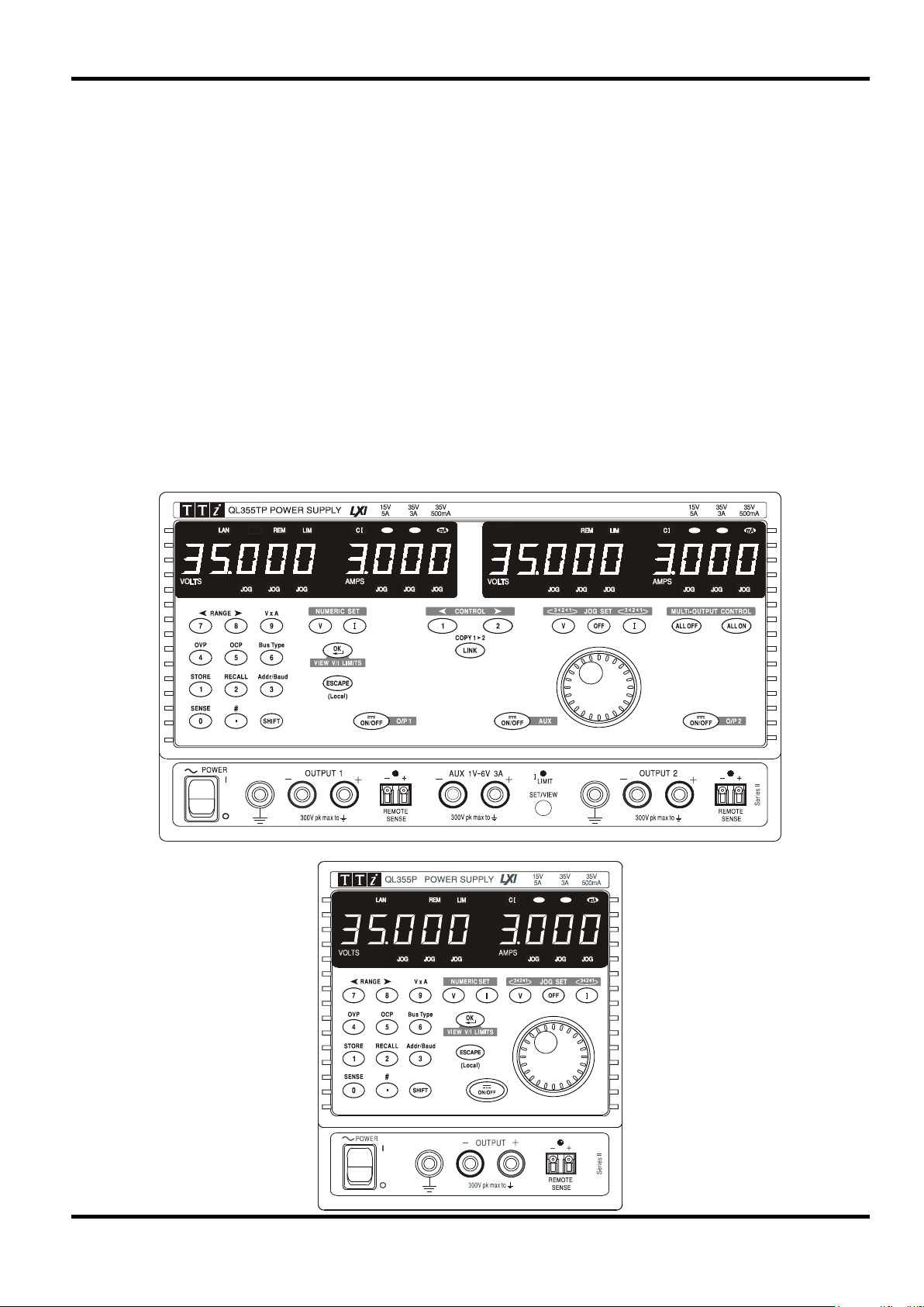
Page 3

Unmatched Precision, Unrivalled Performance
The QL series II provides the highest perform ance levels available in a laboratory power supply.
Voltage and current are controlled using 16 bit DACs enabling voltages t o be set to 1mV resolution
even at full output. Indeed, the accurac y is suff icient for the PSU to be used as a calibration
source for some hand-held DMMs.
The QL series II uses pure linear technology and offers unrivalled perfor m anc e in terms of
regulation, output noise and dynamics. Line and load regulation are c lose t o t he limit of
measurement. Output noise is less t han 350µV r m s in CV mode and down to 20µA rms in CI
mode. Recovery time from transient cur rent pulses is better than 50µs.
It provides full remote sense capability via dedicated sense terminals. Remote sense is ess ent ial
to maintain precise regulation at the load. When remote sense is not req uired, internal local
sensing can be selected at the touch of a but ton.
Multiple Ranges for Greater Flexibility
The QL series II provides multiple ranges for increased cur r ent capability at lower voltages. The
main range offers 0 to 35 Volts at up to 3 Amps (QL355) or 0 to 56 Volts at up to 2 Amps (QL564).
The higher current rang e pr ovides up to 5 Amps for voltages up to 15V (QL355) or 4 Amps for
voltages up to 25V (QL564). A further low current range provides enhanced current set ting and
measurement resolution of 0·1m A.
The product of voltage and current c an be displayed at any time by pressing the VxA button. The
power is displayed to a resolution of 0·01 Watts.
Introduction
Fast, Simple and Safe to use
The user interface of the QL series II has been carefully designed to provide rapid control whilst
guarding against any possibility of error.
Voltage and current setting can be per formed either by direct numeric entry or, for applications
where the voltage or current must be gradually changed, by using t he quasi-analogue Jog control.
To enable the current limit t o be s et before connecting the load, the limit sett ing is displayed when
the output is off. Pressing t he View Limits key at any time provides a temporary display of the limit
values allowing precise adjustment to also be made with the output on.
Setting Memories for Added Convenience
The QL series II provides storage of up to 50 power supply sets-ups in non-volatile memory for
each main output, plus (T models only) a further 50 set-ups for linked mode operation, plus 10 setups for the auxiliary output. Upon mains switch-off, the set -up of the PSU is saved and is
automatically restored at switch-on.
OVP and OCP Trips with 'Alarm' Output
The QL series II provides fully adjustable over-voltage and over-current trips which can be used
both as a fail-safe against acc idental mis-s et t ing and as a protection against inappropriate load
conditions. In addition to turning the out put off, a trip condition switches the rear panel alarm
signal enabling other equipment to be cont r olled.
For complete protection of t he power supply, the trip will also be operated by over-temperature or
excess voltage on the sense terminals.
Auxiliary Output with Fully Variable Vol tage (T models)
The QL series II triple output power supplies incorporate an auxiliary output which is fully variable
between 1 volt and 6 volts to a resolution of 0.01V, and has a current capability of 3 amps.
A front panel button enables to voltage and current for the auxiliary output to be viewed on the
Output 1 display whenever required.
2
Page 4
Fully Programmable via GPIB, RS232, USB or L AN
The programmable ‘P’ models incorporate a full bus interface permitting remote control and
readback via either GPIB (IEEE-488), RS232, USB or LAN.
The GPIB interface conforms fully with IEEE-488.2 and IEEE-488.1.
The RS232 interface uses a standard 9-pin D-connect or and has a Baud r at e variable from 600
to 19200.
The USB interface is compatible with USB 2.0 and USB 1.x.
The LAN interface is 1.4 LXI Cor e 2011 compliant.
The QL series II uses simple and consistent command struc t ur es which make programming
particularly easy regardless of which interface is used.
An IVI driver for Windows is included. This provides support for common high-level applications
such as LabView*, LabWindows*, and HP/Agilent VEE*.
All power supply settings can be controlled via the bus. Voltage and current can be set to a
resolution of 1mV or 0·1mA (main outputs). Actual voltage and current can be read back
together with the power supply status.
* LabView LabWindows is a trademark of National Instrument s Corp. Agilent VEE is a trademark of Agilent Technologies i nc.
3
Page 5

Voltage/Current Ranges:
QL355
QL564
0V to 15V/0·001A to 5A
0V to 25V/0·001A to 4A
Accuracy ± (0·03% + 5mV)
Accuracy ± (0·2% + 5mA); ± (0· 2% + 0· 5m A) on 500m A range.
CI indicator lit in constant current mode.
Preset voltage and current limit displayed when Output off.
Duplicate rear panel Output and Sense screw terminals on P models.
load to half load or vice versa.
Speed:
excursion (for resistive load). Excludes command processing t im e.
QL355
QL564
Load
Load
Up
35V 500mA
200ms
40ms
56V/500mA
300ms
60ms
Down
35V 500mA
120ms
600ms
56V/500mA
200ms
800ms
(20MHz bandwidth):
Normal mode current: <0·2mAr m s; <20µArms on 500mA range.
Specification applies for sense lead resistance <0·5Ω.
Current <0·01% + 250µA; <0.01%+ 50µ A on 500mA range.
typically<(100ppm + 0·1mA)/°C on 500mA range.
General specifications apply for the tem per ature range 5°C to 40°C. Accuracy specifications
apply for the temperature range 18°C to 28°C after 1 hour warm-up with no load and calibration
at 23°C. Typical specifications are determined by design and are not guaranteed.
MAIN OUTPUTS
Specification
0V to 35V/0·001A to 3A
0V to 35V/0·1mA to 500mA
Voltage Setting: Resolution 1mV
Current Setting: Resolution 1mA; 0·1mA on 500mA range
Output Mode: Constant voltage or constant current with automatic cross-over.
Output Switch: Electronic, non isolating. Switch illuminated when Output on.
Output T erminals: Universal 4mm safety binding posts on 19mm (0·75”) pit c h for Output;
screwless terminals for Sense.
Transient Response:
Voltage Programming
<50µs to within 15mV of set level for a change in load current from full
Maximum time required for output t o set tle within 1% of its total
Full Load
No
0V to 56V/0·001A to 2A
0V to 56V/0·1mA to 500mA
Full Load No
Up
Up
Down
Down
Ripple and Noise
Load Regulation: For any load change, measured at the output t er m inals, using
Line Regulation: Voltage <0·01% + 2mV for 10% line change.
Temperatur e Coefficient: Voltage: typically <(50ppm + 0·5mV)/° C
15V 5A
35V 3A
15V 5A
35V 3A
Normal mode voltage: <0·35mVrms and 2mVp-p
remote sense.
Voltage <0·01% + 2mV.
Current <0·01% + 250µA; <0.01% + 50µ A on 500mA range.
Add typically 2·5mV for a 0·5V drop in the positive output lead.
Current: typically <(100ppm + 1mA)/°C;
6ms
20ms
6ms
25ms
6ms
7ms
250ms
600ms
25V/4A
56V/2A
25V/4A
56V/2A
10ms
40ms
10ms
50ms
6ms
15ms
400ms
800ms
4
Page 6

Response time typically 100µs
Response time typically 35ms
Protection Functions:
Output trips off for OVP, OCP, over-temperature and Sense miswiring
Display Ty pe:
5-digit (Volts), 4-digit (Amps), 14mm (0·56") LED.
Accuracy ± (0·1% of reading + 10mV)
Accuracy ± (0·2% + 0·005A); ± (0· 2% + 0· 5mA) on 500mA range
Accuracy ± (0·3% + 0·05W); ± (0·3% + 0·005W) on 500mA range
Voltage Range:
1V to 6V
Accuracy: ± 0.5% ±10mV
Current Limit:
3A minimum
Output Switch:
Electronic, non isolating. Switch illuminated when Output on.
screwless terminals on rear panel.
protection for currents up t o 1A. Over-current tr ip.
(20MHz bandwidth)
Load & Line Regulation:
<1·0% for a 90% load change; 0· 1% for a 10% line change.
(use SET/VIEW button)
Current Meter: Resolution 10mA, accuracy ± 0.5% ±10m A
Speed:
excursion (for resistive load). Excludes command processing time.
1V to 6V: 10ms, no load and full load
6V to 1V: 10ms, no load and full load
Output Protection: Output will withstand forward voltages of up to 20V above rated output
voltage. Reverse protection by diode clamp for currents up t o 3A.
Over-voltage Protection:
(OVP)
Over-current Pr otection:
(OCP)
Range 1V to 40V (QL355), 1V to 60V (QL564)
Resolution 0·1V; accuracy ± (2% + 0·5V)
Range 0·01A to 5·5A (Q L355), 0·01A to 4·4A (QL564)
Resolution 0·01A; accuracy ± (0·2% + 0·01A)
METER SPECIFICATIONS (Main Outputs)
Voltage (CI mode) : Resolution 10mV
Current (CV mode): Resolution 0·001A; 0·1mA on 500mA range
V x A: Resolution 0·01W; 0·001W on 500mA range
AUXILIARY OUTPUT (T models only)
Voltage Setting: Resolution: 10mV
Output T erminals: Universal 4mm safety binding posts on 19mm (0·75”) pit c h. Duplicate
Output Protection: Output will withstand up to 16V forward voltage. Diode clamp reverse
Ripple & Noise:
Status Indication: Current limit lamp. Current overload trip indication.
Meter Specifications:
Voltage Programming
<2mV rms, 10mVp-p
Voltage Meter: Resolution 10mV, accuracy ± 0.5% ±10mV
Maximum time required for output to settle within 1% of its total
KEYBOARD & ROTARY CONTROL
All functions, including the selection and set-up of the remote control interf ac es, c an be set from
the keyboard. The rotary jog control can be used to adj ust output voltage and current settings in
a quasi-analogue mode.
5
Page 7

General
RS232:
Standard 9-pin D-connector. Variable Baud rat e ( 600 to 19200).
GPIB:
Conforming with IEEE488.1 and IEEE488.2
USB:
Standard USB 2.0 hardware connection. Operates as a virtual COM port.
LAN:
Ethernet 100/10base-T hardware connection. 1.4 LXI Core 2011.
change.
Status Indication:
Remote mode and LAN status indicators
Main Outputs
Voltage Setting:
16-bit; Resolution 1mV, accuracy ± (0·03% +5mV)
Resolution 0.01mA, Accuracy ± (0·2% + 0·5mA) on 500mA range.
Readback V & I
See meter specifications.
Auxiliary Output (T models only)
Voltage Setting:
Resolution 10mV, acc ur acy ± 0. 5% ±10mV
Current Setting:
Resolution 10mA, accuracy ± 0.5% ±10mA
Readback V & I
See meter specifications
Installation Category II
Power Consumption:
Single output: 250VA max; Triple output: 500VA max.
Operating Range:
+5ºC to +40ºC, 20% to 80% RH
Storage Range:
−40ºC to + 70ºC
Environmental:
Indoor use at altitudes up to 2000m, Pollution Degree 2.
output if internal temperat ur es exceed predet er m ined t hr es holds.
interfaces.
instrument via http://www.aimtti.com/support (serial no. needed).
Triple output: 280 x 160 x 290mm (WxHxD), excl. feet & t er m inals
ALARM OUTPUT
Isolated rear-panel open-collector output signal. User can s elect out put to be activated for either
OVP, OCP, Overtemperat ure or Sense miswiring, or for any of those four faults.
DIGITAL INTERFACES (P models only)
Full digital remote control facilities are available through the RS232, USB, LAN and G PI B inter faces.
Remote Command
Processing Time:
Current Setting: 16-bit; Resolution 0.1mA, accuracy ± (0·2% + 5m A)
GENERAL
AC Input: 230V AC or 115V AC ± 10%, 50/60Hz
Typically <25ms between receiving the command terminator for a step
voltage change at the instrument and the out put voltage beg inning to
Cooling: Intelligent variable-speed fan. Over-t em per ature trip shuts down
Store/Recall: Up to 50 set-ups each main output, 50 linked set-ups, and 10 auxiliary
output settings can be saved and recalled via the keyboard or remote
Safety: Complies with EN61010-1 & EN61326-1.
For details, request the EU Declaration of Conformity for this
Size: Single output: 140 x 160 x 290mm (WxHxD), excl. feet & terminals.
Weight: Single: 5.5kg; Triple: 10·5kg
6
Page 8

l
Safety
This power supply is a Safety Class I instrument according to IEC classification and has been
designed to meet the requirem ents of EN61010-1 (Safety Requirements for Elect r ical Eq uipm ent
for Measurement, Control and Laborator y Use). It is an Installation Category II instrument
intended for operation from a normal single phase supply.
This instrument has been tested in accordanc e with EN61010-1 and has been supplied in a safe
condition. This instruction manual contains some information and warnings which have to be
followed by the user to ensure safe operation and to r etain the inst r um ent in a safe condition.
This instrument has been designed f or indoor use in a Pollution Degree 2 environment in the
temperature range 5°C to 40°C, 20% - 80% RH (non-condensing). It may occasionally be
subjected to temperatures between +5°C and –10°C without degradation of its safety. Do not
operate while condensation is present.
Use of this instrument in a manner not spec ified by these instructions may impair the safety
protection provided. Do not operate the instrum ent outside its rat ed supply voltages or
environmental range.
WARNING! THIS INSTRUMENT MUST BE EARTHED
Any interruption of the mains earth conduct or inside or outside t he inst r um ent will make the
instrument dangerous. Int entional interruption is prohibited. The protective action must not be
negated by the use of an extension cord without a protective conductor.
When the instrument is connected to its supply, terminals may be live and opening the covers or
removal of parts (except those to which access can be gained by hand) is likely to expose live
parts. The apparatus shall be disconnected from all voltage sources before it is opened for any
adjustment, replacement, m aint enance or repair.
Capacitors inside the power supply may still be charged even if the power supply has been
disconnected from all voltage sources but will be safely discharged about 10 m inut es af ter
switching off power.
Any adjustment, maintenance and repair of the opened instrument under voltage shall be
avoided as far as possible and, if inevitable, shall be carried out only by a skilled person who is
aware of the hazard involved.
If the instrument is clearly def ec t ive, has been subject to mechanical damage, excessive
moisture or chemical corrosion the safety protection may be impaired and the apparatus should
be withdrawn from use and returned for checking and repair.
Make sure that only fuses with the required rated current and of the specified type are used f or
replacement. The use of makeshift fuses and the short-circuiting of fuse holders is prohibited.
Do not wet the instrument when cleaning it.
The following symbols are used on the instrument and in this manual:-
Earth (ground) terminal.
mains supply OFF.
mains supply ON.
alternating current (ac)
direct current (dc)
7
Page 9
BROWN BLUE BROWN BLUEBROWN
115V230V
for 230V operation:
1.6A (T) 250V HBC
for 115V operation:
3.15A (T) 250V HBC
for 230V operation:
4A (T) 250V HBC
for 115V operation:
8A (T) 250V HBC
for 230V operation:
1.6A (T) 250V HBC
for 115V operation:
3.15A (T) 250V HBC
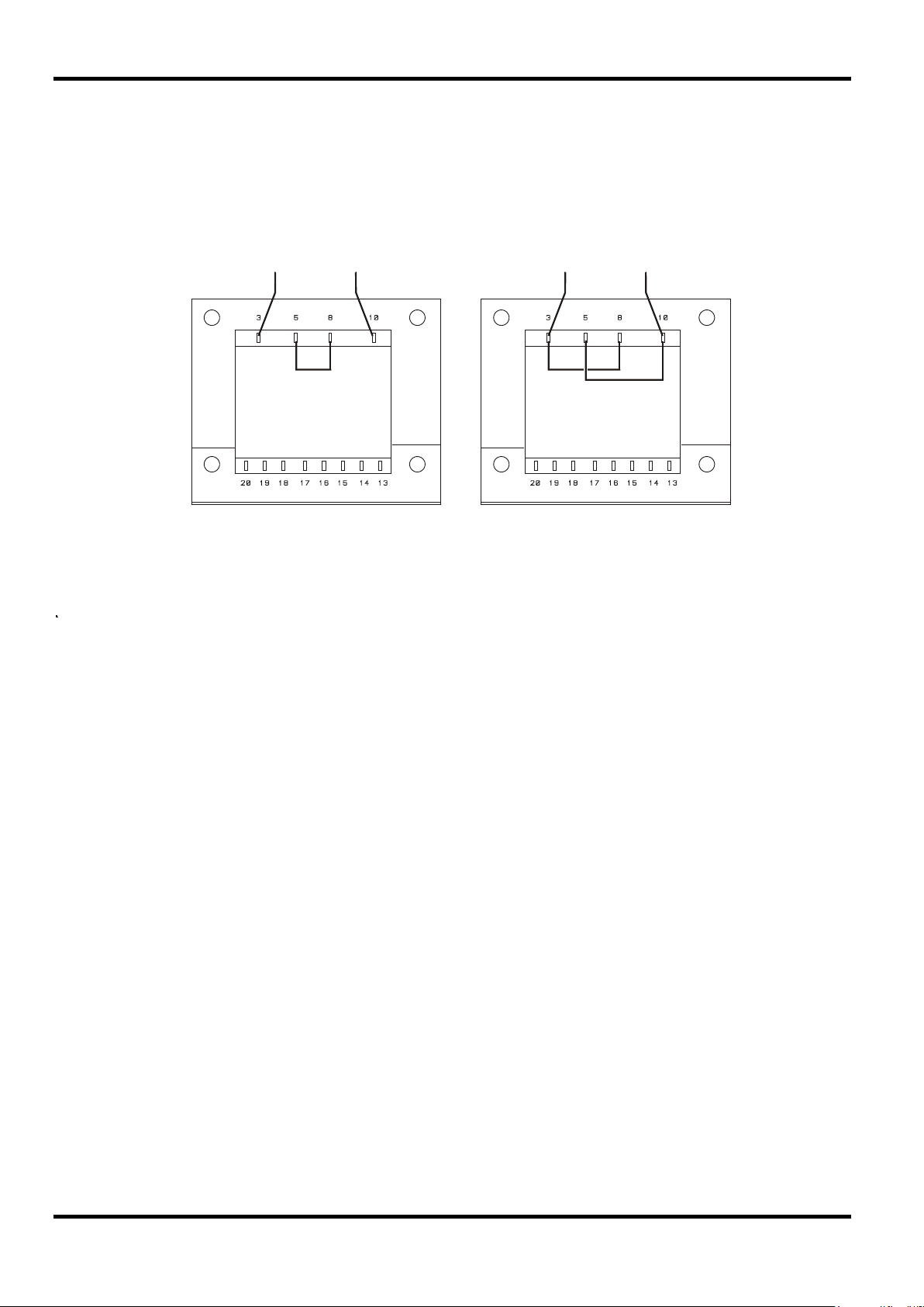
Installation
Check that the instrument oper ating voltage marked on the rear panel is suitable for the local
supply. Should it be necessary to change the operating voltage, proceed as follows:
1) Disconnect the inst r um ent from all voltage sources.
2) Remove the screws which retain the top cover and lift off t he c over.
3) Change the connec t ions on bot h transformers following the appr opriate diagram below:
4) Refit the cover and the secure with the same screws.
5) To comply with safety standard requirements the operating voltage mar ked on the rear panel
must be changed to clearly show the new voltage setting.
6) Change all three fuses to ones of the correct r at ing, see below.
Fuse
The AC inlet fuse is located in the fuse drawer in the lower part of the IEC inlet connector. To
change the fuse remove the line cord and open the fuse drawer with a suitable tool.
QL355, QL355P, QL564 & QL564P
The correct mains fuse t ype is 20 x 5mm 250V HBC time-lag with the following rating:
QL355T, QL355TP, QL564T & QL564TP
The correct mains fuse t ype is 20 x 5mm 250V HBC time-lag with the following rating:
In addition, the two transformer s ar e individually fused inside the power supply. To access these
fuses remove the cover as described above; both f uses are clipped to the small PCB which is
fitted directly onto the pins of t he IEC inlet connector itself.
The correct fuse type is 20 x 5mm 250V HBC time-lag with the following rating:
Make sure that only fuses with the required current r ating and of the specified type are used for
replacement. The use of makeshift fuses and the short-circuiting of fuseholders are prohibited.
8
Page 10

Mains Lead
Connect the instrument to the AC supply using the mains lead provided. Should a mains plug be
required for a different mains outlet socket, a suitably rated and appr oved mains lead set should be
used which is fitted with the required wall plug and an IEC60320 C13 connector for the instrument
end. To determine the minimum current rating of the lead-set for the intended AC supply, refer to the
power rating information on the equipment or in the Specification.
Any interruption of the mains earth conductor inside or outside the inst rument will make the
instrument dangerous. Intentional interruption is prohibited.
Mounting
This instrument is suitable both for bench use and rack mounting. It is delivered with feet for
bench mounting. The front f eet include a tilt mechanism for optimal panel angle.
A rack kit for mounting QL Series power supplies is available from the Manufacturers or their
overseas agents. The rack will accommodate 1, 2 or 3 single units or a tr iple and single unit; a
blanking piece is also available for unused positions in the rack .
Ventilation
The power supply is cooled by an intelligent multi-speed fan which vents at the rear. Take care
not to restrict the air inlets at the side panels or the exit at the rear. In rack-mounted situations
allow adequate space around the instrument and/or use a fan tray for forced cooling.
WARNING! THIS INSTRUMENT MUST BE EARTHED.
Front Panel Connec tions
The loads should be connected to the positive (red) and negat ive (black ) terminals marked
OUTPUT 1, OUTPUT 2, o r AUX.
Remote sense connections to the loads on Outputs 1 or 2, if required, are made from t he
corresponding positive (+) and negative (−) REMOTE SENSE term inals. Rem ot e s ense
operation is selected from the keyboard or via a remote control interface (P models only); the
REMOTE SENSE lamp is lit when remote sense is selected. Switching off remote sense ret ur ns
the instrument to local sensing at the output terminals.
The terminal marked
is connected to the chassis and safety earth ground.
Rear Panel Connections
Main Output Terminals (P models only)
The output and sense terminals are duplicated on the rear panel screw-terminal block marked
Output +, Output −, Sense + and Sense − ; these connections are paralleled with their front panel
equivalents.
Connections
Remote sense operation is selected from the keyboard or via a remote control interface. When
the rear panel terminals are used, remote sense should always be selected to ensure t hat output
regulation is maintained within specification.
Auxiliary Output Terminals (T models only)
The front panel AUX OUTPUT terminals are duplicated on the rear panel with screwless
terminals marked AUXILIARY OUTPUT.
9
Page 11

5
GND
Signal ground
9
CD
No internal connection
Alarm Outputs
Associated with each main output are recessed 2-pin connectors marked Alarm. These provide
access to an opto-isolated NPN swit ching transistor, the function of which can be set from the
keyboard, see the Alarm Output section of this manual.
The maximum operating voltage that can be applied across t he t er minals is 20VDC and the
maximum sink current for t he s witch 'closur e' is 1m A.
Do not apply external voltages between the terminals exceeding 30VDC.
RS232 (P models only)
9−pin female D−connector with pin connections as shown below. Can be connected to a
standard PC port using a fully wired 1:1 male-female cable without any cross-over connections.
Pin Name Description
1 RI
2 TXD Transmitted data from instrument
3 RXD Received data to instrument
4 CTS
Passively asserted (+V through 10kΩ)
Signal ground is connected to instrument ground.
USB (P models only)
The USB port is connected to instrument ground. It conforms with USB 2.0 (Full Speed) and
accepts a standard USB cable. The Windows plug-and-play funct ions should aut om at ically
recognise that the instrument has been c onnected. If the correct driver is not found, follow the
Windows on-screen prompts and install the required files from the CD supplied.
LAN (P models only)
The LAN interface is designed to meet 1.4 LXI ( Lan eXtensions for Instrumentation) Core 2011.
. Remote control using the LAN interface is possible using a TCP/IP Socket protocol. The
instrument also contains a basic Web server which provides information on the unit and allows it
to be configured. Since it is possible to misconfigure the LAN interface, making it impossible to
communicate with the instrument over LAN, a LAN Configur ation Initialise (LCI) mechanism is
provided via a recessed switch on the rear panel (marked LAN RESET) to reset the unit t o the
factory default.
Further details are given in the Remote Operation chapter. For more information on LXI
standards refer to www.lxistandard.org/home
6 RTS
Passively asserted (+V through 10kΩ)
7 DSR No internal connection
8 DTR
GPIB (P models only)
The GPIB signal grounds are connect ed to the instrument ground. The implemented subsets are:
The GPIB address is set fr om t he front panel.
10
SH1 AH1 T6 TE0 L4 LE0 SR1 RL2 PP1 DC1 DT0 C0 E2
Page 12

This section of the manual is a gener al intr oduction to the controls and operation of the
instrument and is intended to be read befor e us ing the power supply for the first time.
In this manual front panel keys, connections and display indicators are s hown in capitals,
e.g. STORE, ESCAPE, OUTPUT, JOG. Messages shown on the 7-segm ent display are printed
in a different type-font, e.g.
characters as they are shown on the 7-segment display.
StorE, GPIb, triP in upper or lower case to represent the
Switching On, Output On/Off
The power switch is located at the bottom left of the front panel.
At power-up the default behaviour is for the instr ument's settings to be restor ed t o those
automatically saved when it was switched off, but with all outputs always off. However, the us er
can change the default setting such that selected outputs are restored at power-up t o their status
at power-down, see the Extra Functions section.
The DC outputs are switched electronically with their respective ON/OFF keys; the k ey
illuminates when the output is on. In addition, all outputs can be switched on and off toget her
using the ALL ON and ALL OFF keys.
Synchronous Output On/Off Switching (T models only)
Pressing ALL OFF at any time will synchronously turn off any outputs that are on; under the same
load conditions outputs will typically turn off within 1ms of each other. With all outputs off the ALL
OFF key is illuminated green. Pressing the ALL ON key when all the outputs are off will turn all
the outputs on synchronously; outputs with identical settings and load conditions will typically turn
on within 1ms of each other. However, if one output is already on, pressing ALL ON will turn the
remaining outputs on but the turn-on delay between the outputs will be up to 80ms, even with the
same output setting and load conditions.
Initial Operation
Keypad
Only the principles of operation are outlined here; the set ting of individual parameters is given in
detail in later sections.
The paramount consideration in designing the user int er face has been to make changing settings
as 'safe' as possible (i.e. with minimal risk of accidentally applying excessive voltages to a target
system) whilst achieving ease of use. This has been achieved by requiring the user to confirm
(OK) new numeric settings, with the option to ESCAPE at any point or even to simply pause until
the operation times-out and the instr um ent r eturns to its original settings.
In addition a buzzer, illuminated keys, LED indicators and display messages prompt, guide or
warn the user such that entry or control error s ar e m inimised. Where some of t hese features
(e.g. beeps or flashing indicator s) ar e c onsider ed unneces sar y by regular user s , the option exists
to disable them, see the Extra Functions section.
On triple output (T) models t he ability to change settings from the k eypad or by using the Jog
controls is assigned to Output 1, Output 2 or both by using the 1, 2 or LINK CONTROL keys
respectively. The key (1 or 2) as soc iated with the selected output illuminates to show which
output is under control. In LINK mode (bot h keys lit) both outputs are controlled at the same
time, including some of the shifted operations (RANGE, STORE, RECALL and V x A). The
further descriptions that follow apply to either or both main outputs as appropriate to the setting
indicated by the illumination of the CONTROL keys.
Under normal conditions the numeric keypad is disabled; pressing any key will cause the buzzer
to make a double beep, indicating an illegal operation. To set a voltage or current with the
keypad press the V or I NUMERIC SET key; the appropriate display shows 0·000V or 0·000A
with the digit to the left of the decim al point flashing. Digits are entered in response to t he
flashing prompt, together with the decimal point at the appropriate time, and t he ent r y is
confirmed with the OK key. If OK is not pressed within 10 seconds of the last numeric key the
entry is cancelled and the display returns to its original setting. I f ESCAPE is pressed anywhere
in the entry procedure, entry is cancelled and the display returns to its orig inal setting.
11
Page 13

The OK key is used to confirm m ost keypad entries. At all other times it becomes the VIEW V/I
LIMITS key and pressing it will cause the display to show preset output voltage and current limit
for 3 seconds; during this per iod t he LI M indicator in the display flashes.
Pressing SHIFT illuminates the key and gives the numeric keys the functions marked above them
(e.g. STORE, RECALL, etc.). When a function is selected by pressing one of these keys SHIFT
is cancelled (the SHIFT key is no longer lit). The further key presses required to complete the
selected function are described in detail in the sections that follow; if no key is pressed within 10
seconds to complete the function, t he function will terminate as if ESCAPE has been pressed.
SHIFT is a toggle key; pressing SHIFT again when it has been selected will cancel SHIFT.
SHIFT is also cancelled by ESCAPE, or by pressing SET V or SET I. Note that in LINK mode
settings accessed by STORE and RECALL are specific to the LINK mode and are in addition to
settings accessible when STORE and RECALL are used on individually selected outputs.
Jog Control
The rotary 'jog' contr ol per m its the output voltage or current limit to be incremented or
decremented in steps with a resolution set by the JOG SET keys; the output im m ediat ely f ollows
the setting, i.e. no OK is required.
At power-up jog is always off. To jog the voltage or current setting press the V or I JO G SET key;
the key will illuminate and the JOG indicator under the digit that was last j ogged will flash. Whilst
the V or I JOG SET key is lit, each furt her pr es s of the V or I key moves the JOG indicator one
digit to the left; the selection ' wraps-round' suc h t hat when the largest value of jog increment has
been reached the next press returns it to t he lowest. The def ault posit ion at power-up is under
the LSD, i.e. the lowest jog increment is select ed.
Turning the rotary jog control clockwise/anti-clockwise increments/decrements the selected digit;
digits to the left of the one being jogged are automatically incremented/decrem ent ed when the
decade overflow/underflow point is reached. Digits to the right of the one being jogged r em ain
unchanged unless the jog step overf lows/underflows the range maximum/minimum in which case
they are set to zero. On the QL355, for example, 33·65V goes to 34·65V goes to 35·00V for the
35V range and a 1V jog increment; 0· 160A goes to 0·060A goes to 0·001A for a 0·1A jog
decrement.
The jog steps that can be selected for the main range are 1mV, 10mV, 100mV and 1mA, 10mA,
100mA; if the 500mA range has been selected the current increment st eps are 0· 1m A, 1m A,
10mA.
To disable the jog r otar y contr ol pr ess the JOG SET OFF key; reselecting JOG SET V or I will
enable jog on the last used digit position. Jog is not cancelled by using numeric entry or any of
the SHIFT functions but it is disabled whilst that function is enabled.
When in constant voltage mode, with the output on, the right-hand display will show actual
current rather than curr ent limit . If JOG SET I is selected the JOG indicator under the selected
digit will flash at h a lf-speed ('lazy' flash). To obser ve the effect of jogging the current limit it will
be necessary to either turn the output off (so that the display permanently shows the current limit)
or to press VIEW V/I LIMITS which causes the current limit to be displayed until 3 seconds after
movement of the jog cont r ol ceases . The 'lazy' flash is also used when JOG SET V has been
selected and actual voltage is being shown because the supply has gone into current limit.
The factory default is t o flash the JOG indicator under the selected digit for the whole time that
jog is selected so that the user is cons tantly reminded which parameter can be incr em ent ed/
decremented. Where this degree of reminding is consider ed inadeq uate the user can select,
using the Extra Functions capability, to flash the digit itself; conversely, where the flashing is
considered intrusive the user can select to not f lash t he JOG indicator (except when the 'lazy'
flash is shown).
12
Page 14

Display
The displays shows the voltage on the left (5 digits) and the current on the r ight (4 digits) for both
the main outputs. These 7-segment displays are also used to show prompts during some of the
function settings (e. g. memory store/recall or remote cont rol address setting) using the limited
'character set' that c an be achieved with a 7-segm ent display; thes e ar e neces sar ily a mixture of
upper and lower case letters.
Above and below the 7-segment display are several secret-until-lit annunciators.
To the rig ht , above the current display, ar e the indicators which show the selected operating
range: 35V/3A, 15V/5A or 35V/500mA (QL355T & TP) or 56V/2A, 25V/5A or 56V/500mA
(QL564T & TP); the indicators light beneath the range printed immediately above them and, in
the case of the 500mA range, the indicator is marked mA to emphasise that the current display is
now showing mA.
The other annunciators above the displays are:
CI, indicating that the instrum ent is in constant cur r ent mode;
LIM, which flashes when the VIEW V/I LI MITS key is pressed to show the set voltage/set current
limit in the display;
REM, which lights when the instrument is under control from a remote interface (P models only)
and LAN, which indicates the status of the LAN interface connection (P models only).
Below the three least significant digits of bot h the voltage and current displays are the JOG
indicators; the appropriate indicator flashes when the jog function is being used, see the Jog
Control section above.
The display of Output 1 can alternatively be used to show the voltage and current of the AUX
output (T models only). Full details are given in the Auxiliary Output section.
13
Page 15

Main Outputs
New users should first read the Initial Operation chapter which describes the operating principles
of the keypad and rotary jog control. The following paragraphs des cr ibe t he independent
operation of either Main Output. To select which output is to be controlled by the keypad/Jog
controls it is first necessary to select t hat output by pressing the appropriate CONTROL key
(1 or 2); the key lights to show that it is the select ed output.
The additional features available on the triple output (T) models in LINK mode (both Main
Outputs selected) are described in the Main Outputs – Link Mode section later in this m anual.
Set Voltage
The left-hand display shows the set voltage to a resolution of 1mV, except when the instrument is
in constant current (CI) mode. I n CI mode the actual output voltage (which will be less than the
set voltage) is shown and the display resolution is 10mV; the least significant digit (1mV
resolution) is always displayed as a zero.
The voltage can be set directly from the numer ic keypad: press the NUMERIC SET V key, enter
the new value using the numeric keys and confirm by pressing OK. The broad principles of
keypad entry are explained in the Initial Operation chapter, which should be read by new users.
Manual Operation
When SET V is pressed the display shows 0·000; a new voltage is then entered (e.g. 12·345V is
entered as 1, 2, ·, 3, 4, 5) and c onfirmed by OK. The position of the decimal point in the display
is fixed to reduce the risk of ent er ing a wrong value. As a consequence, and to avoid the need to
enter leading zeroes (e.g. 2·345V is enter ed as 2, ·, 3, 4, 5, OK), numbers to t he lef t of the
decimal point are shown slightly differently to the numbers to the right of the decimal point during
number entry; this is self-evident during num ber entry.
The minimum voltage setting is 0·000V; the maximum setting for QL355 is 35·000V (15·000V on
the 15V/5A range) or 56.000V (25.000V on the 25V/4A range) for QL564.
Pressing OK at any point will set the voltage entered with any remaining digits set to zero,
e.g. 1, 2, ·, 3, O K will set 12·300V; 1, OK will set 1·000V; pressing OK immediately after SET V
(while the display shows 0·000V) will set 0·000V.
Pressing ESCAPE at any time during the sequence, or making no further key press within
10 seconds of the previous one will cause the display to return to its original reading before
SET V was pressed.
Entering a voltage outside the range maximum (including tr ying t o ent er 3 digits before the
decimal point) or trying to enter m or e t han 5 digits will cause the buzzer to beep twice; the last
key entry will be ignored.
The voltage can also be set using the Jog contr ol. Pr es sing JOG SET V will illuminate the V key
and the JOG indicator under the digit t hat was last jogged will flash. Whilst t he V key is lit, each
further press will move the JOG indicator one digit to the left; the selection 'wraps round' such
that when the largest value of jog increm ent has been reached the next press returns it to the
lowest. The default position at power-up is under the LSD, i.e. the lowest jog increment is
selected. The jog steps that can be selected are 1mV, 10mV and 100mV.
14
With jog enabled the output voltage can be incremented or decremented with the rotary jog
control with a step resolution indicated by the position of the f lashing JOG indicator. The output
immediately follows the setting, i.e. no OK is required. If the output goes into c onstant cur rent
mode (indicated by the CI indicator flashing) t he lef t-hand display shows actual voltage not set
voltage. If JOG SET V is selected the JOG indicator under the selected digit will flash at half
speed ('lazy' flash). To observe the effect of jogging the s et voltage it will be necessary to either
turn the output off (so t hat the display permanently shows the set voltage) or to press
VIEW V/I LI MITS which causes the set voltage t o be displayed until 3 seconds aft er movement of
the jog control ceases.
Page 16

Note that in constant current mode the act ual voltage is measur ed and displayed to only 10mV
resolution; the 1mV digit permanently displays zero.
Further details on the jog control can be found in the Initial Operation chapter.
Set Current Limit
With the out put off, the right-hand display shows the current limit to a r es olution of 1mA (0·1mA
on the 500mA range).
The current limit can be set directly f r om the numeric keypad: press the NUMERIC SET I key,
enter the new value using the numeric keys and confirm by pressing OK. The broad principles
of keypad entry are explained in the Initial Operation chapter, which should be read by new users.
When SET I is pressed the display shows 0·000; a new current is then ent ered (e.g. 1·234A is
entered as 1, · , 2, 3, 4,) and confirmed by OK. The position of the decimal point in the display is
fixed to reduce the risk of ent er ing a wrong value. As a consequence, and to avoid the need to
enter or display leading zeroes (e.g. 0·234A is entered as ·, 2, 3, 4, OK), numbers to the left of
the decimal point are shown slightly differently to the numbers to t he r ig ht of the decimal point
during number entry; this is self -evident dur ing num ber entry.
The minimum current setting is 0·001A (0·1mA on the 500mA range); the maximum setting is
3·000A, 5·000A or 500·0mA (QL355) or 2·000A, 4·000A or 500·0mA (QL564), according to
range, i.e. there is no over-range capability.
Pressing OK at any point will set the current entered with any remaining digits set to zero,
e.g. 1, ·, 2, OK will set 1·200A; 1, OK will set 1·000A; pressing OK immediately after SE T I (while
the display shows 0·000A) will set 0·00IA.
Pressing ESCAPE at any time during the sequence, or making no key press within 10 seconds of
the previous one will cause the display to return to its original reading before SET I was pressed.
Entering a value outside the range maximum (including trying t o ent er 2 digits before the decimal
point) or trying to enter more than 4 digits will cause the buzzer to beep twice; the last key entry
will be ignored.
The current limit can also be set using t he rotary jog control. Pressing JOG SET I will illuminate
the key and the JOG indicator under the dig it t hat was last jogged will flash. W hilst the I key is lit,
each further press will move the JOG indicator one dig it t o t he lef t; the selection 'wraps round'
such that when the largest value of jog incr em ent has been reached the next press returns it to
the lowest. The default position at power-up is under the LSD, i.e. the lowest jog increment is
selected. The jog steps that can be selected are 1mA, 10m A and 100mA (0·1mA, 1mA and
10mA on the 500mA rang e) .
With jog enabled the current limit can be incremented or decrem ent ed with the r otary jog control
with a step resolution indicated by the position of the flashing J O G indicator. The output
immediately follows the setting, i.e. no OK is required. With t he out put on, the right-hand display
shows actual current, not current limit ( except in constant cur r ent mode). If JOG SET I is
selected the JOG indicator under the select ed dig it will flash at half speed ('lazy' flash). To
observe the effect of jog ging the current limit it will be necessary to either turn the out put off (so
that the display permanently shows the current limit) or to pr ess VI EW V/I LIMITS which causes
the current limit to be displayed until 3 seconds after m ovement of the jog control ceases.
Instantaneous Current Output
The current limit control can be set t o limit the continuous output current to levels down to 1mA
(0·1 mA on 500mA range). However, in common with all precision bench power supplies, a
capacitor is connected across the output to maintain stability and good trans ient r espons e. This
capacitor charges to the output voltage and short-circuiting of the output will produce a current
pulse as the capacitor discharges which is independent of the current limit setting.
15
Page 17

Range Selection
The instrument has three ranges: 35V/3A, 15V/5A and 35V/500mA (Q L355) or 56V/2A, 25V/4A
and 56V/500mA (QL564). The selected range is shown by an illuminated indicator below the
appropriate legend at the top rig ht -hand side of the instrument; when the 500mA range is
selected the indicator legend is mA to emphasise that the current meter now shows milliamps not
amps.
To change range press SHIFT followed by RANGE or RANGE; each press of RANGE
selects the next range to the left; each press of RANGE selects the next range to the right;
there is no 'wrap-round'. When the range is changed the indicator t hat represents the new range
and the OK key both flash; pressing OK sets the new range. To exit without changing range
press ESCAPE. Pressing any other key whilst in range change mode causes t he warning buzzer
to beep twice; no other action is taken. If OK is not pressed within 10 seconds of the last range
change key press the range selection r em ains unchanged.
The range can only be changed when the output is off. Pr ess ing the RANGE or RANGE
keys with the output on will cause the output ON/OFF key (as well as the OK key) t o flash. The
output may be turned off with the ON/OFF k ey and the r ange then changed by pressing OK, or
OK may be pressed directly in which case the output is automatically turned off and the range
then changed.
If a range change causes a voltage or cur r ent limit setting to exceed the corresponding maximum
of the new range the range chang e is ac cept ed but the setting is made equal to the maximum of
the new range.
Note that the OVP setting is not changed when the range is c hanged (e.g., for QL355, an OVP
setting of 38V remains valid on the 15V range) ; it is lef t to the user to independently change the
OVP setting if required.
Output Settings – Front Panel Lock
To avoid accidental changes to the output s et tings in a bench or rack set-up, front panel control
of Range, Voltage, Current Limit, OVP and OCP can be ‘locked’ and ‘unlocked’ with alternate
uses of the #33 function, see Extr a Functions section. The output ON/OFF key remains
unlocked, as does selection of remot e s ense. Front panel lock still operates in remote control
mode (P models only) but is ignored by the remote commands.
On triple output models the AUX output voltage is also locked when Output 1 settings are locked
but, additionally, the CONTROL keys remain unlocked. All outputs are locked and unlocked
together if #33 is used in Link mode, see Auxiliary Output and Main Outputs-Link Mode sections.
Connection to the Load
The load should be connected to the positive (red) and negat ive (black) OUTPUT ter minals.
Both are fully floating and either can be connect ed t o ground.
Remote Sensing
The instrument has a very low output impedance, but this is inevitably increased by the
resistance of the connecting leads. At high currents this can result in signif icant differences
between the indicated source voltage and the actual load voltage (two 20mΩ connecting leads
will drop 0·2V at 5 Amps, for instance). This problem can be minimised by using short, t hick,
connecting leads, but where necessary it can be completely overcome by using the remot e sens e
capability. This requires the sense terminals to be connected to the output at the load instead of
at the source; insert wires into the spring -loaded REMOTE SENSE terminals and connect directly
to the load.
Select remote sense by pressing SHIFT, SENSE; the OK key flashes and the lamp above the
remote sense terminals lights to show that rem ote sense will be selected when OK is pressed.
Press OK to confirm; pr ess ESCAPE to exit without changing state. Remote sense is turned off
by pressing SHIFT, SENSE again; t he OK key flashes and the remote sense lamp goes off to
indicate that local sense will be restored when OK is pressed. Press OK to conf irm ; press
ESCAPE to exit without changing state.
16
Page 18

To avoid instability and transient response problems, care must be taken to ensure good coupling
between each output and sense lead. This can be done either by twisting the leads together or by
using coaxially screened cable (sense through the inner). An electrolytic capacitor directly across
the load connection point may also be beneficial.
The voltage drop in each output lead must not exceed 0·5 Volts.
The P models have rear panel output and sense terminals, appropriate for when the instr ument is
used in a rack. The rear panel sense terminals should always be used with the rear panel output
connections.
Sense Miswiring Trip
The output will be tripped off if the voltage between an output t er m inal and its corr esponding
sense terminal exceeds approximately 1V; this will happen if the sense wires are wired at the
load to the wrong output or if an att em pt is m ade to draw power from the sense wires.
If the sense terminals are m iswired in this way the display shows the message
and the output is turned off. Press ing ESCAPE at this point r em oves the message and the
display now shows the preset voltage and current limit. When the cause of the trip has been
corrected the output can be turned on again.
Series or Parallel Connection with Other Outputs
The outputs of the power supply are fully floating and m ay be used in series with other power
supply units to generate high DC voltages up to 300V DC. It should be noted that the unit c an
only source current and cannot sink it, thus units cannot be s er ies connected in anti-phase.
SENSE triP
The maximum permissible voltage between any terminal and earth ground (
WARNING! Such voltages are exceedingly hazardous and great care should be taken to shield
the output terminals for s uch use. On no account should the output terminals be touched when
the unit is switched on under such use. All connections to the terminals must be made with the
power switched off on all units.
The unit can be connected in parallel with others to produce higher currents. Where several units
are connected in parallel, the output voltage will be equal to that of the unit with the highes t
output voltage setting until the current drawn exceeds its current limit setting, upon which the
output will fall to that of the next highest setting, and so on. In constant current m ode, units can
be connected in parallel to provide a current equal to the sum of t he c ur r ent limit settings.
Note that the output t er minals are rated at 30A maximum; if several outputs are operated in
parallel to source higher currents than this the junction should be made at a separate point, not
one of the terminals.
Over-Voltage Protection
Over-Voltage Protection (OVP) can be set from 1· 0V t o 40V ( QL355) or to 60V (QL564). If t he
output voltage exceeds the set OVP the output is immediately shut down (typically within 100µs),
thus avoiding damage to the circuit under tes t . The OVP circuit will protect against accidental
excessive voltage settings from the fr ont panel or via the remote control interfaces, external
voltages impressed across the output term inals, or a failure in the control circuitry of the
instrument itself.
To set OVP press SHIFT, OVP; the 100mV step JOG indicator will start flashing and the jog
rotary control can be used to increment/decrem ent t he OVP setting in 100mV steps. Press OK to
confirm the new setting; to exit without enter ing a new value press ESCAPE. The factory default
settings are 40·0V (QL355) and 60V (QL564).
If the OVP is tripped the display shows the message
Pressing ESCAPE at this point removes the message and the display now shows the preset
voltage and current limit. When the cause of the OVP has been removed (or the OVP limit
changed) the output can be turned on again.
Note that the OVP setting is not changed when the range is c hanged (e.g., for QL355, an OVP
setting of 38V remains valid on the 15V range) ; it is lef t t o the user to independently change the
OVP setting if required. Note also that it is possible and valid to set O VP below the set voltage.
If the supply is in constant current mode the out put voltage will be below the set voltage; OVP
) is 300VDC.
OUP triP and the output is turned off.
17
Page 19

could be set such that is was above the actual output voltage but below the set voltage. This
could be used to trip the output under a f ault condit ion which caused the load impedance to
increase and the actual output voltage to theref ore rise above the OVP point.
Over-Current Protection
Over-Current Pr otection (OCP) can be set from 0·01A to 5·5A (QL355) or to 4.4A (QL564). If the
output current exceeds the set OCP the output is shut down (typically within 35ms).
To set OCP press SHIFT, OCP; the 10mA st ep JOG indicator will start flashing and the jog rotary
control can be used to increment/decrem ent the OCP setting in 10mA steps. Press OK to
confirm the new setting; to exit without enter ing a new value press ESCAPE. The factory default
setting is 5·50A (QL355) or 4.4A (QL564).
If the OCP is tripped the display shows the message
Pressing ESCAPE at this point removes the message and the display now shows the preset
voltage and current limit. When the cause of the OCP has been removed (or the OCP limit
changed) the output can be turned on again.
Note that as with OVP, the OCP setting is not changed when the range is changed.
Note also that is possible and valid to set OCP below the set current limit. For example, the
power supply may be used to repetitively test a unit under test (UUT) which normally takes a
peak current of, say, 2 Amps. However, a faulty UUT would take a current of more than 2 Amps
and would be damaged by being left in a 2 Amp current-limited state. In this case the current
limit could be set to 2·1A, say, and the OCP set to 2·0A to ensure that a faulty UUT will trip the
supply off.
OCP triP and the output is turned off.
Output Protection
In addition to OVP and OCP for forward over-voltage and over-current protect ion, the output is
protected from reverse voltages by a diode; the cont inuous r everse cur rent must not exceed 3
Amps although transients can be much higher.
Output Power (V x A)
If SHIFT, V x A is pressed the voltage display shows the product of measured output voltage x
measured current and the current display sho ws
updated at the normal measurement r at e. Output Power mode is cancelled by pressing either
ESCAPE or V x A again. Jog is temporarily disabled (and the JOG indicator s are turned off)
during the V x A display.
Temperature Trip
If the safe internal t em perature limit is exceeded because, for example, the fan vents have been
blocked, the output is turned off and the display will show
this point will do one of two things:
i. If the over-temperature condition has already cleared the mes sage will be removed and the
display will show preset voltage and current limit. Assuming the cause of the over-temperature
has been rectified the output can be tur ned on again.
ii. If the instrum ent is s t ill above the safe temperature limit the
slowly ('lazy' flash) until the instrument has cooled, at which point the display will show preset
voltage and current limit again. Assuming the cause of the over-temperat ur e has been
rectified the output can be tur ned on again.
UA ; the output power reading is continuously
OtP triP. Pressing ESCAPE at
OtP triP message will flash
Alarm Output
The recessed 2-pin connector on the rear panel is directly connected to an opto-coupled NPN
switching transistor (pin 1 emitter, pin 2 collector) which is turned on (i.e. switch 'closure')
according to the conditions specified in the Extra Functions section, see later. The default
condition is switch closure for any trip condition (OVP, O CP, SENSE or OTP). The maximum
open-circuit voltage permitted across the switch is 30VDC and the nominal sink cur rent for switch
closure is 1mA.
18
Page 20

•
Store Settings
The instrument can store 50 set -ups for each output in non-volatile memory; the parameters
stored are range, voltage, curr ent limit , OVP and OCP. The output state and remote sense
setting are not stored. In addition, a further 50 Link Mode set-ups can be saved, see Main
Outputs – Link Mode section.
To store a set -up, first press SHIFT, STORE; the display shows
number (
right. The SHIFT function is cancelled (the light g oes off) at this point. The store number (0 to
49) can be set directly from the k eypad or by using the Jog control to increment/decrement t he
displayed number; the JOG indicator beneath the store number flashes to indicate that the Jog
control is active. Set the required stor e num ber by either method and press OK to store the
settings and return the display to showing V & I. The store function can still be used when the
output settings have been ‘locked’ using the #33 function. A full store can be overwritten with
new settings. At any time before the OK key is pressed the store function can be exited without
saving a set-up by pressing ESCAPE or by waiting 10 seconds from the last key entry.
0 to 49) and store status (either E f or store Empty or F for store Full) on the
Deleting Stored Settings
Any store can be returned to 'empty' as follows: press SHIFT, STORE, and set the required store
number via keypad or Jog control as described above; at that point pr ess
shows
store. All of the output’s stored set-ups can also be deleted simultaneously by using the #98
function, see Extra Functions section.
dEL in place of Sto , e.g. dEL 29 F ; pressing OK deletes the cont ent of the
Recall Settings
To recall a set-up, first press SHIFT, RECALL; the display now shows rEC. on the left with the
store number (
the right as each store is either select ed in t ur n using the Jog control, or is set from the keypad
(as for storing set -ups, see above). The SHIFT function is cancelled (the light goes off) at this
point. If the store select ed is full (
values of that store; press OK to recall the settings of the st or e and r eturn the display to showing
V & I. If the store select ed is em pty (
not possible to recall an ‘empty’ store (pressing OK gives a warning beep); either s elect a full
store or press ESCAPE to exit Recall. Recall cannot be used if the output has been ‘lock ed’.
At any time before the OK key is pressed the Recall function can be exited without recalling a
set-up by pressing ESCAPE or by waiting 10 seconds from the last k ey entr y.
Settings may be recalled with the output on or off. However, if the recalled setting involves a
range change the output is tur ned off to avoid any 'glitches'. After pressing SHIFT, RECALL, and
setting the store number, the ON/OFF key will flash (as well as the OK key) if completing the
recall involves a range change. The output may be turned off with the ON/OFF key and the recall
then completed by pressing OK, or OK may be pressed dir ect ly in which case the output is
automatically turned off and the recall completed.
0 to 49) and store status (either E f or store Empty or F for store Full) on
Sto. on the left with the store
. The display now
F), the display changes to a flashing preview of the V & I
E), the display flashes ----- ---- to indicate this. It is
Extra Functions
Variations on some of the factory def ault functions can be set by the user by using the # extra
functions facility. Each function change, detailed in the list below is accessed by pressing SHIFT,
#, nn, when nn is the 2-digit number in the list below; the display changes to
SHIFT, # and the buzzer gives a conf ir m at ion beep when the 2-digit number entry is complete.
As indicated in the opening paragraph of this sect ion, the # functions can be set independently
(i.e. differently) for each m ain out put; note, however, that the #02, #03 and #21 funct ions which
apply to the Auxiliary Output can only be set when CONTROLis assigned to Out put 1.
The settings of each Main Output can be ‘locked’/’unlocked’ individually by using #33 with the
CONTROL assigned t o t he r es pect ive output ; on T models the AUX settings are also
locked/unlocked when Output 1 is locked/unlocked. The settings of all outputs are
locked/unlocked together if #33 is used with CONTROLset to LINK mode.
19
HASH No._ after
Page 21

# Code
Function
00
Main Output always off at power-up (factory default)
01
Main Output status at power-up the same as at last power-down
Set with control assigned to Output 1.
Set with control assigned to Output 1.
20
Alarm output 'open' for m ain O ut put off, 'closed' for main Out put on
Set with control assigned to Output 1; applies to O utput 1 alarm only.
22
Alarm output 'closed' when over-temperature t rip occurs
23
Alarm output 'closed' when sense trip occurs
24
Alarm output 'closed' when over-current trip occ ur s
25
Alarm output 'closed' when over-voltage trip occurs
26
Alarm output 'closed' when any trip occurs (factory default)
30
Buzzer off
indicates a wrong entry.
33
Lock/Unlock settings. Not e t hat the AUX output settings are lock ed with Out put1.
40
Jog digit flashes, JOG indicator only flashes when jog is 'hidden'
41
JOG indicator always flashes, except when 'hidden' (factor y def ault )
42
JOG indicator doesn't flash, except when 'hidden' (lazy flash)
91
Loads default calibration parameters. Refer to Service Guide
92
Shows firmware version number in the display
93
Sets these # settings to their f ac t or y default
94
Loads Factory Default settings (s ee below)
In LINK mode, clears all memories in all modes (O/P1, O /P2, AUX & LINK).
99
Enter calibration mode. Refer to Ser vice Guide.
Range:
QL355: 35V/3A
QL564: 56V/2A
Voltage:
QL355: 1.000V
QL564: 1.000V
Current Limit:
QL355: 1.000A
QL564: 1.000A
OVP:
QL355: 40V
QL564: 60V
OCP:
QL355: 5.5A
QL564: 4.4A
Output:
Output off; local Sense
# Settings:
00 Main Output always off at power-up
02 Aux Output always off at power up (an Output 1 # function only).
26 Alarm output 'c losed' when any trip condition occurs
31 Buzzer on
41 JOG indicator always flashes; 'lazy' flash when hidden
02 Aux Output (T models only) always off at power up (factory default).
03 Aux Output (T models only) status at power up the same as at last power down.
21 Alarm output 'closed' when Aux Output is in Current Limit.
31 Buzzer on (factory default). A single beep indicates confirmation, a double beep
98 Clears all the output’s set-up memories. AUX output always cleared with O/P1.
Factory Default Settings
The ex-factory default set tings (which will apply at first power-up) are as follows:
20
Page 22

RS232:
9,600 Baud (P versions only)
Address:
11 (P versions only)
Error No.
Error Description
Action on pressing OK
1
Calibration constants corrupted at power-up
Loads default calibration parameters
2
# functions corrupted at power-up
Loads default # settings
power up
settings
Error Messages
The following hardware errors are indicated by showing the appropriate err or number in the display.
The OK key will flash and if pressed the error will be ignored and operat ion will continue as described.
3 Power-down settings not correctly loaded at
Switching the instrument off with the error message showing will leave all settings unchanged.
Loads factory default power-up
Main Outputs – Link Mode (T models only)
In Link mode, selected by pressing the LI NK k ey, the key parameters of the two Main Outputs are
adjusted together; when Link mode has been s elect ed bot h CONTROLkeys (1 and 2) are lit
to show that both outputs are selected.
The following paragraphs only describe the differences between independent and linked
operation; they should be read in conjunction with the corresponding parag r aphs in t he Main
Outputs section.
Link Mode Operation − Overview
Control of the two main outputs can be "linked" so t hat c hanges are applied to both outputs
simultaneously. There can be several reasons for wanting to do this:
1. Series or Parallel Wiring
The user may wish to create an output with either twice the voltage or twice the current
capability, see the Ser ies or Par allel Connection with Ot her O utputs section on page 19.
Link mode provides a convenient means for controlling t he two outputs when they are series
or parallel connected.
2. Tracki ng Voltages (or Currents)
When in Link mode, using Numeric Set will set equal voltages and/or currents on the two
outputs. Control of the outputs can also be linked with differ ent voltages and/ or c ur r ents set
on the outputs. Use of the Jog cont r ol will then make equal changes to the two outputs.
3. Simultaneous Recall of Stored Settings
Each output has its own set of 50 memories. However, when in Link mode, a further set of
50 memories is available which can store settings for both out puts. Voltages and currents
can be set individually for each output and the control put into Link m ode before storing.
The stored settings can t hen be r ecalled to both outputs simultaneously. Using #98 in Link
mode will clear all the memories of all 3 outputs in all modes, see Extra Functions section.
Notes: The existing settings for Output 1 can be duplicated on Output 2 using the Copy function
before or after linking .
When in Link mode the control functions are limited to Set Range, Set Volts and Set
Current (Numeric Set and Jog set) , plus Store and Recall. OVP, OCP and Sense cannot be
changed while in linked mode.
Control of on/off f or each output remains separate when in Link mode. To switch the
outputs on or off together t he ALL ON/ALL OFF buttons must be used which are
independent of Link mode.
Using #33 in Link mode will lock/unlock front panel control of all 3 outputs simultaneously.
Selecting Link Mode
The only constraint on selecting Link mode is that both Main Outputs must already be set to the
same Range; in particular, the outputs may be linked even if their output voltage and current limit
21
Page 23

settings are different. Pressing LINK when different ranges are set will cause the buzzers to
sound twice and the Range indicator of the previously unselected output to flash for 2 seconds.
Selecting Link mode will cancel any Jog selection set on either Main Output.
Set Voltage and Set Current Limit
Setting the output voltage and current limit by numeric ent ry or Jog control is essentially the same
as for the outputs in independent mode. Using num er ic entry the two outputs will be set to
exactly the same new voltage and current limit, irrespective of the settings at the time the outputs
were linked. Note that there can be a finite t im e difference between the changes on the two
outputs, even if they are changing fr om the same initial setting; typically this time difference
should be no more than 40ms (80ms max). However, if the settings were different at the time the
outputs were linked, changing the voltage or current limit us ing t he J og control will maintain the
difference between the two outputs by incrementing/decrement ing eac h out put by the same step,
i.e. the outputs will 'track' each other. Tracking will be maintained until one of the outputs
reaches the range limit, at which time each further Jog step will cause the buzzer to sound for
that output (but with the output rem aining at the range limit) whilst the in-range output cont inues
to change, i.e. 'tracking' ceases and the outputs converge with each furt her step. If the
increment/decrement is reversed the new (smaller) difference between the outputs is maintained
until one output reaches the range limit in the ot her dir ection.
If Link mode is exited whilst Jog is selected, Jog continues to be active on the selected output.
Store and Recall
In Link mode a further 50 non-volatile memories are available which are quite separate from the
50 memories for each output in independent m ode. The parameter s s t or ed ar e Range, Voltage,
Current Limit, OVP and OCP. Operation in Link mode is exactly as described in the Store, Recall
and Delete paragraphs of the Main Outputs section; the display messages described in these
sections appear in both displays when Link mode is selected.
OVP, OCP and Sense
OVP, OCP and Sense can only be set when either channel is independently selected. The
settings are maintained when Link mode is selected; O VP and OCP can be saved as part of a
Link mode set-up but the Sense setting cannot. If an attempt is m ade t o c hange OVP, OCP or
Sense whilst in Link mode the display of Output 1 will flash SELCt 1or2 to remind the user
that these parameters must be set independent ly f or each c hannel. Pres s ESCAPE to cancel t he
flashing display, assign control to the appropriate channel using the CONTROL 1 or 2 k eys
and set OVP, OCP, or Sense as descr ibed for the individual outputs.
Output Power
Pressing SHIFT, V x A causes the output power of both outputs to be displayed simultaneously in
their respective displays (V x A in the voltage display,
described for independent operation.
Extra Functions
The # functions described in the Extra Functions parag r aph of the Main Outputs section can also
be set when the instrument is in Link mode; both displays will show HASH No._ after pressing
SHIFT, #. Any # function set in this way will of course be the same for both out puts. However,
the # functions can be different for each output if they are separately set whilst in independent
mode and the function selection will be maintained for each output even when the outputs are in
Link mode.
Bus Type and Address/Baud Rate
The Bus Type, Address and Baud Rate can only be selected when control is assigned to O ut put
2. The Output 2 display is used to show the parameters being set, exactly as described for
independent operation. If an attem pt is made to set these parameters in LINK mode, or with
Output 1 selected, the display of Out put 1 flashes
Output 2. Press Escape to clear the display prompt ( or wait for it to time out), then select
Output 2.
UA in the current display) exactly as
SELCt P.U._2 as a prompt to select
22
Page 24

Main Outputs – Copy Function (T models only)
The principle settings of Output 1 can be copied to Output 2 using the Copy function, irr es pective
of the CONTROL mode (1, 2 or LINK) currently selected. The parameters copied are
Range, Voltage, Current Limit, OVP and OCP; the status of Sense, ON/OFF, Jog and the Store
contents are not copied.
Pressing SHIFT, CO PY 1>2 causes the Voltage, Current and Range settings of Output 1 to
appear on the displays of Output 2 in flashing m ode; t he OK key also flashes. Pressing OK
confirms and implements the Copy operation; pressing ESCAPE at that point abandons the
operation.
If the Copy operation will cause a range change to Output 2, and if Output 2 is ON, the Out put 2
ON/OFF key also flashes and the output is turned OFF when OK is pressed; the output can also
be turned off directly with its ON/OFF key befor e O K is pr essed.
Auxiliary Output (T models only)
The AUX output can provide up to 3 Am p at an output voltage of 1.00V to 6.00V. The output
voltage is set by the Jog control (only) with a fixed stepping resolution of 10mV; the current limit
is fixed at ≥3A.
The AUX output voltage can be set, and the voltage and current monitored, on the Main Output 1
display with alternate presses of the SET/VIEW button beside the AUX terminals. Press once to
show the AUX V & I (
& I of Output 1.
A shows in front of the V setting to indicate this), press again to show the V
The AUX output is switched on and off with the AUX ON/OFF key; the key is lit when AUX is on.
With the AUX output off, and the AUX V & I shown on the display of Output 1, the AUX output
voltage can be previewed and set using the Jog control; the current limit is fixed and the preview
shows 3.00A. With the AUX output turned on, the Out put 1 display shows actual AUX output
voltage and current.
The AUX output is protected against current overload and momentary short -circuit as follows.
When the load curr ent exceeds ~3.00A the I
lamp lights to show that regulation is no longer
LIMIT
maintained. If this overload condition persists for m or e than approximately 5s the output will trip
off; the AUX ON/OFF key is no longer lit, the I
(if set to show AUX V & I) shows the message
Pressing the AUX ON/OFF key then resets both the I
lamp now flashes, and the display of Output 1
LIMIT
triP in place of the current measurem ent .
lamp and the Output 1 display to show
LIMIT
preset AUX voltage and current limit. Once the overload condition has been removed the AUX
output can be switched on again.
A further 10 non-volatile memories, separate from the 50 memories for each Main output and
Link mode operation, are available to store AUX output voltage set-ups. Press the SET/VIEW
key to show AUX V & I in the display of Output 1; operat ion is then exactly as described in the
Store, Recall and Delete paragraphs of the Main Outputs section.
The output terminals are duplicated on the r ear panel (screwless terminals) for rack use; there is
no remote sense capability.
The following features of the AUX output can be set/monitored via the remote int er faces:
Set output voltage; readback set out put voltage.
Readback actual output voltage and current.
Set a deltaV increment; readback the set incr em ent.
Increment/decrement t he out put voltage by deltaV.
Switch AUX output on and off.
Readback output on/off status.
Current limit and current trip status ( via LSR2? command, s ee Status Model).
Further details can be found in the Remote Commands section.
23
Page 25

The instrument can be remotely controlled via its RS232, USB, LAN or GPIB interfaces.
USB remote control operates in a similar way to RS232 but via the USB connector. Software
supplied with the instrument sets up the controlling computer t o treat the USB connection as a
virtual COM port. Application software on the computer can then access the instrument via that
COM port.
The LAN interface is designed to meet 1.4 LXI ( Lan eXtensions for Instrumentation) Core 2011.
Remote control using the LAN interfac e is possible using the TCP/IP Sockets protocol. The
instrument also contains a basic Web server which provides inform ation on the unit and allows it
to be configured fr om a web browser. Simple command line control from the browser is also
possible.
All interfaces are, by default, live at all times (a LXI requirement) but access to individual
interfaces may be restricted using the configuration options on the web pages.
Interface Locking
All the remote interfaces are live at all times, to remove any need to select the active interface
and to ensure that the LAN interface is always available (as demanded by the LXI standard). To
reduce the risk of the inst r um ent being inadvertently under the control of two interfaces at once a
simple lock and release mechanism is provided in the instruction set. The lock is aut omatically
released where it is possible to detect disconnection and when the local button is pressed.
Access to the interfaces may also be rest r ict ed using the web pages.
Remote Operation (P models only)
Any interface may request to have exclusive control of the inst r um ent by sending an “IFLOCK”
command. The lock may only be released by sending an “IFUNLOCK” command fr om the
interface instance that current ly has the lock and may be queried from any interface by sending
an “IFLOCK?” command. The reply to any of these comm ands will be “-1” if the lock is owned by
another interface instance, “0” if the interface is free and “1” if the lock is owned by the requesting
interface instance. Sending any command f r om an int er face without control privileges that
attempts to change the instrum ent s tatus will set bit 4 of the Standard Event Status Register and
put 200 into the Execution Error Register to indicate that there are not sufficient privileges for the
required action.
Note: it is also possible to configure t he pr ivileges for a particular interface to either ‘read only’ or
‘no access’ from the Web page interfac e.
Address & Baud Rate Selection and Interface Status View
The instrument address capability is strictly required only by the GPIB interface. However, use
can be made of the ADDRESS? command over any of the interfaces to easily identify which
instrument is being controlled by a particular COM port (for RS232 or USB) or TCP socket (f or
LAN). Note that the LAN interface also has a separat e ‘I dent ify’ function, accessible from the
instrument’s web pages, that flashes the instrument ’s display until the function is cancelled.
To access the inter face address or Baud rate the CONTROL mode must first be set t o 2 ( i. e.
Output 2 only selected). Press SHIFT, Addr/Baud to display the current ly selected instrument bus
address. Pressing Addr/Baud again displays the currently selected Baud rate and repeated
presses alternate between the two.
24
To change the address scroll through the available addresses using the Jog cont r ol when the
address is displayed. The address can be set between 1 and 31 inclusive. The address can also
be set from the instrum ent ’s web pages. To chang e the Baud rate scroll through the available
rates (600 to 19200, fact or y def ault 9600) us ing the Jog control when the Baud rate is displayed.
Press OK to select the last displayed address and Baud rate or ESCAPE to retain the pr evious
selections.
Page 26

Pin
Name
Description
2
TXD
Transmitted data from instrument
3
RXD
Received data to instrument
5
GND
Signal ground
6
RTS
Passively asserted (+V through 10kΩ)
7
DSR
No internal connection
8
DTR
9 CD
No internal connection
By default all interfaces are live at all times. It is however possible to configure the privileges for
a particular interface to either “r ead only” or “ no acc ess ” from the Web page interface. The
status of the interface privileges may be viewed, but not changed, from the front panel.
To view the interface privileges the CONTROL mode must first be set to 2 (i.e. Output 2 only
selected). Press SHIFT, Bus Type to first display the status of the GPIB int er face. To view the
privilege status of another interf ace, scroll through the interface list using the Jog control until the
required interface is displayed. The status will be shown as either
Remote/Local Operation
At power-on the instrument will be in the local state with the REM indicator off. In this state all
keyboard operations are possible. When the instrument is addressed t o listen and a c om m and is
received the remote state will be entered and REM will be turned on. In this state the keyboard is
locked out and remote commands only will be processed. The instrument may be ret ur ned t o the
local state by pressing the LOCAL key; however, the effect of this action will only remain until the
instrument is addressed again or receives another c har acter from the interface, when the remote
state will once again be entered.
RS232 Interface
RS232 Interface Connector
The 9-way D-type serial interface connector is located on the instrument r ear panel. The pin
connections are as shown below:
Full, oFF or rEAd.
1 RI Passively asserted (+V through 10kΩ)
4 CTS
RS232 Connections
The RS232 interface should be connected to a s tandard PC port using a fully wired 1:1 malefemale cable without any cross-over connections. Alternatively, only pins 2, 3 and 5 need be
connected to the PC, but with links made in the connector at the PC end between pins 1, 4 and 6
and between pins 7 and 8, see diagram.
25
Page 27

Start Bits: 1
Parity: None
Data Bits: 8
Stop Bits: 1
Baud Rate is set as described above in Address and Baud Rate Selection; the other parameters
are fixed as follows:
RS232 Character Set
Because of the need for XO N/ XOFF handshake it is possible to send ASCII coded data only;
binary blocks are not allowed. Bit 7 of ASCII codes is ignored, i.e. assumed to be low. No
distinction is made between upper and lower case characters in command mnemonics and t hey
may be freely mixed. In this manual 20H, etc. means 20 in hexadecimal
USB Interface
Using the USB interface for r em ote control requires a Communications Device Class driver on
the PC to provide a virtual COM port instance. In Windows a suitable driver is provided by
Microsoft, but it is not installed by default. The data (.INF) f ile to control the installation is provided
on the Product Documentation CD delivered with the unit; however the same driver is also used
by many other instruments from this manufacturer and may already be known to the PC.
To install the driver for the first time, first s witch the unit on, and then connect the USB port to the
PC. The Windows plug and play functions should automat ically recognise t he attachment of new
hardware to the USB interface and (possibly after searching the internet for some time) pr om pt
for the location of a suitable driver. Follow the Windows prompts and point to the CD, then the
sub-directory for this product, and then to the USB Driver sub-directory below that. The file is
named USB_ARM_VCP_xxx.INF, where xxx is a version number. ( A readme.pdf file will also be
found in that directory if further assistance is needed.)
In some cases Windows will not complete this procedure (especially recent versions which
search the internet first , looking for the unique Vendor ID and Product ID), in which case the
instrument will show in Device Manager as “not working properly”. If this happens, select t his
device, right click and choose “update driver soft ware.. . ” and then “browse this computer for
driver software...” and then locate the . I NF file on the CD as described above.
Once Windows has installed the device driver it will assign a COM port number to this particular
unit. This number will depend on previous COM port assignments on this PC, and it may be
necessary to use Device Manager to discover it. Each instrument has a unique USB identif ier
which is remembered by the system, so it will receive the same COM port number whenever it is
attached to the same PC (regardless of the physical interface socket used), even thoug h the
COM port will disappear while the instrument is disconnected or switched off. Other instrum ents
will receive different COM port numbers.
Note that a different PC will not necessarily assign the same COM port number t o a part icular
instrument (it depends on the history of installations), however Device Manager can be used to
change the assignments given.
This virtual COM port can be driven by Windows applications (including a terminal emulat or ) in
exactly the same way as any standard COM port, except that the Baud rate and other settings
are unnecessary and are ignored. Some old applications might not function with COM port
numbers 3 or 4, or above 9. In this case, use Device Manager to chang e the allocation given.
Once it is installed, the driver will be maintained by Windows Update in the usual way.
LAN Interface
26
The LAN interface is designed to comply with 1.4 LXI Core 2011 and contains the interfaces and
protocols described below. Since it is possible to misconfigure the LAN interface, making it
impossible to communicate with the instrument over LAN, a LAN Configuration Initialise (LCI)
mechanism is provided via a recessed switch on the rear panel to reset the unit to the factory
default. The default setting is for the instrument to attem pt t o obtain set t ings via DHCP if
available or, if DHCP times out (30 seconds), via Auto-IP. In the very unlikely event that an AutoIP address cannot be found a static IP address of 192.168.0.100 is assig ned. Resetting the LAN
removes any password protection.
For more information on LXI s tandards refer to www.lxistandard.org/home
.
Page 28

LAN Connection
To use the LAN interface, the I P addr es s of the unit must be known. On the supplied CD-ROM is
a guide to the LXI Discovery Tool which provides links to the latest version of the tool and
associated downloads. The tool is a Windows PC application which can be used to display the IP
addresses or host names of all connected devices that com ply with the VXI-11 pr ot ocol or
support multicast Domain Name System (mDNS) recor ds . Connect ing via a router is
recommended as this is significantly quicker to assign an IP address; connecting directly to the
PC will begin to assign an IP address only after a 30 second DHCP timeout. Double clicking on
any entry in the list of devices discovered will open the PC's web browser and display the Home
page of that device.
There are also tools for LAN discovery included as part of the Nat ional Instruments Measurement
and Automation Explorer package and the Agilent Vee application.
The unit will, when first powered up, attempt to obtain setting s via DHCP if available or, if DHCP
times out (30 seconds), via Auto-IP. In the very unlikely event that an Auto-IP address cannot be
found a static IP address of 192.168.0.100 is assig ned. Dur ing this time the LAN lamp will be lit
and it will stay lit if a LAN connection is successfully made. However, if a connection is still not
made by the end of the above process, or if t he LAN connector is physically removed at any time,
the LAN lamp will go off; see LAN Error section for details.
Web Server; Configuration Password Protecti on
The unit contains a basic web server. This provides information on the instrument and allows it to
be configured. The Configure page can be password protected to deter unauthorised changes to
the remote operation config ur ation; the default configurat ion is ‘no password’.
The Configure page itself explains how to set the password. The password can be up to 15
characters long; note that t he User Name should be left blank. The password will, however, be
reset to the default (no password) if t he r ear panel LAN RESET switch is used to reset all the
LAN parameters to their factory default.
The web pages also have an ‘Identify’ function which allows the user to send an identifying
command to the instrument which causes its displays to flash until the c om m and is canc elled.
ICMP Ping Server
The unit contains an ICMP server allowing the instrument to be ‘pinged’ via either its host name
or IP address.
VXI-11 Discovery Protocol
The instrument has very limited support of VX I-11 which is sufficient for the discovery protocol
and no more.
The instrument implements a Sun RPC Port-mapper on TCP port 111 and UDP port 111 as
defined in RPC1183. The calls supported are: NULL, GET PORT and DUMP.
On TCP port 1024 a very simple VXI-11 protocol is implemented sufficient only for instrument
discovery. This implements the following calls: CREATE LINK, D EVICE_WRITE, DEVICE_READ
and DESTROY_LINK.
Once a link has been created anything written to the device is ignored and any read from the
device returns the identification string as would be expected from a “*IDN?” of the form
‘Manufacturer,Model,Serial No.,X.xx – Y.yy’
for example
THURLBY THANDAR, QL355TP, 279730, 1.00 – 1.00
where ‘X.xx’ is the revision of the main fir m ware and ‘Y.yy’ is the revision of the interface
firmware. Interf ace firmware is user field updateable via the USB port.
mDNS and DNS-SD Support
Multicast DNS provides DNS services even on networks without a central DNS server (or DHCP
server). This simplifies the setting up of a simple LAN using meaningful hostnames instead of a
raw IP address. With ser vice discovery it becomes str aightforward for the device to be
discovered and the services it provides.
The services provided by the instrument are http (_ht t p. _tcp) and lxi (_lxi._tcp).
27
Page 29

VISA Resource Name
Because of the limited support f or VX I-11( Discovery Protocol only), t he inst rument must be
referred to by its raw socket infor m ation when used in software packages which communicate via
a VISA resource name. For example, an instrument at IP address 192.168.1.100 would normally
have a VISA resource name of "TCPIP0: : 192.168.1.100::inst0::INSTR" but for this instrument the
name must be modified to read "TCPIP0::192.168.1.100::9221::SOCKET " where 9221 is the
TCP port used by this instrument for control and m onit or ing , see below.
XML Identification Document URL
As required by the LXI Standard, the instrument provides an XML identification document that
can be queried via a GET at “http://<hostnam e> :80/lxi/identification” that conform s t o the LXI
XSD Schema (available at http://www.lxistandard.org/InstrumentIdentification/1.0) and the W3C
XML Schema Standar ds (
instrument.
http://www.w3.org/XML/Schema ). This document describes t he
TCP Sockets
The instrument uses 2 sockets on TCP port 9221 for instr um ent control and monitoring. Text
commands are sent to this port as defined in ‘Remote Commands’ and any replies are returned
via the same port. Any string must be one or more complete commands. Commands m ay be
separated with either semicolons “;” or line feeds. No ter minator is required since the TCP frame
contains complete commands though commands m ay be sent with a ter m inat or if desired (it will
be ignored). Each command over TCP behaves as if it is terminated with a command terminat or
(ASCII character 0AH, line feed).
LAN Error
If a LAN connection is made but an error is det ected (e.g. the IP address is the same as another
device on the network) then the instrument’s LAN lamp (above the Output 2 m et er s ) will be off
until the error is corrected. I f a LAN error occurs; check and correc t the configuration of the
instrument; a LAN Configuration Initialise (LCI) mechanism is provided via a recessed switch on
the rear panel (marked LAN RESET) to reset t he unit t o the factory default. The default sett ing is
for the instrument t o at tempt to obtain settings via DHCP if available or, if DHCP times out (30
seconds), via Auto-IP. I n the very unlikely event that an Auto-IP address cannot be found a static
IP address of 192.168.0.100 is assigned.
If no physical LAN connection is found at any time the LAN lamp will be off.
GPIB Interface
The GPIB interface 24-way connector is located on t he inst r um ent rear panel. The pin
connections are as specified in IEEE Std. 488.1-1987 and the instrument complies with IEEE Std.
488.1-1987 and IEEE Std. 488.2-1987.
GPIB Subsets
This instrument contains the following IEEE 488.1 subsets:
Source Handshake SH1
Acceptor Handshake AH1
Talker T6
Listener L4
Service Request SR1
Remote Local RL1
Parallel Poll PP1
Device Clear DC1
Device Trigger DT0
Controller C0
Electrical Interface E2
28
Page 30

bit 6 =
1
bit 5 =
1
Parallel poll enable
bit 4 =
0
bit 3 =
Sense
sense of the response bit; 0 = low, 1 = high
bit 1 =
?
bit position of the response
bit 0 =
?
GPIB IEEE Std. 488.2 Error Handling – Query Error Register
The IEEE 488.2 UNTERMINATED error (addressed to talk with nothing t o say) is handled as follows.
If the instrument is addressed t o talk and the response formatter is inactive and t he input queue
is empty then the
in the Standard Event Status Reg ist er, a value of 3 to be placed in the Query Error Register and
the parser to be reset. See the Status Reporting section for further information.
The IEEE 488.2 INTERRUPTED error is handled as follows. If t he response formatter is waiting to
send a response message and a
or the input queue contains more than one END message then the instrument has been
INTERRUPTED and an error is generated. This will cause the Query Error bit to be set in t he
Standard Event Status Regist er, a value of 1 to be placed in the Query Error Reg ist er and t he
response formatter to be reset thus clearing the output queue. The parser will then start parsing
the next
<PROGRAM MESSAGE UNIT> from the input queue. See the Status Reporting section for
further inform at ion.
UNTERMINATED error is generated. This will cause the Query Error bit to be set
<PROGRAM MESSAGE TERMINATOR> has been read by the parser
The IEEE 488.2
send a response message and the input q ueue becomes full then the instrument enter s the
DEADLOCK state and an error is generated. This will cause the Query Error bit to be set in the
Standard Event Status Regist er, a value of 2 to be placed in the Query Error Reg ister and the
response formatter to be reset thus clearing the output queue. The parser will then start parsing
the next
<PROGRAM MESSAGE UNIT> from the input queue. See the Status Reporting section for
further inform at ion.
GPIB Parallel Poll
Complete parallel poll capabilities are offered on this instrument. The Parallel Poll Enable
Register is set to specify which bits in the Status Byte Register are to be used to form t he
message The Parallel Poll Enable Register is set by the *PRE <
*PRE? command. The value in the Parallel Poll Enable Register is ANDed with the Status Byte
Register; if the result is zero t hen t he value of
The instrument must also be configured so that the value of
during a parallel poll operation. The instrument is configured by the cont r oller sending a Parallel
Poll Configure command (PPC) followed by a Parallel Poll Enable command (PPE). The bits in
the PPE command are shown below:
bit 7 = X don't care
DEADLOCK error is handled as follows. If the response formatter is waiting to
ist local
NRF> command and read by the
ist is 0 otherwise the value of ist is 1.
ist can be returned to the controller
bit 2 = ?
To return the RQS bit (bit 6 of the Status Byte Register) as a 1 when true and a 0 when
false in bit position 1 in response to a parallel poll operation send the following commands
*PRE 64
The parallel poll response from the instrum ent will then be 00H if RQS is 0 and 01H if RQ S
is 1.
During parallel poll response the DIO interface lines are resist ively terminated ( passive
termination). This allows multiple devices to share the same response bit position in either wiredAND or wired-OR configuration, see IEEE 488.1 for more information.
29
<pmt>, then PPC followed by 69H (PPE)
Page 31

Bit 7 -
Power On. Set when power is first applied to the instrument.
Bit 6 -
Not used.
The parser is reset and parsing continues at the next byte in the input stream.
Execution Error Register.
1- 99
Indicates a hardware error has been encountered.
any data.
corruption which can be corrected by writing data to the store again.
negative numbers where only positive numbers are accepted.
123
A recall/store of set up data has been requested from/t o an illegal st ore number.
see Manual Operation instructions for details.
from an interface without write privileges, s ee t he I nterface Locking section.
not reached within 5 secs, e.g. output voltage is slowed by a large capacitor on the out put .
in the Query Error Register as listed below.
1. Interrupted error
2. Deadlock error
3. Unterminated error
Bit 1 -
Not used.
Bit 0 -
Operation Complete. Set in response to the * O PC com m and.
Status Reporting
This section describes the complete status model of the instrument. Note that som e r egisters are
specific to the GPIB section of the instrument and are of limited use in an RS232 environment.
St andard Ev ent Status and St and ard Ev en t S tatus Enable Registers
These two registers are implemented as r equired by the IEEE Std. 488.2.
Any bits set in the Standard Event Status Register which correspond to bits set in the Standard
Event Status Enable Register will cause the ESB bit to be set in the Status Byte Register.
The Standar d Event Status Register is read and cleared by the *ESR? command. The Standard Event
Stat us Enable regist er is set by the *ESE <
Bit 5 - Command Error. Set when a syntax type error is detected in a command from the bus.
Bit 4 - Execution Error. Set when an error is encountered while attempting to execute a
completely parsed command. The appropriate error number will be reported in the
116 A recall of set up data has been requested but the st or e spec ified does not contain
NRF> command and read by the *ESE? command.
117 A recall of set up data has been requested but the st or e spec ified contains
corrupted data. This indicates either a hardware fault or a t em porary data
120 The numerical value sent with the comm and was too big or too small. Includes
124 A range change has been requested but the curr ent psu settings make it illegal –
200 Read Only: An attempt has been made to change the settings of the instrument
Bit 3 - Verify Timeout Error. Set when a parameter is set with 'verify' specified and the value is
Bit 2 - Query Error. Set when a query error occurs. The appropriate error number will be reported
Limit Event Status Registers and Limit Event Status Enable Registers
Two pairs of registers are implemented as an addition to the IEEE Std.488.2. Each pair consists of a
Limit Event Status Register and an accompanying Limit Status Event Enable Register. Limit Event
Status Register 1 (LSR1) and Limit Event Status Enable Register 1 (LSE1) apply to output 1. Limit Event
Status Register 2 (LSR2) and Limit Event Status Enable Register 2 (LSE2) apply to output 2 and the
Auxiliary output. Their purpose is to inform the controller of entry to and/or exit from current or voltage
limit conditions by storing a history of protection trip conditions since the last read.
Any bits set in a Limit Event Status Register which correspond t o bits set in the accompanying Limit
Event Status Enable Register will cause the LIM1 or LIM2 bit to be set in t he Status Byte Register.
30
Page 32

Bit 7 -
not used
Bit 6 -
not used
Bit 5 -
Set when an output 1 sense trip has occurred
Bit 4 -
Set when an output 1 thermal trip has occurred
Bit 3 -
Set when an output 1 over current trip has occurred
Bit 2 -
Set when an output 1 over voltage trip has occurred
Bit 1 -
Set when output 1 enters current limit (constant current mode)
Bit 0 -
Set when output 1 enters voltage limit (constant voltage mode)
Bit 7 -
Set when the Auxiliary output trip has occurred
Bit 6 -
Set when the Auxiliary output enters current limit
Bit 5 -
Set when an output 2 sense trip has occurred
Bit 4 -
Set when an output 2 thermal trip has occurred
Bit 3 -
Set when an output 2 over current trip has occurred
Bit 2 -
Set when an output 2 over voltage trip has occurred
Bit 1 -
Set when output 2 enters current limit (constant current mode)
Bit 0 -
Set when output 2 enters voltage limit (constant voltage mode)
Bit 7 -
Not used.
Serial Poll and MSS is returned in response to the *STB? command.
Register correspond to bits set in the Standard Event Status Enable Register.
Response Message Terminator has been sent.
Bit 3 -
Not used.
Bit 2 -
Not used.
corresponding bits are set in Limit Event Status Enable Register 2.
corresponding bits are set in Limit Event Status Enable Register 1.
Limit Event Status Registers 1 and 2 are read and cleared by the LSR1? and LSR2? commands
respectively. Limit Event Status Enable Registers 1 and 2 are set by the LSE1<
LSE2<
NRF> commands and read by the LSE1? and LSE2? commands respectively.
NRF> and
Limit Event Status Register 1
Limit Event Status Register 2
Status Byte Register and Service Request Enable Register
These two registers are implemented as r equired by the IEEE Std. 488.2.
Any bits set in the Status Byte Register which correspond to bits set in the Service Request
Enable Register will cause the RQS/MSS bit to be set in the Status Byte Register, thus
generating a Service Request on the bus.
The Status Byte Register is read either by the *STB? command, which will return MSS in bit 6, or
by a Serial Poll which will return RQS in bit 6. The Service Request Enable register is set by the
*SRE <
Bit 6 - RQS/MSS. This bit, as defined by IEEE Std. 488.2, contains both the Requesting Service
Bit 5 - ESB. The Event Status Bit. This bit is set if any bits set in the Standard Event Status
Bit 4 - MAV. The Message Available Bit. This will be set when the instrument has a response
Bit 1 - LIM2. This will be set if any bits in Limit Event Status Register 2 are set and
NRF> command and read by the *SRE? command.
message and the Master Status Summary message. RQS is returned in response to a
message formatted and ready to send to the controller. The bit will be cleared after the
Bit 0 - LIM1. This will be set if any bits in Limit Event Status Register 1 are set and
31
Page 33

Status Model
(For single output models ignore LSR2, LSE2 & LIM2)
32
Page 34

Status Byte Register
= 0
Service Request Enable Register †
= 0
Standard Event Status Register
= 128 (pon bit set)
Standard Event Status Enable Register †
= 0
Execution Error Register
= 0
Query Error Register
= 0
Parallel Poll Enable Register †
= 0
Power on Settings
The following instrument status values are set at power on:
† Registers marked thus are s pecific to the GPIB section of the instr um ent and are of limited use
via other interfaces.
The instrument will be in local state with the keyboard active.
The instrument parameters at power on are t he s am e as at last switch off with the exception of
the output status. By default this is always off at power on but the user m ay chang e this to the
same at power on as at switch off.
The *RST (reset) command resets the instr ument to the Remote Operation Default set tings.
Remote Operation Default sett ing s ar e:
V
out
=1V, I
=1A, DeltaV=0mV, DeltaI= 0m A for all models.
out
OVP = 40V & OCP = 5.5A for QL355 models; OVP = 60V & OCP = 4.4A for QL564 models.
Remote interface setting s and Output state at power-on setting are unchanged by *RST.
Remote sense is set to local operation.
33
Page 35

RS232/USB Remot e Command Format
Serial input to the instrument is buffered in a 256 byte input queue which is filled, under interrupt,
in a manner transparent to all other instrument operations. The instrument will send XOFF when
approximately 200 characters are in the queue. XO N will be sent when approximately 100 free
spaces become available in the queue after XOFF was sent. This queue contains raw (unparsed) data which is taken, by the parser, as required. Commands (and queries) are executed in
order and the parser will not start a new command until any previous command or query is
complete. In RS232 mode responses to commands or queries are sent immediately; there is no
output queue.
USB input conforms with USB 2.0 Full Speed.
LAN input to the instrument is buffered in a 1500 byte input queue which is filled, under interrupt,
in a manner transparent to all other instrument operations. LAN interface conforms with 1.4 LX I (
LAN eXtensions for Instrum entat ion) Core 2011.
Commands must be sent as specified in the com m ands list and m us t be terminated with the
command terminator code 0AH (Line Feed, LF). Com m ands m ay be sent in groups with
individual commands separated from each other by the code 3BH (;). The group must be
terminated with command terminator 0AH (Line Feed, LF) .
Responses from the instrument to the controller are sent as specified in the comm ands list . Each
response is terminated by 0DH (Carriage Return, CR) followed by 0AH (Line Feed, LF).
<WHITE SPACE> is defined as character codes 00H to 20H inclusive.
<WHITE SPACE> is ignored except in command identifiers. e.g. '*C LS' is not equivalent to '*CLS'.
The high bit of all characters is ignored.
The commands are case insensitive.
Remote Commands
GPIB Remote Command Formats
GPIB input to the instrument is buff er ed in a 256 byte input queue which is filled, under interrupt,
in a manner transparent to all other instrument operations. The queue contains raw (un-parsed)
data which is taken, by the parser, as required. Commands (and queries) are executed in order
and the parser will not start a new command until any previous command or query is complete.
There is no output queue which means that the res ponse formatter will wait, indefinitely if
necessary, until the instrument is addressed to talk and t he complete response message has
been sent, before the parser is allowed to start the next comm and in t he input queue.
Commands are sent as
or more
<PROGRAM MESSAGE UNIT> elements separated by <PROGRAM MESSAGE UNIT SEPARATOR>
elements.
A
<PROGRAM MESSAGE UNIT> is any of the commands in the remote commands list.
<PROGRAM MESSAGE UNIT SEPARATOR> is the semi-colon character ';' (3BH).
A
<PROGRAM MESSAGES> are separated by <PROGRAM MESSAGE TERMINATOR> elements which may
be any of the following:
NL The new line character (0AH)
NL^END The new line character with the END message
^END The END message with the last character of the message
Responses from the instrument to the controller are sent as
<RESPONSE MESSAGE> consists of one <RESPONSE MESSAGE UNIT> followed by a <RESPONSE
MESSAGE TERMINATOR>
<RESPONSE MESSAGE TERMINATOR> is the new line character with the END message NL^END.
A
Each query produces a specific
the remote commands list.
<PROGRAM MESSAGES> by the controller, eac h m ess age consisting of zero
.
<RESPONSE MESSAGE> which is listed along with the command in
<RESPONSE MESSAGES>. A
34
Page 36

<RMT>
consistent with the use then rounded up to obtain the value of the comm and.
<NR1>
A number with no fractional part, i.e. an integer.
<NR2>
A number in fixed point format e.g. 11·52, 0·78 etc.
explicitly commented; elsewhere only <N>= 1 or <N>= 2 can be used.
<CHARACTER PROGRAM DATA>
<CHARACTER RESPONSE DATA>
<WHITE SPACE> is ignored except in command identifiers. e.g. '*C LS' is not equivalent to '*CLS'.
<WHITE SPACE> is defined as character codes 00H to 20H inclusive with the exception of the NL
character (0AH).
The high bit of all characters is ignored.
The commands are case insensitive.
Command List
This section lists all commands and queries implemented in this instrument. The commands are
listed in alphabetical order within the function groups.
Note that there are no dependent parameters, coupled parameters, overlapping commands,
expression program data elements or compound command program headers; each command is
completely executed before the next command is started. All commands are sequential and the
operation complete message is generat ed im m ediat ely after execution in all cases.
The following nomenclature is used:
<RESPONSE MESSAGE TERMINATOR>
<
NRF> A number in any format. e.g. 12, 12·00, 1·2 e1 and 120 e-1 are all accepted as t he
number 12. Any number, when received, is converted to t he required precision
<N> The number of the output or stat us r egister to which the command relates.
Note that on single output supplies <
Note also that <
control functionality. For clarity, the commands where <
<CPD>
<CRD>
The commands which begin with a * are those specified by IEEE Std. 488.2 as Common
commands. All will function when used on the other interfaces but some are of little use.
Instrument Specific Commands
For commands specified as 'WITH VERIFY' the operation is complet ed when the parameter
being adjusted reaches the requir ed value to within ±5% or ± 10 counts, whichever is the gr eater.
If the value fails to settle within these limits within 5 seconds then the Verify Timeout bit (bit 3) is
set in the Standard Event Stat us Register and the operation is completed at the end of t he
timeout period.
The Operation Complete bit (bit 0) in the Standard Event Status Register is only ever set by the
*OPC command. The *OPC (or the *OPC?) com m and can be us ed for device synchronisation
due to the sequential nature of r em ote operations.
When the supply is operated in LINK m ode, commands which set values and ranges are applied
to outputs 1 and 2 simultaneously, regardless of the whether <
command requests verification then verification will be sought from both outputs before the
command is completed. Additionally the SAV<
memory reserved for linked mode set -ups and <
Note however that <
V<N> <NRF> Set out put <N> to <NRF> Volts. For AUX output <N>=3
N> is part of the command header and must be included.
N>=1 always.
N>= 3 refers to the AUX output. The AUX output has limited remote
N>= 3 can be used are
N> is set to 1 or 2. When the
N> and RCL<N> commands operate on non-volatile
N> may be set to 1 or 2 with the same effect.
N>V <NRF> Set output <N> to <NRF> Volts with verify. For AUX out put <N>=3
V<
35
Page 37

QL564 Models: 0=25V(4A), 1=56V(2A) , 2= 56V( 500m A)
QL564 Models: 0=25V(4A), 1=56V(2A) , 2= 56V( 500m A)
OVP<N> <NRF> Set output <N> over voltage pr ot ection trip point to <NRF> Volts
N> <NRF> Set output <N> current limit to <NRF> Amps
I<
OCP<
V<
I<
OVP<
OCP<
V<
I<
N> <NRF> Set output <N> over current protection trip point to <NRF> Amps
N>? Return the set voltage of output <N> . For AUX output <N>=3
– response is V <
N>? Return the set current limit of output <N>
– response is I <
N>? Return t he voltag e t rip setting for output <N>
– response is VP<
N>? Return the current trip setting for output <N>
– response is IP<
N>O? Return the output readback voltage for output <N>. For AUX output <N>=3
– response is <
N>O? Return the output readback current for output <N>. For AUX out put <N>=3
– response is <
N> <NR2><RMT> where <NR2> is in Vo lts
N> <NR2><RMT> where <NR2> is in Amps
N> <NR2><RMT> where <NR2> is in Volts
N> <NR2><RMT> where <NR2> is in Amps
NR2>V<RMT> where <NR2> is in Volts
NR2>A<RMT> where <NR2> is in Am p s
RANGE<N> <NRF> Set the voltage range of output <N> to <NRF> where <NRF> has the f ollowing
meaning:
QL355 Models: 0=15V(5A), 1=35V(3A) , 2=35V(500mA)
RANGE<N>? Return the set voltage r ange of output <N>
– response is R<
N> <NR1><RMT> where <NR1> has t he following meaning:
QL355 Models: 0=15V(5A), 1=35V(3A) , 2=35V(500mA)
DELTAV<N>
<
NRF>
Set the output <
N> voltage step size to <NRF> Volts. For AUX out put <N>=3
DELTAI<N> <NRF> Set the output <N> current st ep s ize to <NRF> Amps
DELTAV<
DELTAI<
INCV<
INCV<
DECV<
DECV<
INCI<
DECI<
OP<
N>? Return the output <N> voltage st ep size. For AUX output <N>=3
– response is DELTAV<
N>? Retur n t he output <N> current step size
– response is DELTAI<
N> Increment the output <N> voltag e by the s t ep s ize set for output <N>.
For AUX output <
N>V Increment with verify the output <N> voltage by the step size set for output <N>.
For AUX output <
N> Decrement the output <N> voltage by the step size set for out put <N>.
For AUX output <
N>V Decrement with verify the output <N> voltage by the step size set for output
<
N>. For AUX output <N>=3
N> Increment the output <N> current limit by the step size set for output <N>
N> Decrement the output <N> current limit by the step size set for output <N>
N> <NRF> Set output <N> on/off where <NRF> has the following meaning: 0=O FF, 1=ON
For AUX output <
N>=3
N>=3
N>=3
N>=3
N> <NR2><RMT> where <NR2> is in Vo lts.
N> <NR2><RMT> where <NR2> is in Amps.
N>? Returns output <N> on/off status. For AUX output <N>=3
OP<
The response is <
NR1><RMT> where 1 = ON, 0 = O FF.
36
Page 38

section) with the exception of all remote interf ac e settings.
EER?
Query and clear Execution Error Register. The response format is nr1<RMT>.
QER?
Query and clear Query Error Register. The response format is nr1<RMT>
and Execution Error Register. This indirectly clears the Status Byte Register.
OPALL <NRF>
Simultaneously sets all outputs on/off where <
NRF> has the following meaning:
0=All OFF, 1=ALL ON.
If OPALL sets all outputs ON then any that were already on will remain ON.
If OPALL sets all outputs OFF t hen any that were already off will remain OFF
SENSE<N> <NRF> Set the output <N> sense mode where <NRF> has t he following meaning:
0=local, 1=remote
MODE <
NRF> Set the instrument operating mode to LINK or assign cont r ol t o out put 1 or 2
<
NRF> has the following meaning:
0 = linked, 1 = assign control to out put 1, 2 = assign control to output 2.
Setting linked mode uniquely aff ects the way the instrument responds to some
remote commands. Commands to s et Range, Voltage, Current Limit, OVP or
OCP sent to either Output 1 or O ut put 2 will change the setting on both outputs
simultaneously. Similarly, increment/decrement comm ands s ent t o eit her Main
output will step V or I on both outputs; however, the step size will be that set for
the individual output. Assigning control to outputs 1 or 2 exits link ed m ode but
has no other affect unt il t he inst r um ent is returned to local operation.
Any operating mode set in remote operation will be retained when the
instrument is returned to local operation.
MODE? Return the current operating mode
– response is LINKED or CTRL<N> (contr ol assigned to output <N>)
TRIPRST Attempt to clear all trip conditions from all outputs
N>? Query and clear LSR<N>, limit status register <N>
LSR<
– response is <
N> <NRF> Set the value of LSE<N>, limit status enable register <N>, to <NRF>
LSE<
N>? Return the value of LSE<N>, limit status enable register <N>
LSE<
– response is <
N> <NRF> Save the current set-up of output <N> t o t he s et -up store specified by <NRF>
SAV<
where <
models. For AUX output <
If the instrument is oper at ing in linked mode then the entire instrument set -up
(excluding auxiliary output) will be stored in the linked mode set-up store
specified by <NRF>. The <N> specification is ignor ed. This has no affect on the
individual PSU<
N> <NRF> Recall a set up for output <N> from the set-up store specified by <NRF> where
RCL<
<
NRF> can be 0-49 for the main outputs or 0-9 for the AUX output on T P
models.
For AUX output <
If the instrument is oper at ing in LINK mode then the entire instrument set-up
(excluding AUX output) will be recalled from the LINK mode set-up store
specified by <NRF>. The <N> specif icat ion is ig nor ed.
System and Status Commands
*RST
Resets the instrument to the fac t or y default settings − (see Factory Def aults
NR1><RMT>
NR1><RMT>
NRF> can be 0-49 for the main outputs or 0-9 for the AUX output on T P
N>=3.
N> set-up stores available when not in linked mode
N>=3.
*CLS Clear Status. Clears the Standard Event Status Register, Query Error Register
37
Page 39

*ESE <NRF>
Set the Standard Event Status Enable Register to the value of <NRF>.
numeric format. The syntax of the response is <NR1><RMT>
format. The register is then cleared. The syntax of the response is <NR1><RMT>
message is true.
received.
the unit
The response is nnn.nnn.nnn.nnn<RMT>, where each nnn is 0 to 255.
The response is nnn.nnn.nnn.nnn<RMT>, where each nnn is 0 to 255.
*ESE? Returns the value in the Standard Event Status Enable Register in <NR1>
*ESR? Returns the value in the Standard Event Status Register in <NR1> numeric
*IST?
Returns ist local message as defined by IEEE Std. 488.2. The syntax of the
response is 0<
RMT>, if the local message is false, or 1<RMT>, if the local
*OPC Sets the Operation Complete bit (bit 0) in the Standard Event Status Register.
This will happen immediately the command is executed because of the
sequential nature of all operations.
*OPC? Query Operation Complete status. The syntax of the response is 1<
RMT>.
The response will be available immediately the command is executed because of
the sequential nature of all operations.
*PRE <
*PRE? Returns the value in the Parallel Poll Enable Register in <
*SRE <
*SRE? Returns the value of the Service Request Enable Register in <
*STB? Returns the value of the Status Byte Register in <
NRF> Set t he Par allel Poll Enable Register t o t he value <NRF>.
The syntax of the response is <
NRF> Set the Service Request Enable Register to <NRF>.
format. The syntax of the response is<
syntax of the response is<
NR1><RMT>
NR1><RMT>
NR1> numeric format. The
NR1><RMT>
NR1> numeric format.
NR1> numeric
*WAI Wait for Operation Complet e t rue. As all commands are completely executed
before the next is started this command takes no additional action.
Interface Management Commands
IFLOCK Request Instrument ‘lock ’. This comm and r equests exclusive access control of
the instrument. The response is ‘1’ is successful or ‘-1’ if the lock is unavailable either because it is already in use or the user has disabled this
interface from taking control using the web interface
IFLOCK? Query the status of the interface ‘lock’. The return value is ‘1’ if the lock is
owned by the requesting interface instance; ‘0’ if there is no active lock or ‘-1’ if
the lock is unavailable either because it is in use by another interface or t he
user has disabled the interface fr om taking control via the web interface.
IFUNLOCK Release the ‘lock’ if possible. Returns ‘0’ if successful. If this comm and is
unsuccessful ‘-1’ is returned, 200 is placed in the Execution Error Register and
bit 4 of the Event Status Register is set indicating that you do not have the
authority to release the lock.
LOCAL
ADDRESS? Returns the bus address <NR1><RMT>. This number can be used to identify
IPADDR? Returns t he present IP address of the LAN interface, provided it is connected.
Go to local. This does not release any active interface lock so that t he lock
remains with the selected interface when the next remote com mand is
If it is not connected, the r es ponse will be the static IP if conf ig ured to always
use that static IP, otherwise it will be 0.0.0.0 if waiting for DHCP or Auto-IP.
NETMASK? Returns the present netmask of the LAN interface, provided it is connected.
38
Page 40

The response is <CRD><RMT> where <CRD> is DHCP, AUTO or STATIC.
<CPD> must be one of DHCP, AUTO or STATIC.
each address part an <NR1> in the range 0 to 255, ( e.g. 192.168.1.101).
part an <NR1> in the range 0 to 255, (e. g. 255.255.255.0).
instrument and <version> is the revision level of the softw ar e installed.
*TST?
The PSU has no self test capability and the response is always 0 <RMT>
*TRG
The PSU has no trigger capability.
NETCONFIG? Returns the first means by which an IP address will be sought.
The following commands specify the parameter s to be used by the LAN interface. Note: a power cycle is
required after these comm ands are sent before the new settings are used (or returned in response to the
queries listed above). The instrument does not attem pt to check the validity of the IP address or netmask
in any way other than checking that each part fits in 8 bits. The rear panel LAN RESET switch will
override these commands and restore the defaults as described earlier.
NETCONFIG <
CPD> Specifies the means by which an IP address will be sought.
IPADDR <quad> Sets the potential static IP address of the LAN interfac e ( as on t he
webpage).
The parameter must be strictly a dotted quad for the IP address, with
NETMASK <quad> Sets the netmask to acc om pany the static IP address of the LAN interface.
The parameter must be strict ly a dotted quad for the netmask, with each
Miscellaneous Commands
*IDN?
Returns the instrument identification. The exact response is determined by the
instrument configuration and is of the form <NAME>,<model>, 0, <version><
where <NAME> is the manufacturer's name, <model> defines the type of
Error Messages
Each error message has a number; only this number is reported via the remote control
interfaces. Error mes sage numbers are not displayed but are placed in the Execution Error
Register where they can be read via the remote interf aces, see Status Reporting section.
Calibration Specific Commands
See Service Guide for details of calibration specific comm ands .
RMT>
39
Page 41

The Manufacturers or their ag ents overseas will provide a repair service for any unit developing a
fault. Where owners wish to undertake their own maintenance work, this should only be done by
skilled personnel in conjunction with the Service Guide which may be purchased directly from the
Manufacturers or their agents overseas.
Cleaning
If the instrument r equires cleaning use a cloth that is only lightly dampened with water or a mild
detergent.
WARNING! TO AVOID ELECTRIC SHO CK, OR DAMAGE TO THE INSTRUMENT, NEVER
ALLOW WATER TO GET INSIDE THE CASE. TO AVOID DAMAGE TO THE CASE NEVER
CLEAN WITH SOLVENTS.
Maintenance
40
Page 42

Thurlby Thandar Instruments
Glebe Road • Huntingdon • Cambridgeshire • PE29 7DR • England (United Kingdom
Telephone: +44 (0)1480 412451 • Fax: +44 (0)1480 450409
International web site:
www
.aimtti.com • UK web site:
Email: info@aimtti.com
Aim Instruments and Thurlby Thandar Instruments
Ltd
.
www
)
.aimtti.co.uk
 Loading...