


QL Series II
Precision Power Supplies
INSTRUCTION MANUAL

Table of Contents
Introduction 2
Specification 4
Safety 7
Installation 8
Connections 9
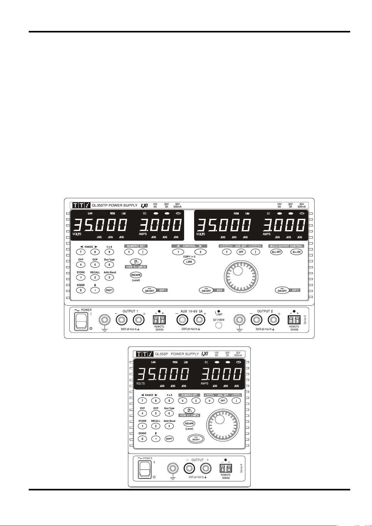
Front Panel Connections 9
Rear Panel Connections 9
Initial Operation 11
Manual Operation 14
Main Outputs 14
Main Outputs – Link Mode (T models only) 21
Main Outputs – Copy Function (T models only) 23
Auxiliary Output (T models only) 23
Remote Operation (P models only) 24
Interface Locking 24
Address & Baud Rate Selection and Interface Status View 24
Remote/Local Operation 25
RS232 Interface 25
USB Interface 26
LAN Interface 26
Status Reporting 30
Remote Commands 34
RS232/USB Remote Command Format 34
GPIB Remote Command Formats 34
Command List 35
Maintenance 40
Note: The latest revisions of this manual, device drivers and software tools can be
downloaded from: http://www.aimtti.com/support.
This manual is 48511-1560 Issue 8
1

Unmatched Precision, Unrivalled Performance
The QL series II provides the highest perform ance levels available in a laboratory power supply.
Voltage and current are controlled using 16 bit DACs enabling voltages t o be set to 1mV resolution
even at full output. Indeed, the accurac y is suff icient for the PSU to be used as a calibration
source for some hand-held DMMs.
The QL series II uses pure linear technology and offers unrivalled perfor m anc e in terms of
regulation, output noise and dynamics. Line and load regulation are c lose t o t he limit of
measurement. Output noise is less t han 350µV r m s in CV mode and down to 20µA rms in CI
mode. Recovery time from transient cur rent pulses is better than 50µs.
It provides full remote sense capability via dedicated sense terminals. Remote sense is ess ent ial
to maintain precise regulation at the load. When remote sense is not req uired, internal local
sensing can be selected at the touch of a but ton.
Multiple Ranges for Greater Flexibility
The QL series II provides multiple ranges for increased cur r ent capability at lower voltages. The
main range offers 0 to 35 Volts at up to 3 Amps (QL355) or 0 to 56 Volts at up to 2 Amps (QL564).
The higher current rang e pr ovides up to 5 Amps for voltages up to 15V (QL355) or 4 Amps for
voltages up to 25V (QL564). A further low current range provides enhanced current set ting and
measurement resolution of 0·1m A.
The product of voltage and current c an be displayed at any time by pressing the VxA button. The
power is displayed to a resolution of 0·01 Watts.
Introduction
Fast, Simple and Safe to use
The user interface of the QL series II has been carefully designed to provide rapid control whilst
guarding against any possibility of error.
Voltage and current setting can be per formed either by direct numeric entry or, for applications
where the voltage or current must be gradually changed, by using t he quasi-analogue Jog control.
To enable the current limit t o be s et before connecting the load, the limit sett ing is displayed when
the output is off. Pressing t he View Limits key at any time provides a temporary display of the limit
values allowing precise adjustment to also be made with the output on.
Setting Memories for Added Convenience
The QL series II provides storage of up to 50 power supply sets-ups in non-volatile memory for
each main output, plus (T models only) a further 50 set-ups for linked mode operation, plus 10 setups for the auxiliary output. Upon mains switch-off, the set -up of the PSU is saved and is
automatically restored at switch-on.
OVP and OCP Trips with 'Alarm' Output
The QL series II provides fully adjustable over-voltage and over-current trips which can be used
both as a fail-safe against acc idental mis-s et t ing and as a protection against inappropriate load
conditions. In addition to turning the out put off, a trip condition switches the rear panel alarm
signal enabling other equipment to be cont r olled.
For complete protection of t he power supply, the trip will also be operated by over-temperature or
excess voltage on the sense terminals.
Auxiliary Output with Fully Variable Vol tage (T models)
The QL series II triple output power supplies incorporate an auxiliary output which is fully variable
between 1 volt and 6 volts to a resolution of 0.01V, and has a current capability of 3 amps.
A front panel button enables to voltage and current for the auxiliary output to be viewed on the
Output 1 display whenever required.
2
Fully Programmable via GPIB, RS232, USB or L AN
The programmable ‘P’ models incorporate a full bus interface permitting remote control and
readback via either GPIB (IEEE-488), RS232, USB or LAN.
The GPIB interface conforms fully with IEEE-488.2 and IEEE-488.1.
The RS232 interface uses a standard 9-pin D-connect or and has a Baud r at e variable from 600
to 19200.
The USB interface is compatible with USB 2.0 and USB 1.x.
The LAN interface is 1.4 LXI Cor e 2011 compliant.
The QL series II uses simple and consistent command struc t ur es which make programming
particularly easy regardless of which interface is used.
An IVI driver for Windows is included. This provides support for common high-level applications
such as LabView*, LabWindows*, and HP/Agilent VEE*.
All power supply settings can be controlled via the bus. Voltage and current can be set to a
resolution of 1mV or 0·1mA (main outputs). Actual voltage and current can be read back
together with the power supply status.
* LabView LabWindows is a trademark of National Instrument s Corp. Agilent VEE is a trademark of Agilent Technologies i nc.
3

Voltage/Current Ranges:
QL355
QL564
0V to 15V/0·001A to 5A
0V to 25V/0·001A to 4A
Accuracy ± (0·03% + 5mV)
Accuracy ± (0·2% + 5mA); ± (0· 2% + 0· 5m A) on 500m A range.
CI indicator lit in constant current mode.
Preset voltage and current limit displayed when Output off.
Duplicate rear panel Output and Sense screw terminals on P models.
load to half load or vice versa.
Speed:
excursion (for resistive load). Excludes command processing t im e.
QL355
QL564
Load
Load
Up
35V 500mA
200ms
40ms
56V/500mA
300ms
60ms
Down
35V 500mA
120ms
600ms
56V/500mA
200ms
800ms
(20MHz bandwidth):
Normal mode current: <0·2mAr m s; <20µArms on 500mA range.
Specification applies for sense lead resistance <0·5Ω.
Current <0·01% + 250µA; <0.01%+ 50µ A on 500mA range.
typically<(100ppm + 0·1mA)/°C on 500mA range.
General specifications apply for the tem per ature range 5°C to 40°C. Accuracy specifications
apply for the temperature range 18°C to 28°C after 1 hour warm-up with no load and calibration
at 23°C. Typical specifications are determined by design and are not guaranteed.
MAIN OUTPUTS
Specification
0V to 35V/0·001A to 3A
0V to 35V/0·1mA to 500mA
Voltage Setting: Resolution 1mV
Current Setting: Resolution 1mA; 0·1mA on 500mA range
Output Mode: Constant voltage or constant current with automatic cross-over.
Output Switch: Electronic, non isolating. Switch illuminated when Output on.
Output T erminals: Universal 4mm safety binding posts on 19mm (0·75”) pit c h for Output;
screwless terminals for Sense.
Transient Response:
Voltage Programming
<50µs to within 15mV of set level for a change in load current from full
Maximum time required for output t o set tle within 1% of its total
Full Load
No
0V to 56V/0·001A to 2A
0V to 56V/0·1mA to 500mA
Full Load No
Up
Up
Down
Down
Ripple and Noise
Load Regulation: For any load change, measured at the output t er m inals, using
Line Regulation: Voltage <0·01% + 2mV for 10% line change.
Temperatur e Coefficient: Voltage: typically <(50ppm + 0·5mV)/° C
15V 5A
35V 3A
15V 5A
35V 3A
Normal mode voltage: <0·35mVrms and 2mVp-p
remote sense.
Voltage <0·01% + 2mV.
Current <0·01% + 250µA; <0.01% + 50µ A on 500mA range.
Add typically 2·5mV for a 0·5V drop in the positive output lead.
Current: typically <(100ppm + 1mA)/°C;
6ms
20ms
6ms
25ms
6ms
7ms
250ms
600ms
25V/4A
56V/2A
25V/4A
56V/2A
10ms
40ms
10ms
50ms
6ms
15ms
400ms
800ms
4

Response time typically 100µs
Response time typically 35ms
Protection Functions:
Output trips off for OVP, OCP, over-temperature and Sense miswiring
Display Ty pe:
5-digit (Volts), 4-digit (Amps), 14mm (0·56") LED.
Accuracy ± (0·1% of reading + 10mV)
Accuracy ± (0·2% + 0·005A); ± (0· 2% + 0· 5mA) on 500mA range
Accuracy ± (0·3% + 0·05W); ± (0·3% + 0·005W) on 500mA range
Voltage Range:
1V to 6V
Accuracy: ± 0.5% ±10mV
Current Limit:
3A minimum
Output Switch:
Electronic, non isolating. Switch illuminated when Output on.
screwless terminals on rear panel.
protection for currents up t o 1A. Over-current tr ip.
(20MHz bandwidth)
Load & Line Regulation:
<1·0% for a 90% load change; 0· 1% for a 10% line change.
(use SET/VIEW button)
Current Meter: Resolution 10mA, accuracy ± 0.5% ±10m A
Speed:
excursion (for resistive load). Excludes command processing time.
1V to 6V: 10ms, no load and full load
6V to 1V: 10ms, no load and full load
Output Protection: Output will withstand forward voltages of up to 20V above rated output
voltage. Reverse protection by diode clamp for currents up t o 3A.
Over-voltage Protection:
(OVP)
Over-current Pr otection:
(OCP)
Range 1V to 40V (QL355), 1V to 60V (QL564)
Resolution 0·1V; accuracy ± (2% + 0·5V)
Range 0·01A to 5·5A (Q L355), 0·01A to 4·4A (QL564)
Resolution 0·01A; accuracy ± (0·2% + 0·01A)
METER SPECIFICATIONS (Main Outputs)
Voltage (CI mode) : Resolution 10mV
Current (CV mode): Resolution 0·001A; 0·1mA on 500mA range
V x A: Resolution 0·01W; 0·001W on 500mA range
AUXILIARY OUTPUT (T models only)
Voltage Setting: Resolution: 10mV
Output T erminals: Universal 4mm safety binding posts on 19mm (0·75”) pit c h. Duplicate
Output Protection: Output will withstand up to 16V forward voltage. Diode clamp reverse
Ripple & Noise:
Status Indication: Current limit lamp. Current overload trip indication.
Meter Specifications:
Voltage Programming
<2mV rms, 10mVp-p
Voltage Meter: Resolution 10mV, accuracy ± 0.5% ±10mV
Maximum time required for output to settle within 1% of its total
KEYBOARD & ROTARY CONTROL
All functions, including the selection and set-up of the remote control interf ac es, c an be set from
the keyboard. The rotary jog control can be used to adj ust output voltage and current settings in
a quasi-analogue mode.
5

General
RS232:
Standard 9-pin D-connector. Variable Baud rat e ( 600 to 19200).
GPIB:
Conforming with IEEE488.1 and IEEE488.2
USB:
Standard USB 2.0 hardware connection. Operates as a virtual COM port.
LAN:
Ethernet 100/10base-T hardware connection. 1.4 LXI Core 2011.
change.
Status Indication:
Remote mode and LAN status indicators
Main Outputs
Voltage Setting:
16-bit; Resolution 1mV, accuracy ± (0·03% +5mV)
Resolution 0.01mA, Accuracy ± (0·2% + 0·5mA) on 500mA range.
Readback V & I
See meter specifications.
Auxiliary Output (T models only)
Voltage Setting:
Resolution 10mV, acc ur acy ± 0. 5% ±10mV
Current Setting:
Resolution 10mA, accuracy ± 0.5% ±10mA
Readback V & I
See meter specifications
Installation Category II
Power Consumption:
Single output: 250VA max; Triple output: 500VA max.
Operating Range:
+5ºC to +40ºC, 20% to 80% RH
Storage Range:
−40ºC to + 70ºC
Environmental:
Indoor use at altitudes up to 2000m, Pollution Degree 2.
output if internal temperat ur es exceed predet er m ined t hr es holds.
interfaces.
instrument via http://www.aimtti.com/support (serial no. needed).
Triple output: 280 x 160 x 290mm (WxHxD), excl. feet & t er m inals
ALARM OUTPUT
Isolated rear-panel open-collector output signal. User can s elect out put to be activated for either
OVP, OCP, Overtemperat ure or Sense miswiring, or for any of those four faults.
DIGITAL INTERFACES (P models only)
Full digital remote control facilities are available through the RS232, USB, LAN and G PI B inter faces.
Remote Command
Processing Time:
Current Setting: 16-bit; Resolution 0.1mA, accuracy ± (0·2% + 5m A)
GENERAL
AC Input: 230V AC or 115V AC ± 10%, 50/60Hz
Typically <25ms between receiving the command terminator for a step
voltage change at the instrument and the out put voltage beg inning to
Cooling: Intelligent variable-speed fan. Over-t em per ature trip shuts down
Store/Recall: Up to 50 set-ups each main output, 50 linked set-ups, and 10 auxiliary
output settings can be saved and recalled via the keyboard or remote
Safety: Complies with EN61010-1 & EN61326-1.
For details, request the EU Declaration of Conformity for this
Size: Single output: 140 x 160 x 290mm (WxHxD), excl. feet & terminals.
Weight: Single: 5.5kg; Triple: 10·5kg
6

l
Safety
This power supply is a Safety Class I instrument according to IEC classification and has been
designed to meet the requirem ents of EN61010-1 (Safety Requirements for Elect r ical Eq uipm ent
for Measurement, Control and Laborator y Use). It is an Installation Category II instrument
intended for operation from a normal single phase supply.
This instrument has been tested in accordanc e with EN61010-1 and has been supplied in a safe
condition. This instruction manual contains some information and warnings which have to be
followed by the user to ensure safe operation and to r etain the inst r um ent in a safe condition.
This instrument has been designed f or indoor use in a Pollution Degree 2 environment in the
temperature range 5°C to 40°C, 20% - 80% RH (non-condensing). It may occasionally be
subjected to temperatures between +5°C and –10°C without degradation of its safety. Do not
operate while condensation is present.
Use of this instrument in a manner not spec ified by these instructions may impair the safety
protection provided. Do not operate the instrum ent outside its rat ed supply voltages or
environmental range.
WARNING! THIS INSTRUMENT MUST BE EARTHED
Any interruption of the mains earth conduct or inside or outside t he inst r um ent will make the
instrument dangerous. Int entional interruption is prohibited. The protective action must not be
negated by the use of an extension cord without a protective conductor.
When the instrument is connected to its supply, terminals may be live and opening the covers or
removal of parts (except those to which access can be gained by hand) is likely to expose live
parts. The apparatus shall be disconnected from all voltage sources before it is opened for any
adjustment, replacement, m aint enance or repair.
Capacitors inside the power supply may still be charged even if the power supply has been
disconnected from all voltage sources but will be safely discharged about 10 m inut es af ter
switching off power.
Any adjustment, maintenance and repair of the opened instrument under voltage shall be
avoided as far as possible and, if inevitable, shall be carried out only by a skilled person who is
aware of the hazard involved.
If the instrument is clearly def ec t ive, has been subject to mechanical damage, excessive
moisture or chemical corrosion the safety protection may be impaired and the apparatus should
be withdrawn from use and returned for checking and repair.
Make sure that only fuses with the required rated current and of the specified type are used f or
replacement. The use of makeshift fuses and the short-circuiting of fuse holders is prohibited.
Do not wet the instrument when cleaning it.
The following symbols are used on the instrument and in this manual:-
Earth (ground) terminal.
mains supply OFF.
mains supply ON.
alternating current (ac)
direct current (dc)
7
BROWN BLUE BROWN BLUEBROWN
115V230V
for 230V operation:
1.6A (T) 250V HBC
for 115V operation:
3.15A (T) 250V HBC
for 230V operation:
4A (T) 250V HBC
for 115V operation:
8A (T) 250V HBC
for 230V operation:
1.6A (T) 250V HBC
for 115V operation:
3.15A (T) 250V HBC
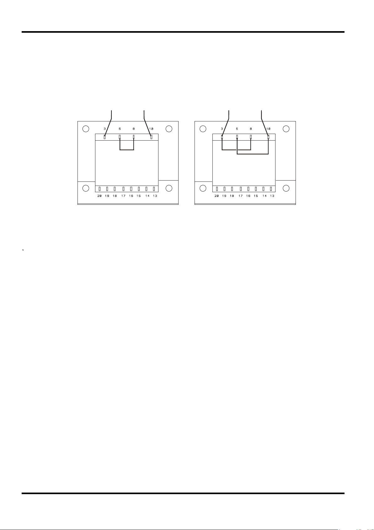
Installation
Check that the instrument oper ating voltage marked on the rear panel is suitable for the local
supply. Should it be necessary to change the operating voltage, proceed as follows:
1) Disconnect the inst r um ent from all voltage sources.
2) Remove the screws which retain the top cover and lift off t he c over.
3) Change the connec t ions on bot h transformers following the appr opriate diagram below:
4) Refit the cover and the secure with the same screws.
5) To comply with safety standard requirements the operating voltage mar ked on the rear panel
must be changed to clearly show the new voltage setting.
6) Change all three fuses to ones of the correct r at ing, see below.
Fuse
The AC inlet fuse is located in the fuse drawer in the lower part of the IEC inlet connector. To
change the fuse remove the line cord and open the fuse drawer with a suitable tool.
QL355, QL355P, QL564 & QL564P
The correct mains fuse t ype is 20 x 5mm 250V HBC time-lag with the following rating:
QL355T, QL355TP, QL564T & QL564TP
The correct mains fuse t ype is 20 x 5mm 250V HBC time-lag with the following rating:
In addition, the two transformer s ar e individually fused inside the power supply. To access these
fuses remove the cover as described above; both f uses are clipped to the small PCB which is
fitted directly onto the pins of t he IEC inlet connector itself.
The correct fuse type is 20 x 5mm 250V HBC time-lag with the following rating:
Make sure that only fuses with the required current r ating and of the specified type are used for
replacement. The use of makeshift fuses and the short-circuiting of fuseholders are prohibited.
8

Mains Lead
Connect the instrument to the AC supply using the mains lead provided. Should a mains plug be
required for a different mains outlet socket, a suitably rated and appr oved mains lead set should be
used which is fitted with the required wall plug and an IEC60320 C13 connector for the instrument
end. To determine the minimum current rating of the lead-set for the intended AC supply, refer to the
power rating information on the equipment or in the Specification.
Any interruption of the mains earth conductor inside or outside the inst rument will make the
instrument dangerous. Intentional interruption is prohibited.
Mounting
This instrument is suitable both for bench use and rack mounting. It is delivered with feet for
bench mounting. The front f eet include a tilt mechanism for optimal panel angle.
A rack kit for mounting QL Series power supplies is available from the Manufacturers or their
overseas agents. The rack will accommodate 1, 2 or 3 single units or a tr iple and single unit; a
blanking piece is also available for unused positions in the rack .
Ventilation
The power supply is cooled by an intelligent multi-speed fan which vents at the rear. Take care
not to restrict the air inlets at the side panels or the exit at the rear. In rack-mounted situations
allow adequate space around the instrument and/or use a fan tray for forced cooling.
WARNING! THIS INSTRUMENT MUST BE EARTHED.
Front Panel Connec tions
The loads should be connected to the positive (red) and negat ive (black ) terminals marked
OUTPUT 1, OUTPUT 2, o r AUX.
Remote sense connections to the loads on Outputs 1 or 2, if required, are made from t he
corresponding positive (+) and negative (−) REMOTE SENSE term inals. Rem ot e s ense
operation is selected from the keyboard or via a remote control interface (P models only); the
REMOTE SENSE lamp is lit when remote sense is selected. Switching off remote sense ret ur ns
the instrument to local sensing at the output terminals.
The terminal marked
is connected to the chassis and safety earth ground.
Rear Panel Connections
Main Output Terminals (P models only)
The output and sense terminals are duplicated on the rear panel screw-terminal block marked
Output +, Output −, Sense + and Sense − ; these connections are paralleled with their front panel
equivalents.
Connections
Remote sense operation is selected from the keyboard or via a remote control interface. When
the rear panel terminals are used, remote sense should always be selected to ensure t hat output
regulation is maintained within specification.
Auxiliary Output Terminals (T models only)
The front panel AUX OUTPUT terminals are duplicated on the rear panel with screwless
terminals marked AUXILIARY OUTPUT.
9

5
GND
Signal ground
9
CD
No internal connection
Alarm Outputs
Associated with each main output are recessed 2-pin connectors marked Alarm. These provide
access to an opto-isolated NPN swit ching transistor, the function of which can be set from the
keyboard, see the Alarm Output section of this manual.
The maximum operating voltage that can be applied across t he t er minals is 20VDC and the
maximum sink current for t he s witch 'closur e' is 1m A.
Do not apply external voltages between the terminals exceeding 30VDC.
RS232 (P models only)
9−pin female D−connector with pin connections as shown below. Can be connected to a
standard PC port using a fully wired 1:1 male-female cable without any cross-over connections.
Pin Name Description
1 RI
2 TXD Transmitted data from instrument
3 RXD Received data to instrument
4 CTS
Passively asserted (+V through 10kΩ)
Signal ground is connected to instrument ground.
USB (P models only)
The USB port is connected to instrument ground. It conforms with USB 2.0 (Full Speed) and
accepts a standard USB cable. The Windows plug-and-play funct ions should aut om at ically
recognise that the instrument has been c onnected. If the correct driver is not found, follow the
Windows on-screen prompts and install the required files from the CD supplied.
LAN (P models only)
The LAN interface is designed to meet 1.4 LXI ( Lan eXtensions for Instrumentation) Core 2011.
. Remote control using the LAN interface is possible using a TCP/IP Socket protocol. The
instrument also contains a basic Web server which provides information on the unit and allows it
to be configured. Since it is possible to misconfigure the LAN interface, making it impossible to
communicate with the instrument over LAN, a LAN Configur ation Initialise (LCI) mechanism is
provided via a recessed switch on the rear panel (marked LAN RESET) to reset the unit t o the
factory default.
Further details are given in the Remote Operation chapter. For more information on LXI
standards refer to www.lxistandard.org/home
6 RTS
Passively asserted (+V through 10kΩ)
7 DSR No internal connection
8 DTR
GPIB (P models only)
The GPIB signal grounds are connect ed to the instrument ground. The implemented subsets are:
The GPIB address is set fr om t he front panel.
10
SH1 AH1 T6 TE0 L4 LE0 SR1 RL2 PP1 DC1 DT0 C0 E2

This section of the manual is a gener al intr oduction to the controls and operation of the
instrument and is intended to be read befor e us ing the power supply for the first time.
In this manual front panel keys, connections and display indicators are s hown in capitals,
e.g. STORE, ESCAPE, OUTPUT, JOG. Messages shown on the 7-segm ent display are printed
in a different type-font, e.g.
characters as they are shown on the 7-segment display.
StorE, GPIb, triP in upper or lower case to represent the
Switching On, Output On/Off
The power switch is located at the bottom left of the front panel.
At power-up the default behaviour is for the instr ument's settings to be restor ed t o those
automatically saved when it was switched off, but with all outputs always off. However, the us er
can change the default setting such that selected outputs are restored at power-up t o their status
at power-down, see the Extra Functions section.
The DC outputs are switched electronically with their respective ON/OFF keys; the k ey
illuminates when the output is on. In addition, all outputs can be switched on and off toget her
using the ALL ON and ALL OFF keys.
Synchronous Output On/Off Switching (T models only)
Pressing ALL OFF at any time will synchronously turn off any outputs that are on; under the same
load conditions outputs will typically turn off within 1ms of each other. With all outputs off the ALL
OFF key is illuminated green. Pressing the ALL ON key when all the outputs are off will turn all
the outputs on synchronously; outputs with identical settings and load conditions will typically turn
on within 1ms of each other. However, if one output is already on, pressing ALL ON will turn the
remaining outputs on but the turn-on delay between the outputs will be up to 80ms, even with the
same output setting and load conditions.
Initial Operation
Keypad
Only the principles of operation are outlined here; the set ting of individual parameters is given in
detail in later sections.
The paramount consideration in designing the user int er face has been to make changing settings
as 'safe' as possible (i.e. with minimal risk of accidentally applying excessive voltages to a target
system) whilst achieving ease of use. This has been achieved by requiring the user to confirm
(OK) new numeric settings, with the option to ESCAPE at any point or even to simply pause until
the operation times-out and the instr um ent r eturns to its original settings.
In addition a buzzer, illuminated keys, LED indicators and display messages prompt, guide or
warn the user such that entry or control error s ar e m inimised. Where some of t hese features
(e.g. beeps or flashing indicator s) ar e c onsider ed unneces sar y by regular user s , the option exists
to disable them, see the Extra Functions section.
On triple output (T) models t he ability to change settings from the k eypad or by using the Jog
controls is assigned to Output 1, Output 2 or both by using the 1, 2 or LINK CONTROL keys
respectively. The key (1 or 2) as soc iated with the selected output illuminates to show which
output is under control. In LINK mode (bot h keys lit) both outputs are controlled at the same
time, including some of the shifted operations (RANGE, STORE, RECALL and V x A). The
further descriptions that follow apply to either or both main outputs as appropriate to the setting
indicated by the illumination of the CONTROL keys.
Under normal conditions the numeric keypad is disabled; pressing any key will cause the buzzer
to make a double beep, indicating an illegal operation. To set a voltage or current with the
keypad press the V or I NUMERIC SET key; the appropriate display shows 0·000V or 0·000A
with the digit to the left of the decim al point flashing. Digits are entered in response to t he
flashing prompt, together with the decimal point at the appropriate time, and t he ent r y is
confirmed with the OK key. If OK is not pressed within 10 seconds of the last numeric key the
entry is cancelled and the display returns to its original setting. I f ESCAPE is pressed anywhere
in the entry procedure, entry is cancelled and the display returns to its orig inal setting.
11

The OK key is used to confirm m ost keypad entries. At all other times it becomes the VIEW V/I
LIMITS key and pressing it will cause the display to show preset output voltage and current limit
for 3 seconds; during this per iod t he LI M indicator in the display flashes.
Pressing SHIFT illuminates the key and gives the numeric keys the functions marked above them
(e.g. STORE, RECALL, etc.). When a function is selected by pressing one of these keys SHIFT
is cancelled (the SHIFT key is no longer lit). The further key presses required to complete the
selected function are described in detail in the sections that follow; if no key is pressed within 10
seconds to complete the function, t he function will terminate as if ESCAPE has been pressed.
SHIFT is a toggle key; pressing SHIFT again when it has been selected will cancel SHIFT.
SHIFT is also cancelled by ESCAPE, or by pressing SET V or SET I. Note that in LINK mode
settings accessed by STORE and RECALL are specific to the LINK mode and are in addition to
settings accessible when STORE and RECALL are used on individually selected outputs.
Jog Control
The rotary 'jog' contr ol per m its the output voltage or current limit to be incremented or
decremented in steps with a resolution set by the JOG SET keys; the output im m ediat ely f ollows
the setting, i.e. no OK is required.
At power-up jog is always off. To jog the voltage or current setting press the V or I JO G SET key;
the key will illuminate and the JOG indicator under the digit that was last j ogged will flash. Whilst
the V or I JOG SET key is lit, each furt her pr es s of the V or I key moves the JOG indicator one
digit to the left; the selection ' wraps-round' suc h t hat when the largest value of jog increment has
been reached the next press returns it to t he lowest. The def ault posit ion at power-up is under
the LSD, i.e. the lowest jog increment is select ed.
Turning the rotary jog control clockwise/anti-clockwise increments/decrements the selected digit;
digits to the left of the one being jogged are automatically incremented/decrem ent ed when the
decade overflow/underflow point is reached. Digits to the right of the one being jogged r em ain
unchanged unless the jog step overf lows/underflows the range maximum/minimum in which case
they are set to zero. On the QL355, for example, 33·65V goes to 34·65V goes to 35·00V for the
35V range and a 1V jog increment; 0· 160A goes to 0·060A goes to 0·001A for a 0·1A jog
decrement.
The jog steps that can be selected for the main range are 1mV, 10mV, 100mV and 1mA, 10mA,
100mA; if the 500mA range has been selected the current increment st eps are 0· 1m A, 1m A,
10mA.
To disable the jog r otar y contr ol pr ess the JOG SET OFF key; reselecting JOG SET V or I will
enable jog on the last used digit position. Jog is not cancelled by using numeric entry or any of
the SHIFT functions but it is disabled whilst that function is enabled.
When in constant voltage mode, with the output on, the right-hand display will show actual
current rather than curr ent limit . If JOG SET I is selected the JOG indicator under the selected
digit will flash at h a lf-speed ('lazy' flash). To obser ve the effect of jogging the current limit it will
be necessary to either turn the output off (so that the display permanently shows the current limit)
or to press VIEW V/I LIMITS which causes the current limit to be displayed until 3 seconds after
movement of the jog cont r ol ceases . The 'lazy' flash is also used when JOG SET V has been
selected and actual voltage is being shown because the supply has gone into current limit.
The factory default is t o flash the JOG indicator under the selected digit for the whole time that
jog is selected so that the user is cons tantly reminded which parameter can be incr em ent ed/
decremented. Where this degree of reminding is consider ed inadeq uate the user can select,
using the Extra Functions capability, to flash the digit itself; conversely, where the flashing is
considered intrusive the user can select to not f lash t he JOG indicator (except when the 'lazy'
flash is shown).
12
 Loading...