

Page 1

MX100T & MX100TP
Triple Output Multi-Range DC Power Supply
INSTRUCTION MANUAL
Page 2

CONTENTS
1 Product Description ......................................................................................................4
2 Safety .............................................................................................................................5
3 Installation .....................................................................................................................6
3.1 Mains Operating Voltage ..........................................................................................6
3.2 Mains Lead ...............................................................................................................6
3.3 Mounting ...................................................................................................................6
3.4 Ventilation .................................................................................................................6
4 Connections ..................................................................................................................7
4.1 Front Panel Connections ..........................................................................................7
4.2 Rear Panel Connections (MX100TP) .......................................................................7
4.3 Terminal Voltages and Safe ty...................................................................................7
4.4 Output Protection ......................................................................................................7
5 Initial Operation .............................................................................................................8
5.1 AC Power On/Off ......................................................................................................8
5.2 DC Output On/Off .....................................................................................................8
6 The Display and Soft Key Control ...............................................................................9
6.1 The Home Screen ....................................................................................................9
6.2 Individual Output Screens ........................................................................................9
6.3 Setting with the Keypad .......................................................................................... 10
6.4 Setting with the Spin Wheel .................................................................................... 10
6.4.1 Spin Wheel Action Options ...................................................................................10
7 Power Supply Settings ............................................................................................... 11
7.1 CV and CC modes, Viewing Settings (Limits)......................................................... 11
7.2 Setting with Individual Output Screens ................................................................... 11
7.3 Power Display (VxA) ............................................................................................... 12
7.4 Selecting Current Meter Averaging ......................................................................... 12
7.5 Setting Over-Voltage and Over-Current protection ................................................. 12
7.6 Setting the Voltage/Current Range ......................................................................... 13
7.7 Store and Recall of Settings ................................................................................... 13
7.8 The System Menu Screen ...................................................................................... 14
7.9 Voltage Tracking ..................................................................................................... 14
7.10 Locking the Front Panel ...................................................................................... 14
8 Display Symbols ......................................................................................................... 15
9 Menu - Advanced Functions ...................................................................................... 16
9.1 Setting Voltage Tracking ........................................................................................ 16
9.2 Current Meter Averaging Setup .............................................................................. 17
9.3 Store and Recall of Settings for All Outputs ........................................................... 17
9.4 Multi-On / Multi-Off Operation and Sequencing ...................................................... 17
9.4.1 Emergency Off ......................................................................................................18
9.5 Pass Code Locking of the Front Panel ................................................................... 18
9.6 System Preferences ............................................................................................... 19
9.7 Setting to Factory Defaults ..................................................................................... 19
9.8 Adjusting LCD Contrast .......................................................................................... 19
9.9 Calibration .............................................................................................................. 19
9.10 Remote Control Interfaces (MX100TP only) ........................................................ 19
Page 1
Page 3

10 Changing System Preferences ............................................................................... 20
10.1 Status at Power-up .............................................................................................. 20
10.2 Alert Sound (Beep) .............................................................................................. 20
10.3 Spin Wheel Action ............................................................................................... 20
11 Notes on Operation .................................................................................................. 21
11.1 Accuracy and Resolution ..................................................................................... 21
11.2 Remote Sense .................................................................................................... 21
11.3 Parallel Wiring of Outputs .................................................................................... 21
11.4 Series Wiring of Outputs ..................................................................................... 22
11.5 Instantaneous Current Output ............................................................................. 22
11.6 Output On/Off and Response Speed ................................................................... 22
11.7 Using OVP and OCP ........................................................................................... 23
11.7.1 OCP Trip at Output On .........................................................................................23
11.8 Over-temperature Trip (OTP) .............................................................................. 23
12 Remote Interface Operation (MX100TP only) ........................................................ 24
12.1 MX100TP Rear Panel Connections..................................................................... 24
12.2 Remote Interface Configuration .......................................................................... 24
12.2.1 GPIB Interface ......................................................................................................25
12.2.2 RS232 Interface ....................................................................................................25
12.2.3 USB Interface and Devic e Driver Installation ........................................................26
12.2.4 LAN Interface ........................................................................................................26
12.2.5 LAN IP Address and Hostname ............................................................................27
12.2.6 Interface Locking ..................................................................................................28
12.2.7 Status Reporting ...................................................................................................29
13 Remote Commands (MX100TP only) ...................................................................... 34
13.1 General ............................................................................................................... 34
13.1.1 Remote and Local Operati on ................................................................................34
13.1.2 Remote Command Handling .................................................................................34
13.1.3 Remote Command Formats ..................................................................................34
13.1.4 Command Timing..................................................................................................35
13.1.5 Response Formats................................................................................................35
13.2 Command List ..................................................................................................... 35
13.2.1 Instrument Function Com mands ...........................................................................35
13.2.2 Common Commands ............................................................................................37
13.2.3 Status Commands ................................................................................................38
13.2.4 Interface Management Commands .......................................................................39
14 Maintenance ............................................................................................................. 40
14.1 Cleaning .............................................................................................................. 40
14.2 Fuse .................................................................................................................... 40
14.3 Calibration ........................................................................................................... 40
14.4 Firmware Update ................................................................................................. 40
15 Technical Specifications ......................................................................................... 41
16 Default Values .......................................................................................................... 44
Page 2
Page 4

1 Using this Manual
This manual includes cr os s references which are shown as fol lows - see section X.X.
Within a PDF file, the shaded number is a hyperlink to that section number which enables the
user to jump rapidly to the sect i on r eferred to and then jump back to c ontinue reading the
original section.
(N.B. for hyperlink navigation within Acrobat Reader , enable “show all page navigati on tools” or
use the keyboard shortcut s Alt+Left-Arrow and Alt+Right -Arrow).
The Table of Contents is also fully hyperlinked and is replicated within the Bookmarks pane.
Note: The latest revisio ns of this manual, device drivers and s oftware tools can be
downloaded from: http://www.aimtti.com/support or http://www.aimtti.us/support
This manual is 48511-1610 Issue 5
(USA).
Page 3
Page 5
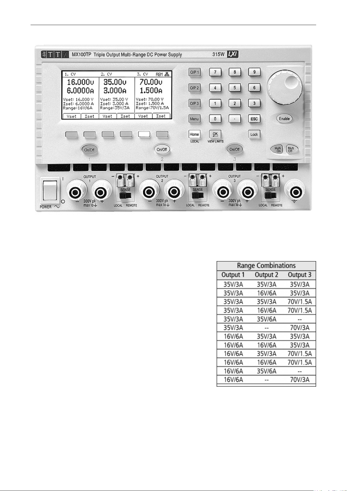
2 Product Description
The MX100T is a triple output l aboratory power supply incorp or ating three outputs of similar
power and features.
Each output can provide 0 to 35 volts at 0 to 3 amps (105 watts) with range switching extending
its capabilities to prov ide voltages up to 70V and currents up to 6A. Twelve range combinations
are available as shown in t he c har t.
Mixed-mode r egulation is used which com bines switchmode power conversion with linear final regulation to give
good noise and transient performance.
All information is displayed on a large backlit graphic LCD
and control is via soft keys together with a numeric keypad
and spin wheel.
Advanced features inclu de 50 settings memories for each
output plus 50 further memories that record the settings for
all three outputs together.
Multi-On and Multi-Off keys supplement the individual output
On/Off keys and can be programmed to turn the outputs on
or off in a timed sequence.
The front panel can be locked t o pr ev ent accidental changes
to settings.
The power supply is housed in a compact half-rack width, 3U high c as e with front input
ventilation. An intelligent fan is used to minimise coolin g nois e.
The MX100TP has the sam e manual control features and adds USB, RS232, GPIB and LXI
compliant LAN interfaces together with duplicate power and sense terminals at the rear.
Page 4
Page 6

3 Safety
meaning Caution. In this manual this symbol is used to highl ight situations where
Earth (ground) terminal.
mains supply OFF.
l
mains supply ON.
alternating current (ac )
This power supply is a Safety Class I instrument according to IEC classification and has been
designed to meet the requirements of EN61010-1 (Safety Requirements for Electrical Equipment for
Measurement, Control and Laboratory Use). It is an Installation Category II instrument intended for
operation from a normal single phase supply.
This instrument has been tested in accordance with EN61010-1 and has been supplied in a safe
condition. This instruction manual contains some information and warnings which have to be
followed by the user to ensure safe operation and to retain the instrument in a safe condition.
This instrument has been designed for indoor use in a Pollution Degree 2 environm ent in the
temperature range 5°C to 40°C, 20% - 80% RH (non-condensing). It may occasionally be subjected
to temperatures between +5°C an d –10°C without degradation of its safety. Do not oper ate while
condensation is present.
Use of this instrument in a manner not specified by these instructions may impair the safety
protection provided. Do not operate the instrument outside its rated supply voltages or
environmental range.
WARNING! THIS INSTRUMENT MUST BE EARTHED
Any interruption of the mains earth conductor inside or outside the instrument will make the
instrument dangerous. Intentional interruption is prohibited. The protective action must not be
negated by the use of an extension cord without a protective conductor.
When the instrument is connected to its supply, terminals may be live and opening the covers or
removal of parts (except those to which access can be gained by hand) is likely to expose live parts.
The apparatus shall be disconnected from all voltage sources before it is opened for any
adjustment, replacement, maintenance or repair. Capacitors inside the power supply may still be
charged even if the power supply has been disconnected from all voltage sources but will be safely
discharged about 10 minutes after switching off power.
Any adjustment, maintenance and repair of the opened instrument under voltage shall be avoided
as far as possible and, if inevitable, shall be carried out only by a sk illed person who is aware of the
hazard involved.
If the instrument is clearly defective, has been subj ect t o mechanical damage, excessive moisture or
chemical corrosion the safety protection may be impaired and the apparatus should be withdrawn
from use and returned for checking and repair.
Make sure that only fuses with the required rated current and of the specified type are used for
replacement. The use of makeshift fuses and the short-circuiting of fuse holders is prohibited.
Do not wet the instrument when cleaning it.
The following symbols are used on the instrument and in this manual:-
incorrect use may either damage the instrument or cause a potential hazard to the
user.
Page 5
Page 7

4 Installation
4.1 Mains Operating Voltage
This instrument has a univers al input range and will operate from a nominal 115V or 230V
mains supply without adjustment. Check that the local supply meets the AC Input requirement
given in the Specification see section 17.
4.2 Mains Lead
Connect the instrum ent to the AC supply using the mains lead pro vid ed. Should a mains plug
be required for a different mains outlet socket, a suitably rated and approved mains lead set
should be used which is f itted with the required wall plug and an IE C60320 C13 connector for
the instrument end. To determine the minimum current rating of the lead-set for the intended
AC supply, refer to the power rating information on the equipment or in the Specification.
WARNING! THIS INSTRUMENT MUST BE EARTHED.
Any interruption of the mains earth conductor inside or outsid e the instrument will make the
instrument dangerous. I ntentional interruption is prohibited.
4.3 Mounting
This instrument is s ui table both for bench use and rack mounting. It is delivered with feet for
bench mounting. The f ront feet include a tilt mechanism for optimal panel angle.
A rack kit for mounting in a 19” rack i s available from the manufacturers, or their agents and
distributors overseas.
4.4 Ventilation
The power supply is cooled by an intelligent multi-speed fan which vents at the rear. Cooling
air is drawn in through slots in t he front panel directly above the terminals, and by slots in the
base of the unit close to the front.
In a rack-mounted situation no additional space is required above or to the sides of the unit.
Some air space below the unit will ensure the best possible airflow and the lowest fan speeds
for a given power, but is not required.
Ensure that the ventilation slots and rear fan exhaust are not obstructed. In the event of
overheating, a temper ature trip will turn all of the outputs off – see section 11.8.
Page 6
Page 8
5 Connections
5.1 Front Panel Connec tions
For each output, the load should b e connected to the positive (red) and negative (black)
terminals marked OUTPUT.
Both are fully floating and either can be connected to ground or t o a terminal of another output.
Remote sense connections to the load, if required, are made from the positive (+) and negati v e
(-) SENSE terminals. Switch the SE N S E switch to REMOTE when remote s ens ing i s r equired.
Switch back to LOCAL when remote sensing is not in use. See section 11.2 for more
information.
The grey terminal marked with an Earth symbol is connected to the chassis and safety
earth ground.
5.2 Rear Panel Connections (MX100TP)
The MX100T has only an AC power connection socket on t he r ear panel. The MX100TP has
duplicate power and sense terminals on the rear panel and offers full remote control capabilities
through USB, RS232, GPIB and LAN interfaces.
All interfaces are full y isolated from the power supply output terminals. USB, RS232 and G PIB
interfaces are connected to chassis ground. The LAN interface is isolated by standard network
transformers.
Rear connections for t he MX100TP are detailed in section 12.1.
5.3 Terminal Voltages and Safety
The outputs of the power supply are fully floating and may connected to other equipment resulting in
the voltage appearing at a terminal being greater than the output voltage alone.
The maximum permissible voltage between any terminal and earth ground ( ) is 300VDC;
the maximum permissible voltage between either terminal of one output and either terminal
of another output on the same power supply is also 300VDC.
WARNING! Such voltages are exceedingly hazardous and great care should be taken by the user.
The front terminals are intrinsically touch proof, but hazard may still exist depending upon the type
of connection made to the terminal. On no account should the connections be touched under such
use.
For the MX100TP only, voltages appearing on the front terminals will als o appear on the
rear terminals. The rear terminals have protective walls but are not intrinsically touch proof,
and additional precautions must be taken if voltages above 70 volts DC could be present.
If any hazardous voltages could exist, all connections to the front or rear terminals must be m ade
with the power switched off on all voltage sources.
5.4 Output Protect ion
Each output is protected agains t the application of external forward voltages up to 50 volts
(outputs 1 and 2) and 90 volts (output 3). Each output is protected agai ns t the application of
reverse voltages by a clamp diode with a maximum conti nuous c urrent capability of 3 amps.
Further protection is provided by OVP and OCP trips and an over-temperature trip.
Page 7
Page 9

6 Initial Operation
6.1 AC Power On/Off
Power ~ O/I
The AC power switch is located at the bottom left of the front panel.
At power-up a screen is displa ye d that shows the firmware revis i on number and a brief
description of the starting conditions. These can be changed from System Pref er enc es if
required – see section 10.1.
6.2 DC Output On/Off
On/Off
Each output has its own DC On/Off key. These are positioned direc tly above
each set of output terminals and are numbered 1, 2 and 3 from left to ri ght.
Alternate presses of the key turns the output on or off. The on stat e is
indicated by the key being illuminated in red.
At power-up the default beha viour is for all the outputs to be s et to off.
However, the user can change thi s default setting such that t he outputs are
restored to their condition when the instrument was switched off. This change is made from
System Preferences - see section 10.1.
Multi-O n / Multi-Off
It is also possible to turn all three outputs on or off simult aneously
using the Multi-On and Multi-Off keys. By default these keys operate
on all three outputs simult aneously but the behaviour can be changed
to turn the outputs on or off i n a timed sequence or to remove an
output from either Mult i-On or Multi-Off control, see section 9.4.
Page 8
Page 10
7 The Display and Soft Key Control
With the exception of output On/Off, the primary control of the
power supply is via the six ke ys dir ec tly below the display.
These are referred to as “soft keys” because their function is not
fixed but is annotated by legends on the display directly above.
The function of the keys depends upon the type of screen selec ted. There are five
main screens which are s el ec ted by the keys to the right of the di s play. The
selected key is illuminated.
The main screen (Home) displays all t hr ee outputs simultaneously, the system
menu screen (Menu) provides ac c es s to advanced functions, and the individual output screens
(O/P n) show more detailed inform ation for each individual output.
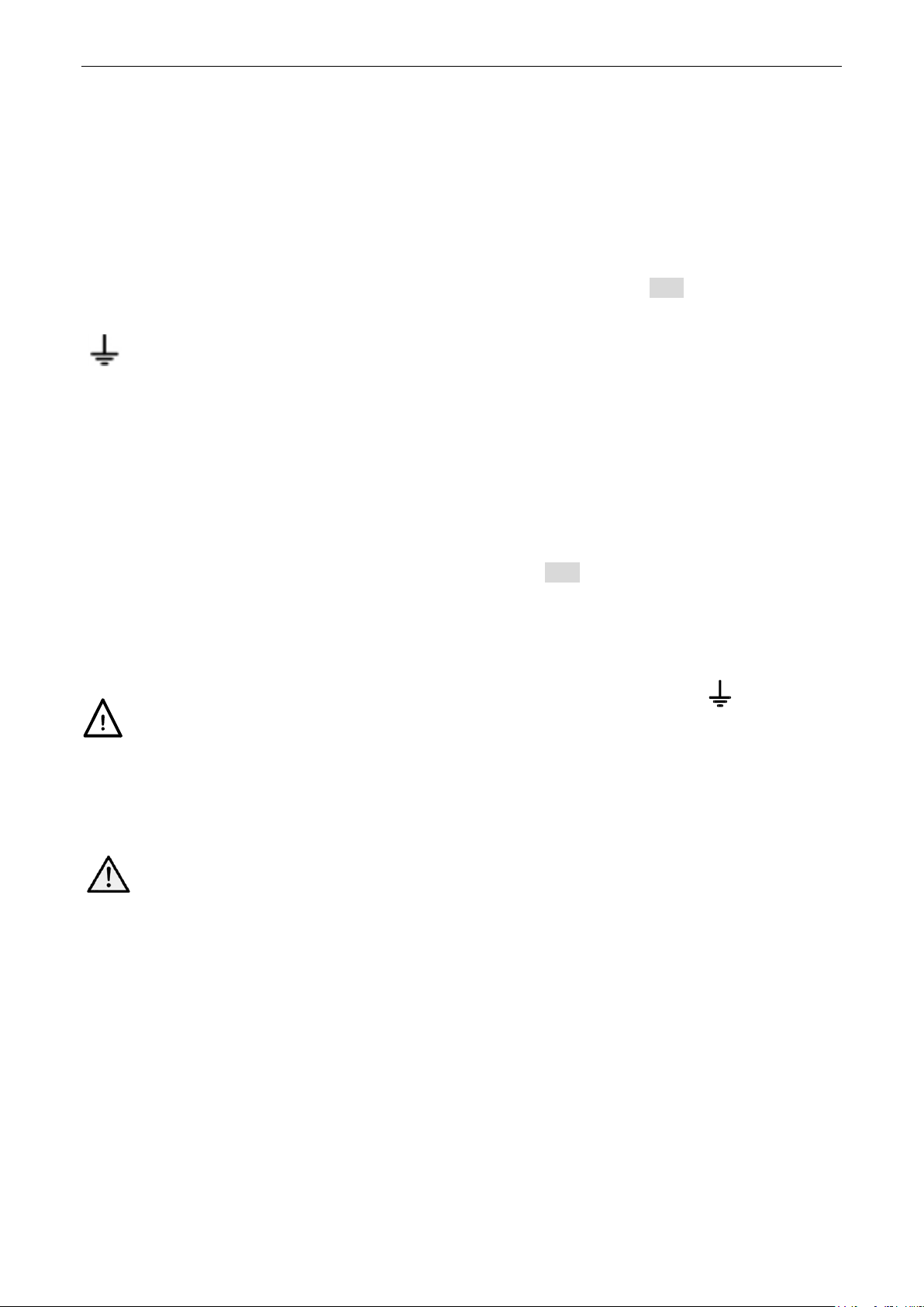
7.1 The Home Screen
The main (Home) screen is selected
with the key marked Home and shows
the primary information for all three
outputs simultaneousl y whilst enabling
voltage and current to be set for any
output.
The display is divided in to three
sections representing outputs 1, 2 and
3 from left to right. For each output
the display shows operat ing mode on
the top line as CV (constant voltage), CC (constant curr ent) or SET (Settings). SET is
displayed when the output is off.
The two meters directly below show the set values for voltage and current when the output is
off, and the voltage and cur r ent being supplied to the load when the output is on.
With an output on, the three lines below the meters show the set volt age (Vset), the set current
(Iset) and the output range (Range). If the output is off, the Vset and Iset lines do not appear
(because the meters are showing the set values).
The six soft keys are used to set
voltage (Vset) or current (Iset) for
each of the outputs. The presently
selected output and parameter (V or I)
is indicated by illuminat i on of the soft
key and by a flashing arrow in front of
the parameter to be adjusted. The
user can move freely between setting
voltage or current for any out put by
pressing the appropriate k ey.
Pressing the same key again or
pressing ESC (Escape) cancels the
key and disables all sett ing capability.
7.2 Individual Output Screens
Each output has its own display screen selected with t he keys O/P 1, O/P 2 and O/P 3. The
selected key is illuminated.
These enable additional parameters and functions to be controlled for that output including
Range, OVP & OCP, memory store & recall (Stores), and current meter averaging (Iavg).
These are detailed withi n s ection 7.
Page 9
Page 11

7.3 Setting with the Keypad
Vset & Iset
Voltage or current can be set using the numeric keypad.
Upon pressing a numeric k ey, the OK key will start to flash. When the
numeric value entry is completed, pressing OK causes the va l ue to be
accepted and actioned. E ntry can be abandoned at any point by
pressing ESC (Escape). The new value being entered is shown directly
below the meters in a sm aller font size.
Entry is in volts or amps to a res olution of 0.001 volts and 0.0001 amps for output 1, and 0.01
volts and 0.001 amps f or out puts 2 and 3.
Entries need only to be completed as far as the desired digit of resolution, e.g. to enter 5.000
volts it is only necessary to ent er 5 followed by OK.
7.4 Setting with the Spin Wheel
Vset & Iset
Voltage or current can alternatively be set using the spin wheel. The
wheel is disabled by default but can be enabled by pressing the ke y
below it which toggles its action on or off. When enabled the key is
illuminated. The wheel changes the output settings immediately, no OK
confirmation is required.
The wheel has a non-linear action. If it is moved slowly the value is
incremented in minimum steps (1mV/0.1mA for output 1, or 10mV/1mA
for outputs 2 or 3). When the wheel is r otated more rapidly the rate of
increment is increased enab li ng the value to be changed quickl y.
7.4.1 Spin Wheel Action Options
The action of the spin wheel can be c hanged from System Prefer enc es
to reduce the speed-related increment rate if preferred. Three choices are available: Normal
(default), Reduced acceleration, or Single Digit Increment.
Making changes is described in section 10.3.
Page 10
Page 12
8 Power Supply Settings
The procedures for set ting voltage and current, either numerically or via the spin wheel, have
been explained in the previous s ec tion.
8.1 CV and CC modes, Vi ewing Settings (Limits)
Depending upon the load conditions, the actual voltage and ac tual current applying t o the load
will not both be equal to t hei r s et values.
Output On – CV Mode
When in constant voltage mode the output voltage is equal to t he set value and CV is shown on
the top line of the display. The c urrent setting represents the limiting value of current that coul d
flow (the current limit).
Output On – CC Mode
When in constant current mode the output current is equal to the set value and CC is shown on
the top line of the display. The volt age setting represents the limiting value of voltage that could
be applied (the voltage limit).
Switch-over between CV and CC modes oc c urs automatically dependent upon t he l oad
conditions and the settings. The voltage and current settings may also be described as limits
since they represent the maximum values that can apply at the loa d.
To draw attention to the CC s ymbol and make it clear at a glance, a f lashing arr ow is
placed next to it. It is also possible to set an audible aler t – see section 10.2.
Output Off
When an output is off, the meters show these set values and SET is shown on the top line of
the display. When an output is on, the values of voltage generate d and current flowing are
shown together with CV or CC.
View Settings/ View Limits
It is also possible to view the set values for all three outputs at any time. Pressing the OK key
(also marked View Limits or V iew Settings) causes the display to change so that the meters all
show the limits values for a period of about 2 seconds.
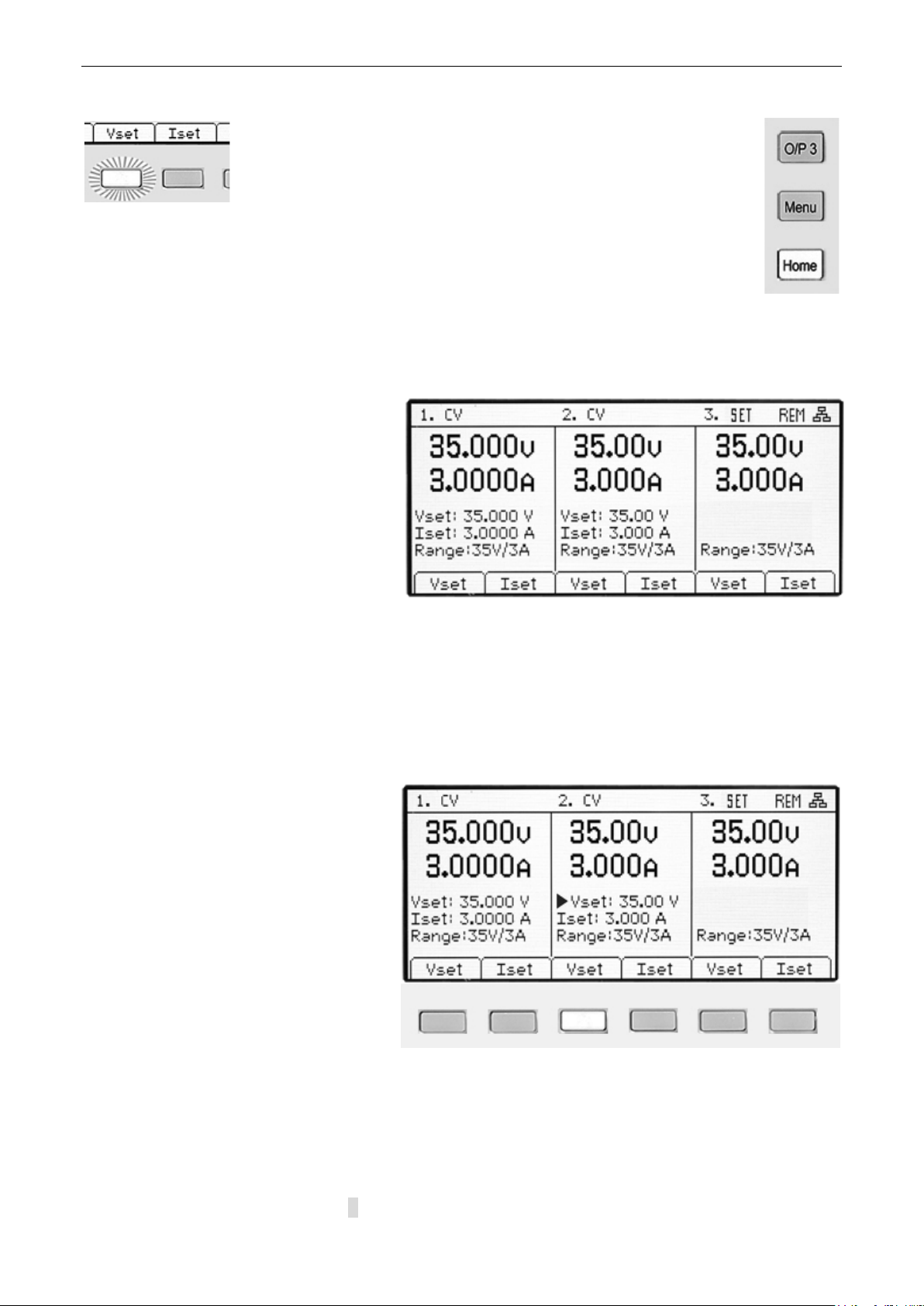
8.2 Setting with Individual Output Screens
The three illuminated k eys marked
O/P 1, O/P 2 and O/P 3 select a
screen that controls only the chosen
output. This screen provides more
information than the main (Home)
screen (see section 6.1), and allows
additional param eters to be set.
The top line shows the operating
mode (CV, CC or SET) together with
the voltage tracking status . The
meters are displayed in a larger font, and the complete sett ings status for the output is shown
below them.
The six soft keys are used to set voltage and current (Vset and Iset), over-voltage and overcurrent protection levels (OVP & OCP), current meter averaging (Iavg), range selection (Range)
and store or recall of settings (Stores).
Setting voltage or current is as previously described for the Home screen – see section 6.1.
Page 11
Page 13
8.3 Power Display (VxA)
The power being supplied to the load (VxA) is displayed in watts on the lower right hand side.
The value is calculated from the metered values of voltage and current and is displayed with a
maximum resolution of 0.001 watts f or output 1 and 0.01 watts for outputs 2 and 3.
8.4 Selecting Current Meter Averaging
Iavg
Current meter averaging is us eful when the load current is varying rapidly. It can help to reduce
the variation in the reading and make the display easier to foll ow.
Selection is done from each individual output screen. Pr es s i ng the soft key
marked Iavg toggles curr ent meter averaging on or off. The pres ent status is
shown in the area above the key and by a n asterisk ( s symbol) appearing
directly after the curr ent meter. This symbol is also displayed on the Home
screen.
Three levels of averaging representing low, medium or hi gh c an be s el ected from the System
Menu - see section 9.2. The default value is medium.
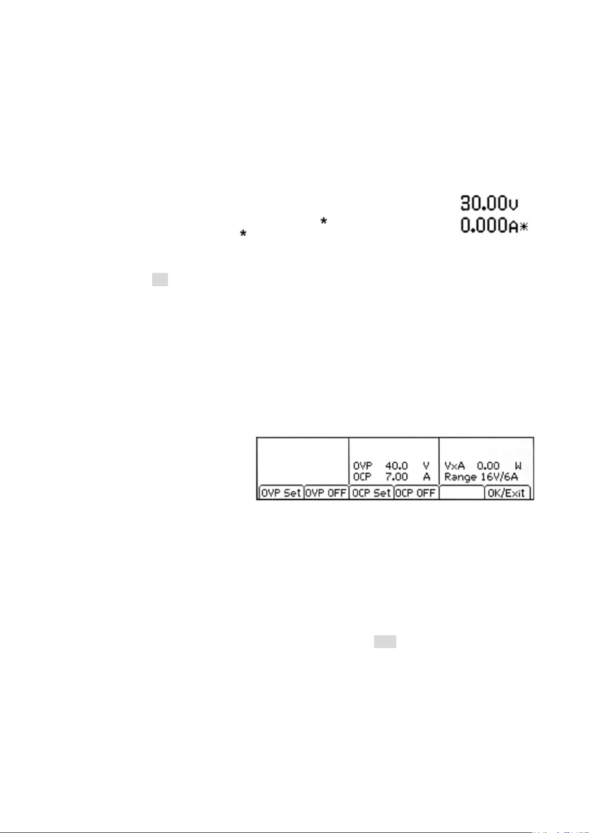
8.5 Setting Over-Voltage and Over-Current protection
OVP/OCP
The power supply offer s user adjustable over-voltage protec tion (OVP) and over-current
protection (OCP). If a voltage is detected that exceeds the O V P level, or a current is detected
that exceeds the OCP level, the output is switched off and the message OVP or OCP is
displayed.
OVP is adjustable between 1V and 40V for outputs 1 and 2, and between 1V and 80V for
output 3. OCP is adjustable bet ween 0.01A and 7A for outputs 1 and 2, and between 0.01A
and 3.5A for output 3.
Pressing the OVP/OCP soft key
creates a new set of soft keys from
which OVP & OCP values can be set
or turned on or off.
Pressing OVP Set causes the key to
illuminate and makes the OVP value settable. A new value can be entered us ing the numeric
keypad or by the spin-wheel if enabled. OVP can be turned off by pressing OVP OFF, and
turned back on by pressing OVP On. The previous OVP value is retained when OVP is off and
is displayed in brackets.
Similar capabilities ar e pr ov i ded for controlling OCP.
Note that, when set to OFF, the f unc tion is not completely disabled but is set to the maximum
value for the output. Thus if OVP was set to OFF on output 1 and an external voltage greater
than 40V was applied to the terminals, an OVP trip would occur.
More information on using OV P and OCP is provided in section 11.7.
Page 12
Page 14

8.6 Setting the Voltage /Current Range
Range
Each output has more than one range. For output 1 the choice is 35V/3A or 16V /6A. For
output 2 the choice is 35V/3A , 16V/6A or 35V/6A. For output 3 t he c hoice is 35V/3A, 70V/1.5A
or 70V/3A.
Note that selecting 35V/6A on output 2 will disable output 3, and selecting 70V/3A on output 3
will disable output 2.
Pressing the Range soft k ey brings
up a menu screen which shows t he
currently selected range by
illumination of the soft key. Pressing
another key selects a ne w range
which is actioned when OK/Exit is
pressed.
Note that a change of range can only be made when the output is off. If the output is on, a
message will prompt the user to turn it off.
8.7 Store and Recall of Settings
Stores
Each output has 50 memor y stores
capable of storing range, volt age,
current, OVP and OCP. Pressing t he
Stores soft key brings up a m enu
screen which shows the present
contents of the memor ies f r om which
settings can be stored or recalled.
The memories are numbered from 00
to 49 with the currently selected line
highlighted. The locati on can be
scrolled using the spin wheel or stepped through using the arrow keys. It is al s o pos sible to
jump directly to a location by entering a two digit number ( e.g. 07 or 45). Unused memory
locations are shown by the word Empty.
Pressing the Store key writes the present settings of the out put into the selected memory
location. If the position alr eady has settings stored within it a confirmation is required.
Pressing the Recall key tr ansfers the stored settings of the sel ec ted memory location to the
output. This happens immediately that the Recall key is pres s ed. Note that, if the recalled
range is different fr om the present r ange, the output will be automatically turned off.
The contents of a particular loc ation can be deleted by pressing the Delete soft key. A
confirmation is required.
From the Delete confirmation screen it is also possible to delet e the contents of all 50 locations
by pressing Del All. A conf irmation is required.
Store and Recall for Multiple Outputs
It is also possible to store and r ecall settings for all three out puts simultaneously. This is
described in Advanced Func tions section 9.3.
Page 13
Page 15

8.8 The System Menu Screen
The operation of the System Menu sc r een i s selected with the key marked Menu
which illuminates when pr essed.
System menu functions are described within section 9 - A dvanced Functions.
8.9 Voltage Tracking
The power supply can be set -up such that the voltage of output 2 tracks that of
output 1, or that output 3 trac k s output 2, or that outputs 2 and 3 both track output
1. The tracking status is shown on the top line of the display. Voltage tracking is
selected from the Syst em Menu, see section 9.1.
8.10 Locking the Front Panel
Lock
The front panel can be “locked” such that the power supply will not respond to any
key presses. This is in order to pr ev ent an accidental changes to settings.
Pressing the Lock key disables the front panel. This is indic ated by the key being
illuminated in green. Onc e locked any key press creates a warning mes s age on the display.
To unlock the front panel, pres s and hold the Lock key for more than one second.
For additional security it is also possible to lock the fr ont panel using a pass-code. This is
explained in Advanced Functions section 9.5.
Page 14
Page 16

9 Display Symbols
Some functions are indi c ated by symbols or abbreviation on the display as follows:
Function Home Screen Individual Output S c r e e n
Output on, constant voltage
mode
Output on, constant current
mode
Output off SET shown on the top line
Current meter averaging on symbol after current meter symbol after current meter
Voltage tracking TRK > shown on top line
Multi-On/Multi-Off not set to
defaults (set to Delayed or
Never)
Power supply under rem ote
control (MX100TP only)
LAN connection status
(MX100TP only)
Note that the LAN symbol changes to reflect the connection status. This is detailed within the
Remote Control pages - see section 12.2.4.
CV shown on the top line next
to the output number
CC shown plus flashing ar r ow
next to the output number
next to the output number
between the Master and Slave
Clock symbol on top line next
to the mode indication
for the affected output
REM shown at top right hand
side
LAN symbol shown at top
right hand side. (see not e)
CV shown on the top line
CC shown plus flashing ar r ow
on the top line
SET shown on the top line
(and Iavg ON in small font)
V Track ON or OFF shown on
top line plus Master or Slave
Clock symbol on top line
REM shown at top right hand
side
LAN symbol shown at top
right hand side (see note)
The example screen opposite shows
output 1 in constant current (CC)
mode, output 2 in constant voltage
(CV) mode and output 3 sho wing
settings (output off).
Output 3 is set to track output 2, and
outputs 2 and 3 have Multi-On/MultiOff not set to defaults.
Output 3 current meter has aver aging
turned on.
Page 15
Page 17
10 Menu - Advanced Functions
Menu
Pressing the key marked Menu selec ts the System Menu screen.
This provides access to advanced options and functions. When the system menu is
displayed, setting of output parameters is not possible but operation of the output
On/Off keys is unaffect ed.
Each item of the system menu is selected by using the two arrow keys, or by turning
the spin wheel until the desir ed line is highlighted, and then pressing the Select soft
key. This selects a menu scr een r elating to the function selec ted.
Help Text
Alternatively, pressing the Help soft
key provides some on-screen
explanation of the highlighted function.
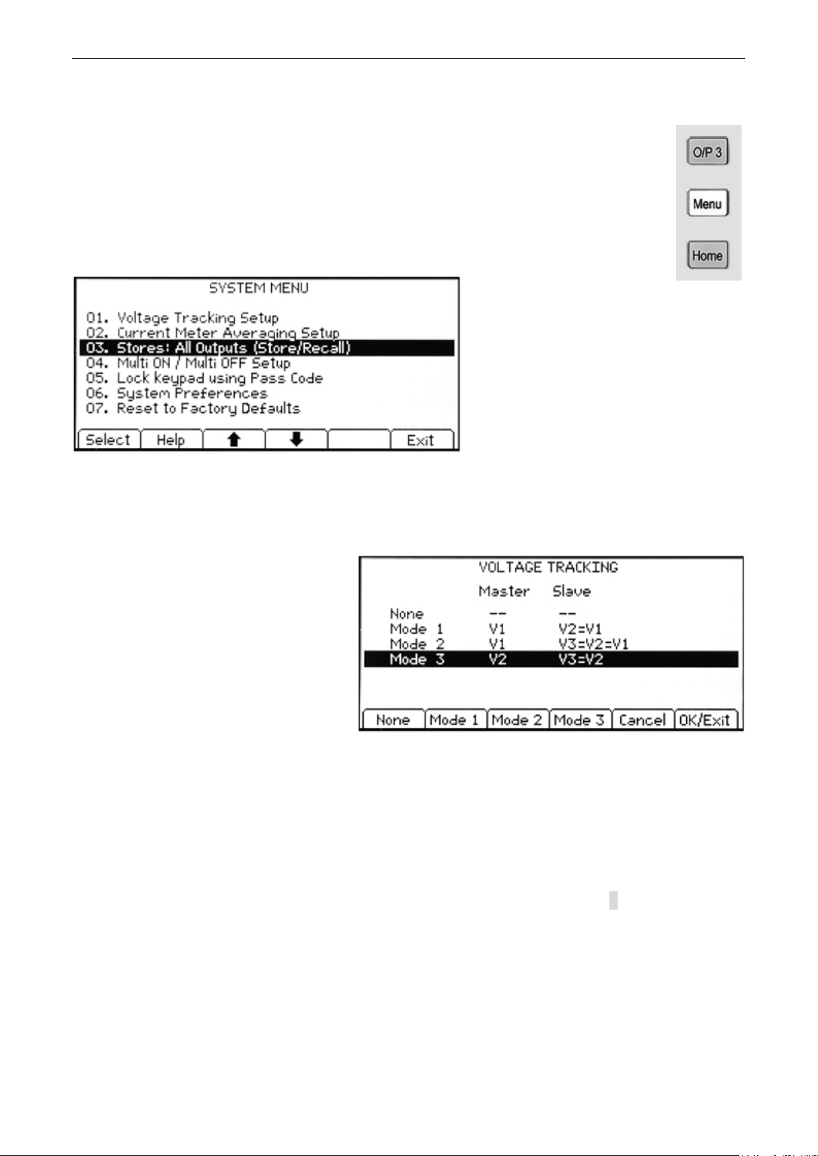
10.1 Setting Voltage Tracking
Menu > Voltage Tracking Setup
By default all three output s are
completely independent . However, it
is possible to make the volt age of an
output always equal to the volt age set
on another output. This is c al led
voltage tracking.
Tracking voltages can be useful in
setting up adjustable vol tages of equal
or opposite polarity, or when outputs
are wired in parallel or in series.
Three alternative volta ge tracking arrangements ar e possible:
Mode 1 Output 2 tracks Output 1.
Mode 2 Output 2 and Output 3 both track Output 1.
Mode 3 Output 3 tracks Output 2.
The controlling output is described as Master, whilst a controlled output is described as Slave.
Voltage tracking can only be selected when the voltage range for the Slave output is equal to or
higher than that of the Master output.
The tracking condition is displayed on the top line of the dis play, see section 8.
When tracking is set, changing the range of either the Master or Sla ve o utput will cancel
tracking regardless of the direction of the change.
Page 16
Page 18
10.2 Current Meter Averaging Setup
Menu > Current Meter Averaging Setup
The degree of averaging of the current meter reading when Iavg is turned on (see section 7.4)
can be set individually for eac h output.
The System Menu function “Curr ent Meter Averaging Setup” provides an individual choice of
low, medium or high (Low, Medium , High) for each of the three outputs set via t he s oft keys.
The default value is medium.
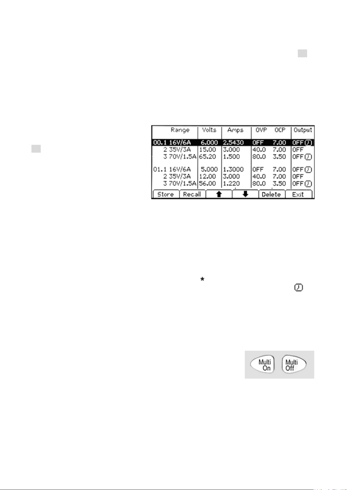
10.3 Store and Recall of Settings for All Outputs
Menu > Stores: All Outputs (Store/Recall)
Each output has its own set of 50
memories in which settings c an be
stored for that output ( see section
7.7). A further set of 50 m em ories is
provided that allow the user to store
and recall the settings status for all
three outputs simultaneous ly.
Unlike the individual memories, which
store only Range, Volts, Amps, and
OVP/OCP, these memories also store
the output ON/OFF state, current meter averaging state, and the Multi-On/Multi-Off settings.
The System Menu function “Stores: All Outputs (Store/Rec all)” creates a screen similar t o the
Stores screen for the individual outputs, but with an extra col umn for ON/OFF. The thr ee
outputs are listed on successive rows.
The output On/Off state is i nc luded in order to allow memor ies to be recalled in sequence
including the turning of outputs on or off. Note that recalling a memory will override the existi ng
On/Off state and this should be considered when setting up the power supply prior to storing
each status entry.
Current meter averaging being set on is indicated by the symbol after the set curr ent value.
Multi-On/Multi-Off settings other than bot h set to Quick are indicated by a clock s ymbol
after the On/Off stat e.
Note that output delay sett ings are only applied when the Multi-On/Multi-Off function is used
and not when a memory is recalled.
10.4 Multi-On / Multi-Off Operation and Sequencing
Menu > Multi-On/Multi-Off Setup
The two keys on the bottom r ight hand side marked Multi-On and
Multi-Off control the On and Off behaviour for al l three outputs.
By default these keys provide a synchronous On/Off capability
whereby all three outputs are turned on or turned off simult aneous ly
by pressing a single key.
The System Menu function “Multi-On/Multi-Off Setup ” enables the operation of these keys to be
changed to suit the user’s requi r ements. Delays between the s witchi ng of the outputs can be
introduced to create an On or Off sequence, and any individual output can be excluded from
Multi-On or Multi -Off control.
Page 17
Page 19

At ex-factory default s, the On and Off
delays are all set to Quick c ausing
them to respond immediately to the
key press. The Tab arrow keys move
through the On and Off states for the
outputs which can be changed using
the soft keys.
Delay sets a time value in millisec onds between 10ms and 20,000m s (20 seconds)
using the spin wheel.
Never removes an output complet ely from control by the Multi-On or Multi-Off key.
Quick returns to immediate response.
Note that any previously set delay value is retained when set to Quick or Never and is restored
when Delay is selected agai n.
When any of the settings is other than Quick, a clock symbol is displayed on the t op l ine of
the main (Home) display, and of the individual output screen(s) to which it appli es .
Note that the set delays appl y only to the initiation of an output bei ng turned on or turned off.
The actual delay will depend up on the slew-rate limited tur n-on or turn-off times applying to a
particular output and its l oad. See section 11.6 for more information.
For short delay sequences, the key will flash briefly when pressed. For longer delays it will
continue to flash until t he s equence is completed. Where t he longes t delay is below
approximately 250ms, the key may not flash at all.
10.4.1 Emergency Off
When an Off sequence that includes long delays is in progress, a s ec ond pr ess of the Multi-Off
key will turn all three output s off immediately, including any outputs omitted from the sequence
(i.e. set to Never). Thus a double pres s (or press and hold) of the Multi-Off key will immediately
turn off all the outputs regardless of the sequence settings.
The individual output On/Off keys also remain active during a s equence and can be used to
override a delay.
10.5 Pass Code Locking of the Front Pane l
Menu > Lock Keypad using Pass Code
In addition to the norm al locking of
the front panel (see sect i on 7.10) it is
also possible to lock the front panel
securely by setting a pass code. This
might be appropriate when t he power
supply is installed withi n a system
where, once set up, changes must
only be made by the installer.
The pass code is a “once only” code.
After the system has been unlocked,
the pass code is discarded and a n ew code (or the same one) must be entered in or der to lock
it again.
In the event that the user forgets the pass code, the power supply can be unlocked using the
master pass code of 7835 which is always active.
Page 18
Page 20

10.6 System Preferences
Menu > System Preferences
Various aspects of the power supply operation can be chan ged from the System Preferences
function. These are detailed in section 10.
10.7 Setting to Factory Defaults
Menu > Facto ry Defaults
This function can be used to return most of the instrument settings including Voltage, Current,
Range, OVP, OCP, Output On/Off, Current Meter Averaging, Multi-On/Off Action and System
Preferences back to t he fac tory default values as listed in section 18.
The Store memories f or both i ndividual outputs and All Outputs are unaffected. To clear each
bank of Stores it is necessar y t o us e the function Stores > Delete > Del All.
LCD contrast setting and remote interface settings (MX100TP only) are also unaffect ed.
10.8 Adjusting LCD Contrast
Menu > Adjust LCD Contrast
The LCD contrast can be adjusted over a wide range. The setting is displayed numerically as a
percentage. The displa y can also be inverted from black on white to white on black.
10.9 Calibration
Menu > Calibration
The Calibration function enables the instrument to be r e-calibrated when required.
Calibration will overwrite the exist i ng settings and should only be carr ied out by qualified
personnel in conjunction with the instrument Service Guide and the necessary precision
equipment.
A 4-digit pass code can be set to prevent unauthorised calibration if required.
10.10 Remote Control Int erfaces (MX100TP only)
Menu > Remote Control Interfaces
Settings for the GPIB and LAN interfaces can be observed usi ng this function.
Details for the GPIB interface are within the Remote Interfaces Configuration section 12.2.1.
Details for the LAN interface are within the Remote Interfaces Configuration section 12.2.4.
Page 19
Page 21

11 Changing System Preferences
Menu > System Preferences
Access to System Preferences is
selected from the main system menu.
A listing of system preferences is
shown.
The current system preferenc es are
indicated by ticks against the relevant
setting. Changes are made b y
moving the highlight with either the
arrow keys or the spin wheel and
pressing the Select soft key.
Alternatively a line can be selected directly by entering the two digit number from the keypad.
11.1 Status at Power-up
Outputs at power up / Settings at power up
At power-up the default beha viour is for all the outputs to be s et to Off. However, the user can
change this default sett i ng s uc h that the outputs are restored to their condition when the
instrument was powered down.
The default behaviour als o r eturns the settings (set volts, s et current, range etc.) to those t hat
existed at power-down. This can be changed so that the settings are al ways at factory defaults
(see section 18). This includes all outputs being set to Of f.
11.2 Alert Sound (Beep)
Set beep / Disable beep
An alert sounder is incor por ated that produces a “beep” un der s pecific conditions.
By default a beep will be sounded when an illegal key entry is m ade, or when a trip condition
occurs. This can be disabled if pref erred.
It is also possible for a beep to be sounded whenever an output chang es i nto constant current
(CC) mode. This is disabled by default.
11.3 Spin Wheel Action
Spin wheel action
The action of the spin wheel can be c hanged to reduce the speed-related inc rement rate.
Three choices are available: normal (default), reduced acceleration, or single d igit increment).
Page 20
Page 22

12 Notes on Operation
12.1 Accuracy and Resolution
All three outputs provide good ac c ur acy and resolution and offer remote sensing to ensure
precise regulation at the load. See section 17 for accuracy specifications.
Output 1 offers greater resolution and accuracy than outputs 2 and 3 and uses 5 digit meters to
give 1mV and 0.1mA resolution ( as against 10mV and 1mA for outputs 2 and 3). Consequently
output 1 should be chosen to power circuits where particular ly high precision is required.
12.2 Remote Sense
Each output has a very low output impedance, but this is inevit ably increased by the resistance
of the connecting leads and the contact resistance between terminals and leads. At high
currents this can result in s i gnificant differences between the indicated source voltage and the
actual load voltage (two 20 milliohm connecting leads will drop 0.2V at 5 Amps, for exam ple) .
This problem can be minim i s ed by using short, thick, connecting leads, but where necessary it
can be completely overc ome by using the remote sense capabil ity.
This requires the sense t erminals to be connected to the output at the load instead of at the
source by inserting wires into the SENSE terminals and connec ting them directly to the load.
The switch should then be set to REMOTE instead of LOCAL.
To avoid instability and transient response problems, care must be taken to ensure good
coupling between each output and sense lead; this can best be done by twisting the leads
together. An electrolyti c c apacitor directly across the l oad c onnec tion point may also be
beneficial.
The voltage drop in each output lead should not exceed 0.5 Volts. Higher voltage drops could
result in small metering errors or an inability to supply full power to the load when approaching
maximum voltage and current.
12.3 Parallel Wiring of Outputs
If currents above 6 amps are r equired, this can be achieved by wiring two or more outputs in
parallel. For example, outputs 1 and 2 could be paralleled to provide 16V/12A. In this situation
it would be appropriate to us e vo l tage tracking (Mode1 V2=V1 in this example) so that the
voltage can be adjusted directly on one output. See section 9.1 .
The drawing shows a parallel c onnec tion of two outputs using loc al or remote sensing.
Page 21
Page 23

12.4 Series Wiring of Outputs
If voltages above 70 volts are required, this can be achieved by wiring two or more outputs i n
series. For example, outputs 1, 2 and 3 could be series connected to pr ov ide up to 140V.
Voltages up to 115V could be achi eved by connecting all three outputs in series and selecting
voltage tracking so that full voltage adjustments can be made using one output control.
The drawing shows a series connect ion of two outputs using local or r emote sensing.
Warning! Voltages above 70Vdc are hazar dous live according to EN 61010-1 and
great care must be taken when using the power supply at voltages abo ve thi s level.
Ensure that the exposed end of any wires are fully inserted and inaccessible to the
touch. Always make connections to the power supply with the outputs off.
See also the information regarding t erminal voltages and safety within section 4.3.
12.5 Instantaneous Current Output
The current setting control can be set to limit the continuous out put current to levels down to the
milliamps. However, in common with all precision bench power s upplies, a capacitor is
connected across the output to maintain stability and good tr ansient response.
This capacitor charges to t he output voltage and short-circuiting of the output will produce a
current pulse as the capacitor discharges which is independent of the current limit setting.
12.6 Output On/Off and Response Speed
The output On/Off cont rol of the power supply is entirely electronic . The Off condition is
achieved by setting the voltage to zero and the current level t o low. There is no physical
disconnection of the output s.
When an output is turned on or of f there is a delay between the key being pres s ed and the
output voltage or current goi ng to zero (off) or rising to the set voltage or current (on).
The delay is a function of the loop response time of the power supply and of the stability
capacitor which is placed ac ross the output terminals. This c apac i tance has to be charged or
discharged before the out put can reach the set voltage or return t o zero respectively.
Because bench power supplies are used primarily in CV (constant voltage) mode, the following
explanation applies to CV mode. The situation for CC mode is differ ent.
When switching on, the out put will normally rise to the s et value within a fixed length of time,
typically a few milliseconds (see section 17 – Specifications). However this time c oul d be
Page 22
Page 24

increased if the current s etting is very low or is very close to the c ur r ent required by the load. A
large external capacitance at the load could also slow down the response.
When switching off with no load, the output will normally fall bac k to zero within a fixed length of
time (see section 17 – Specifications). If a load is connected t he response may be quicker
because of the additional dis c harge provided by the load. Ho wever, if the load includes a large
capacitance the respons e may be slower.
Turn-on and turn-off speeds are particularly relevant to Multi -On/Multi-Off output sequencing
(see section 9.4) where delays between the switching of different outputs can be set to a
resolution of 10ms. T hese delays apply only to the initiation of an output being turned on or
turned off, the actual delay will depend upon the actual turn-on or turn-off times applying as
described above.
In situations where the us er needs to know the actual response speeds for specific conditions it
will be necessary to observe this us ing an oscilloscope.
12.7 Using OVP and OCP
OVP (over-voltage protection) monit or s the voltage on the output terminals and switches the
output off if it exceeds the OVP setting. The response speed is typically 100us. Control of OVP
is described in section 7.5.
OVP might be used to guard agains t accidental mis-setting of the power supply, or might be
used to identify a fault conditi on when operating in constant current mode. Unlike the voltage
limit setting, exceedin g the OVP will turn the output off in a situation where damage to the
device under test might otherwise occur.
OCP (over-current protec tion) monitors the current flowing at the output and switches the output
off if it exceeds the OCP sett ing. The response speed is <0.5s. Control of OCP is described in
section 7.5.
OCP might be used to guard against accidental mis-setting of the power supply, or might be
used to identify a fault conditi on when operating in constant voltage mode. Unlike the current
limit setting, exceedin g the OCP will turn the output off in a situation where damage to the
device under test might otherwise occur.
12.7.1 OCP Trip at Output On
If the OCP level is set to a very low level whilst also bein g bel ow the set current level, it is
possible for a trip condition to be created when the output is s witc hed on. This is caused by the
current needed to charg e the output capacitance. Whether a trip occurs is a function of the
OCP trip response speed, the OCP level, the set current and the set output voltage.
12.8 Over-te mperature Trip (OTP)
The power supply has a sensor that monitors the internal ambient temperature. Should that
exceed a safe level, as might occur if the ventilation input or output was blocked, an overtemperature protect ion trip (OTP) will occur. Should O TP occur, all three outputs will be tur ned
off and an OTP message will appear on t he s creen.
Normal operation can onl y be restored by turning the AC supply (Power) off, rectifying the
ventilation problem and allowing the unit to cool bef or e switching back on.
In addition, there is a temperature sensor on the power device of the PFC (power factor
correction) stage. If this detects an over-temperature problem, all power outputs will shut down;
the auxiliary supply f or the CP U and di splay will, however, remain active, and the ‘Hardware
Failure or Over-temperature’ message screen will be dis played. If poor ventilation is suspected,
correct the problem, al low the instrument to cool, and use the Reset soft-key to re-initialise the
instrument. However, if the ‘Hardware Failure or Over-temperature’ message screen continues
to be displayed after the ins trument has cooled and been restar ted, there may be a component
fault; if in doubt, the unit should be returned for service.
Page 23
Page 25

13 Remote Interface Operation (MX100TP only)
13.1 MX100TP Rear Panel Connections
Output Connections
The Output and Sense terminals are duplicated on the rear panel terminal block marked
Output +, Output -, Sense + and Sense -. These connections are paral leled with their front
panel equivalents.
Switch the front panel LO CAL/REMOTE switch to REMOTE when remote sensing is required.
When the rear panel output terminals are used, the use of remote sense is always
recommended to ensure that output regulation is maintained within specification; connections
can be made to either the front or the rear remote sense terminals but never to both pairs of
terminals at the same time. Switch back to LOCAL when remote s ens ing is not in use.
Interface Connecti ons
Interface connectors for USB, RS-232, LAN and GPIB are m ounted on the rear panel. These
are described in detail within the following sections.
13.2 Remote Interface Configurati on
The MX100TP model can be remotely controlled via its RS232, US B, GPIB or LAN interfaces.
The GPIB interface provides full facilities as described in I E E E Std. 488 parts 1 and 2.
The RS232 interface communicates directly with a st andar d COM port.
The USB interface enumerates as a Communications Class device and interacts with
application software through a standard virtual COM port device driver on the PC. The
instrument firmware can be updated in the f ield via t he USB port; see Maintenance, section
16.4 .
Page 24
Page 26

The LAN interface is designed to meet LXI (Lan eXtensions for Instrumentation) version 1.4 LXI
Core 2011. Remote control using the LAN interface is possible using the TCP/IP Socket s
protocol. The instrument also contains a basic W eb server which provides information on the
unit and allows it to be configured from a web browser. Simple command line control from the
browser is also possible.
13.2.1 GPIB Interface
The standard GPIB interface 24-way connector is located on the instrument rear panel. The pi n
connections are as specified in IEEE Std. 488.1-1987 and the inst r ument complies with both
IEEE Std. 488.1-1987 and IEE E Std. 488.2-1987.
It provides full talker, l is tener, service request, serial poll and parallel poll capabilit ies. There are
no device trigger or cont roller capabilities. The IEEE Std.488.1 interface subsets provided are:
S H 1, AH1, T6, L4, SR1, RL2, PP1, DC1, DT0, C0, E2.
The GPIB address of the unit is s et from the system menu:
Settings can be changed f r om the System Menu (Menu > Remote Cont r ol Interfaces). The
present GPIB address is dis played. To change the address, use the spin-wheel to set the
desired address and then press the OK/Exit soft key.
The interface will operate with any commercial GPIB interface card, using the device drivers
and support software prov ided by the manufacturer of that card.
13.2.2 RS232 Interface
The 9-way D-type serial interface connec tor is located on the instrument rear panel. It should be
connected to a standard PC port preferably using a fully wired 9 way 1:1 male-female cable
without any cross-over connections. Alternatively, a 3 way cable can be used, connect ing only
pins 2, 3 and 5 to the PC, but with links made in the connector at the PC end between pins 1, 4
and 6 and between pins 7 and 8, as s hown in the diagram:
Most commercial cables provide these connections.
In addition to the transm i t and rec eive data lines, the instrument passively asserts pins 1 (DCD)
and 6 (DSR), actively drives pin 8 (CTS) and monitors pin 4 (DTR) from the PC. This allows the
use of a fully wired 9-way cable.
The Baud Rate for this instr ument is fixed at 9600; the other parameters are 8 data bits, no
parity and one stop bit. Flow control uses the XON/XOFF prot oc ol , but because of the low
volume of data associated with this instrument it is very unlikely that flow control will actuall y be
invoked.
Page 25
Page 27

13.2.3 USB Interface and Device Driver Installation
The instrument firmware can be updated in the field through the US B port. This does not need
the driver described her e. It requires a PC software utility provided by the manufact ur er, and
uses a HID driver that will already be installed on the PC. If that is the only USB functionality
required, download the pac k age containing the firmware update together with the PC utility from
the manufacturer, and follow the instructions included.
Using the USB interface for remote control requires a Communications Device Class driver on
the PC to provide a virtual COM port instance. In Windows a suitable driver is provided by
Microsoft, but it is not installed by default. The data (.INF) file to control the installation is
provided on the Product Documentation CD delivered with t he unit; however the same driver is
also used by many other instr uments from this manufactur er and may already be known to the
PC.
To install the driver f or the first time, first switch the unit on, and then connect the USB port to
the PC. The Windows plug and play functions should automatically recognise the attachment of
new hardware to the USB interface and (possibly after searching the internet for some time)
prompt for the location of a suitable driver. Follow the Windows prompts and point to the CD,
then the sub-directory for this product, and then to the USB Driver sub-directory below that. The
file is named USB_ARM_VCP_x xx.INF, where xxx is a version number. (A readme.pdf file will
also be found in that director y if further assistance is needed.)
In some cases Windows will not complete this procedure (especial ly recent versions which
search the internet first, looking for the unique Vendor ID and Pr oduct ID), in which case the
instrument will show in Device Manager as “not working properl y”. If this happens, select this
device, right click and choos e “update driver software...” and then “browse this com puter for
driver software...” and t hen loc ate the .INF file on the CD as descr ibed above.
Once Windows has installed the d evice driver it will assign a CO M port number to this particular
unit. This number will depen d on previous COM port assignments on this PC, and it may be
necessary to use Device Manager to discover it. Each instrument has a unique USB identif i er
which is remembered by the syst em, so it will receive the same COM port number whenever it
is attached to the same PC (r egar dl es s of the physical interfac e socket used), even though the
COM port will disappear while the instrument is disconnect ed or switched off. Other instruments
will receive different COM port numbers.
Note that a different PC will not necessarily assign the same COM port number to a particular
instrument (it depends on the history of installations ) , however Device Manager can be used to
change the assignments given.
This virtual COM port can be driven by Windows applications (inc l uding a terminal emulat or ) i n
exactly the same way as any standard COM port, except that the Baud rate and other settings
are unnecessary and are ignored. Some old applications might not function with COM port
numbers 3 or 4, or above 9. In this case, use Device Manager to change the allocation given.
Once it is installed, the driver will be maintained by Windows Update in the usual way.
13.2.4 LAN Interface
The LAN interface is designed to comply with the LXI standar d vers ion 1.4 LXI Core 2011 and
contains the interfaces and protocols described below. For more information on LXI st andards
refer to www.lxistandard. org .
When powered up and attached t o a network, the unit will by default attempt to obtain IP
address and netmask sett i ngs via DHCP, or, if DHCP times out ( aft er 30 seconds ) , via Auto-IP.
In the very unlikely event that an Auto-IP address cannot be found a static IP address is
assigned; the default is 192.168.0.100, but this can be changed on the web page. Connecting
via a router is recommended as this is significantly quicker to assign an IP address; connecting
directly to a PC will only begin t o assign an Auto-IP address after the 30 second DHCP timeout.
Page 26
Page 28

Since it is possible to mis c onfigure the LAN interface, m ak ing i t impossible to communicate with
then the LAN status indicator is .
and
display becomes
the instrument over LAN, a LA N C onfiguration Initialise (LCI) mechanism is provided via a push
switch (marked LAN RESET) accessible thr ough a small hole in the rear panel. T hi s r estores
the default configurati on with DHCP enabled, so the unit will then follow the sequence
described in the previou s paragraph. Note that resetting t he LA N i nterface removes any
password protection.
The progress of establis hing a LAN connection can be viewed either by inspecting the Remote
Control Interfaces screen (Menu > Remote Control Interfaces) or by int er preting the symbol
shown on the status line of t he Home screen, which has four possible indications:
No LAN
Configuring The unit has det ec ted a LAN connection but is not yet c onfigured, e.g. is
LAN OK The LAN connec tion is now configured and the unit can communicate. The
LAN FAULT The unit has detected a problem with LAN conn ection, e.g. Its IP address is in
If the unit cannot detect any connec tion to a LAN, e.g. the cable is unplugged,
waiting for DHCP. The LAN status indi c ator is animated, flashing between
use by another device. Communication is not possible and the display shows
13.2.5 LAN IP Address and Hostname
To communicate with the inst rument through the LAN interface, the IP address (which was
allocated during the con nec tion procedure described abo ve) must be known. Once connected
and correctly configured, the IP address of the unit is displayed within the Remote Control
Interfaces screen (Menu > R emote Control Interfaces). Alternatively the address can be
obtained from the DHCP server, or by using the LXI Discovery Tool des c r i bed below.
mDNS and DNS-SD Support
The instrument supports these multicast name resolut ion protocols, which allow a meaningful
host name to be assigned to the unit without needing an entry in the database of a central
nameserver. The desired hos tname can be entered on the webpage (whic h will have to be
accessed by IP address t he first time); spaces are not allowed. The name then appears in the
.local domain (e.g. myMX100.local), if the accessing de vice is configured to support the
protocol (which is the case with most modern PCs). The default name is followed by the serial
number.
ICMP Ping Server
The unit contains an ICMP serv er allowing the instrument to be ‘pinged’ using its IP address as
a basic communication check , or by its host name if name resolution i s working.
Web Server and Configuration Password Protection
The unit contains a basic web server. This provides information on the instrument and allo ws it
to be configured. The Configure and Instrument Control pages c an be password protected to
deter unauthorised changes to the remote operation conf iguration; the default configuration is
‘no password’. The Configure page itself explains how to set t he password. The password can
be up to 15 characters long; not e that the User Name should be left blank. The password and
hostname will, however, be reset to the default (no password) if the rear panel LAN reset switc h
is used to reset all the LAN parameters to their factory default.
LAN Identify
The instrument's main web page has an 'Identify' function which allows the user to send a
command to the instrum ent which causes its display to flas h until the command is cancelled.
Page 27
Page 29

LXI Discovery Tool
This tool can be used to display the IP addresses and other associated information of all
connected devices that comply with the VXI-11 discovery prot ocol. It is a Windows PC
application, which is provided on the supplied CD ROM that can be installed and run on the
controlling PC, with the uni t either connected directly to the PC network connector or via a
router. Double clicking on any entry in the list of discovered de vices will open the PC's web
browser and display the Home page of that device. For a later version of the tool that supports
discovery by both VXI-11 and mDNS visit www.lxistandard.or g . There are also tools for LA N
discovery included as part of the National Instruments Measurement and Automation E xplorer
package and the Agilent V ee appli c ation.
VXI-11 Discovery Protocol
The instrument has very limited support of VXI-11 which is sufficient for the discovery protocol
and no more.
It implements a Sun RPC Port-mapper on TCP port 111 and UDP port 111 as defined in
RFC1183. The calls supported are:
NU LL, GET PORT and DUMP.
On TCP port 1024 a very simple V X I-11 protocol is implemented, suff ic i ent only for instrument
discovery. This impl em ents the following calls:
CREATE LINK, DEVICE_WRITE, DEVICE_READ and DESTROY_LINK.
Once a link has been created anyt hing written to the device is ignor ed and any attempt to read
from the device returns t he same identification string as the *IDN? query.
V ISA Resource Name
Because of the limited suppor t for VXI-11 (Discovery Protocol only), the instrument must be
referred to by its raw socket information when used with software packages which communicate
using a VISA resource name. For example, an instrument at IP address 192.168.0.100 would
normally have a VISA resourc e name of "TCPIP0::192.168.0. 100::inst0::INST R" but for this
instrument the nam e must be modified to read "TCPIP0::192.168.0.100::9221::SOCKET" where
9221 is the TCP port used by this inst r ument for control and monit or i ng, see below.
XML Identificat ion Document URL
As required by the LXI standard, the instrument provides an XML identification document that
can be queried via a GET at “htt p://IPaddress:80/lxi/identification” that conforms to the LXI XSD
Schema (available at http://www.lxistandard.org/InstrumentIdentification/1.0
XML Schema Standards ( http://www.w3.org/XML/Schema ). This document describes t he
instrument. The hostname can be used instead of the IP address if name resolution is working.
TCP S ockets
The instrument uses 2 sockets on TCP port 9221 for instrument control and monitoring. Text
commands are sent to this port as defined in ‘Remote Commands’ and any replies are returned
via the same port. Any command string must contain one or mor e c omplet e c om mands.
Multiple commands may be separ ated with either semicolons “;” or line feeds. No final
terminator is required, s i nc e the TCP frame implies a term i nator, but one may be sent if desired.
) and the W3C
13.2.6 Interface Locking
All the remote interf ac es are live at all times, to remove any need to select the active interface
and to ensure that the LAN interface is always available (as demanded by the LXI standard). To
reduce the risk of the instr ument being inadvertently under t he c ontrol of two interfaces at once
a simple lock and release mechanism is provided in the instruction s et. The lock is
automatically release d where it is possible to detect disc onnec tion, or when the Local key is
pressed. Access to the interfaces may also be restricted using t he web pages.
Any interface may request to have exclusive control of the instrument by sending an “IF LOCK
1” command. The lock may only be released by sending an “IFLO CK 0” command from the
Page 28
Page 30

interface instance that currently has the lock, and m ay be queried from any interface by sendi ng
an “IFLOCK?” command. The reply to this query will be “-1” if the lock is owned by another
interface instance, “0” if the interface is free and “1” if the lock is owned by the requesting
interface instance. Sending any command from an interface without control privileges that
attempts to change the inst rument status will set bit 4 of the Standard Event Status Register
and put 200 into the Executi on E r ror Register to indicate that there are not sufficient privileges
for the required action.
Note: it is also possible to configure the privileges f or a particular interface to either ‘read only’
or ‘no access’ from the Web page interface.
13.2.7 Status Reporting
The standard status and error reporting model described in IEE E S td. 488.2 was designed for
the GPIB interface and contains s ome features intended for use with the Service Request and
Parallel Poll hardware c apabilities of that interface, and to accommodate its semi-duplex
operation. Although tho s e facilities are of little use with other interfaces, this instrument makes
the full set of capabilities available to all of the interfaces. A separate set of many of the status
and error registers is maintai ned for each potential interface instance. The GPIB, USB and
RS232 interfaces each provide a s i ngle instance, while the LAN interface provides three: one
for the Web page and one each f or the two TCP socket interfaces. Having a separ ate status
model for each interface instance ensures that data does not get lost, as some status query
commands (e.g. ‘*ESR?’) clear the contents of a register after reading the present value.
The full set of error and status registers and the individual bit s they contain is shown in the
Status Model Diagram and descri bed in detail below, but in brief the status is maintained usin g
five primary registers, the Limit Event Status Register for each output, the Standard Event
Status Register and the E xecution Error Register. A summary is reported in the Status Byte
Register, as selected by four masking registers, the Limit Status Enable Register for each
output and the Standard Event Status Enable Register. Two further mask registers, the Service
Request Enable register and the Parallel Poll Response Enable r egister, control operation of
the GPIB hardware Service Reques t and Parallel Poll (and the associated ist message)
respectively. It is r ec ommended that, when controlling the unit through any interface ot her than
GPIB, the controller program should simply read the primary status r egisters directly.
The Standard Event Status R egis ter, supported by the Execution Error and Query Error
registers, records event s c oncerned with command parsing and ex ecution, and the flow of
commands, queries and res pons es across the interface. These are mainly of use during
software development , as a production test procedure shou ld never generate any of thes e
errors.
Limit Event Status and Limit Event Status Enable Regi sters
This pair of registers are implemented for each output as an addition to the IEEE Std.488.2.
Their purpose is to inform the controller of entry to and/or exit from current or voltage limit
conditions and the histor y of protection trip conditions sinc e the last read.
Any bits set in the Limit Event Status Register (LSR<
Limit Event Status Enable Register (LSE<
Byte Register, where <
N> is 1 for output 1, 2 for output 2 and 3 for output 3.
N>) will cause the LIM<N> bit to be set in the Status
N>) which correspond to bits set in the
The Limit Event Status Regist er is read and cleared by the LSR<
Event Status Enable Register is set by the LSE<
N> <NRF> command and read by the LSE<N>?
command.
Page 29
N>? command. The Limit
Page 31

Bit 7 -
Reserved for future use
Bit 6 -
Set when a fault trip has occurred which requires AC power OFF/ON to reset.
Bit 5 -
Reserved for future use
Bit 4 -
Reserved for future use
Bit 3 -
Set when an output over current trip has occurred
Bit 2 -
Set when an output over voltage trip has occurred
Bit 1 -
Set when output enters current limit (constant current mode)
Bit 0 -
Set when output enters voltage limit (constant voltage mode)
Bit 7
Power On. Set when power is first applied to the instrument.
Bits 6 & 1: Not used, permanently 0.
The parser is reset and parsing continues at the next byte in the input stream.
register, if a syntactically correct command cannot be executed for any reason.
commands and read response messages in the correct sequence.
Bit 0
Operation Complete. Set in response to the ‘*OPC’ command.
0
No error has occurred since t his register was last read.
command in the present circumstances.
not contain any data.
outputs are in voltage tracking mode with V1 as the master.
interface which is locked out of write privileges by a lock held by another interface.
Standard Event Status Registers (ESR and ESE)
The Standard Event Status R egis ter is defined by the IEEE Std. 488.2 GPIB standard. It is a bit
field, where each bit is indep endent and has the following sign i ficance:
Bit 5
Bit 4
Bit 3
Command Error. Set when a syntax error is detected in a command or par ameter.
Execution Error. Set when a non-zero value is written to the Execution Error
Verify Timeout Error. Set when a parameter is set with 'verify' spec ified and the
value is not reached within 5 secs, e.g. output voltage is slowed by a large
capacitor on the output.
Bit 2
Query Error. Set when a query error occurs, because the controller has not issued
The Standard Event Status R egis ter is read and cleared by the *ESR? quer y, which returns a
decimal number corresponding to the contents. On power-up i t is set to 128, to report the power
on bit.
The Standard Event Status Enable Register provides a mask between the Event Status
Register and the Status Byte Register. If any bit becomes ‘1’ in both registers, then the ESB bi t
will be set in the Status Byte Reg i s ter. This enable register is set by the *ESE <
NRF> command
to a value 0 - 255, and read back by the *ESE ? query (which will always ret ur n the value last
set by the controller). On power-up it is set to 0.
Execution Error Regist er ( EER)
This instrument spec ific register contains a number representing the last command proces s ing
error encountered over this interface. The error number s have t he following meaning:
100
102
103
200
Numeric Error: the parameter value s ent was outside the permitted range for the
Recall Error: a recall of set up data has been requested but the store specified does
Command Invalid: the command is recognised but is not valid in the current
circumstances. Typical examples would by trying to change V2 directly while the
Access Denied: an attempt was made to change the instrument’s settings fr om an
Page 30
Page 32

Bits 7 & 3 : Not used, permanently 0.
as the condition is true.
Register correspond to bits set in the Standard Event Status Enable Register.
The bit will be cleared after the Response Message Terminator has been sent .
The Execution Error Register i s r ead and cleared using the ‘EER?’ com mand. On power up this
register is set to 0 for all inter face instances.
There is no corresponding mask register: if any of these errors oc curs, then bit 4 of the
Standard Event Status Regis ter will be set. This bit can be masked from any further
consequences by clearing bit 4 of the Standard Event Status E nable Register.
Status Byte Register (STB) and GPIB Service Request Enab le Register (SRE)
These two registers are implemented as required by the IEEE St d. 488.2.
Any bits set in the Status Byte Register which correspond to bit s set in the Service Request
Enable Register will cau se the RQS/MSS bit to be set in the Status Byte Register, thus
generating a Service Request on the bus.
The Status Byte Register is read either by the *STB? query, which will return MSS in bit 6, or by
a Serial Poll which will return RQS in bit 6. The Service Request E nable register is set by the
*SRE <
NRF> command and read by the *SRE? Query.
Bit 6
Bit 5
Bit 4
Bit 2
MSS/RQS. This bit (as defined by IEEE Std. 488.2) contains alternatively the
Master Status Summary message returned in response to the *STB? query, or the
Requesting Service message returned in response to a Serial Poll.
The RQS message is cleared when polled, but the MSS bit remains set for as long
ESB. The Event Status Bit. This bit is set if any bits set in the Standard Event Status
MAV. The Message A v ailable Bit. This will be set when the instrument has a
response message formatted and ready to send to the controller.
LIM3. The Output3 Limit Status Bit. This will be set if any bits in the Limit Event
Status register for output3 are set and corresponding bit s ar e set in the Limit
Event Status Enable register LSE3.
Bit 1
LIM2. The Output2 Limit Status Bit. This will be set if any bits in the Limit Event
Status register for output2 are set and corresponding bit s ar e set in the Limit
Event Status Enable register LSE2.
Bit 0
LIM1. The Output1 Limit Status Bit. This will be set if any bits in the Limit Event
Status register for output1 are set and corresponding bit s ar e set in the Limit
Event Status Enable register LSE1.
GPIB Parallel Poll (PRE)
Complete Parallel Poll capabilities are offered by this instrument as defined in IEEE Std. 488.1.
The Parallel Poll Enable R egis ter (which is set by the *PRE <
NRF> command and read by the
*PRE? query) specifies whic h bits in the Status Byte Register ar e to be used to form the ist
local message. If any bit is ‘1’ in both the STB and the PRE then ist is ‘1’, otherwise it is ‘0’. The
state of the ist message can also be read directly by the *IST ? query.
The physical layer protocol of the Parallel Poll (determi ning which data line is to be driven and
its logic sense) is confi gur ed by the PPC and PPE commands and released by the PPU and
PPD commands in the manner defined by the standard. The instrument implements passive
pull-up on the DIO lines during P ar allel Poll.
Query Error Register - G PIB IEEE Std. 488.2 Error Handling
These errors are much mor e l i k ely t o oc c ur on the semi-duplex GPIB interface, which requires
the instrument to hold a response until addressed to talk by the c ontroller. All the other
interfaces provide full duplex communication, with buffering in the physical la yer which will
Page 31
Page 33

usually hold a response from the instrument until the contr oll ing software reads it; there is no
EER
Execution Error Register
= 0
ESR
Standard Event Status Register
= 128 (pon bit set)
QER
Query Error Register †
= 0
ESE
Standard Event Status Enable Re gister †
= 0
STB
Status Byte Register
= 0
SRE
Service Request Enable Register †
= 0
PRE
Parallel Poll Response Enable Register †
= 0
† Registers marked thus ar e nor mally only used through the GPIB interface.
Standard Event Status Enable
Register
Parallel Poll Response Enable
Register
equivalent of the GPIB st ate ‘addressed to talk’, so the ins trument is not aware of the actions of
the controller
The IEEE 488.2 UNTERMINATED error arises if the instrument is addressed to talk and has
nothing to say, because the r es ponse formatter is inactive and the input queue is empty. This
will cause the Query Error bit to be set in the Standard Event Stat us R egis ter, a value of 3 to be
placed in the Query Error R egis ter and the parser to be reset.
The IEEE 488.2 DEADLOCK er ror arises if the response formatter is waiting to send a
response message and the input queue becomes full. This will cause the Query Error bit to be
set in the Standard Event St atus Register, a value of 2 to be placed in the Q uer y Er r or Register
and the response formatt er to be reset, discarding the waiting resp ons e message. The parser
will then start parsing th e next < P R OGRAM MESSAGE UNIT> from the input queue.
The IEEE 488.2 INTERRUPT E D error arises if the response formatter is waiting to send a
response message and a <PRO GRAM MESSAGE TERMINATOR> has been read b y the
parser, or the input queue cont ai ns more than one END message. This will cause the Query
Error bit to be set in the Standard Event Status Register, a value of 1 to be placed in the Query
Error Register and the response formatter to be reset, discar ding the waiting response
message. The parser will t hen s tart parsing the next <PROGRA M MESSA GE UNIT> from the
input queue.
Power on Settings
The following instrument status values are set at power on:
The instrument will be in local s tate with the keyboard active. By default, the instrument settings
at power on are the same as at t he last switch off and the outputs are off. These parameters
may be configured by the user to allow outputs to be the same as at the las t switch off or,
alternatively, all set tings and outputs may be reset to fac tory defaults at power on, see 10.1.
Register Summary
Set Query Name
LSR1?, LSR2?, LSR3? Limit Status Register s
LSE1, LSE2, LSE3 LSE1?, LSE2?, LSE3? Limit Status Enable Registers
† EER? Execution Error Register
† QER? Query Error Register
† *ESR? Standard Event Status Register
*ESE *ESE?
*STB? Status Byte Register
*SRE *SRE? Status Byte Enable Register
*PRE *PRE?
† These registers are cleared after being queried, or by the *CLS command.
Page 32
Page 34
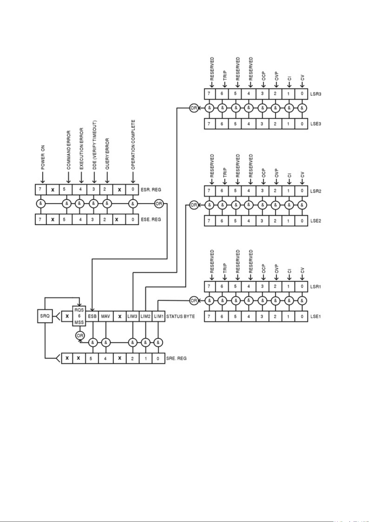
Status Model
Page 33
Page 35

14 Remote Commands (MX100TP only)
14.1 General
14.1.1 Remote and Local Operation
At power-on the instrument will be in the local state, with normal keyboard operation possible.
All remote interfaces are active and listening for a remote command. When any command is
received from any interface the instrument will enter the remote state. In this state the keyboard
is locked out, the display s witc hes to the home screen, with REM displ ay ed in the upper right
corner. The instrum ent may be returned to the local state by pressi ng the LOCAL key; however
the remote state will be immediately re-entered if the inst rument is addressed again or receives
another command from any interface. It is the responsibility of the user to avoid any conflict if
parameters are changed f r om the front panel while in the local state.
14.1.2 Remote Command Handling
Each remote control int er face has a separate input queue which is filled, under interrupt, in a
manner transparent to all other instrument operations. The RS232 interface implements flow
control by sending XOFF when the queue contains approximately 200 characters, and then
XON when about 100 free spaces bec ome available. All the other inter faces have standard
automatic flow control mechanisms built int o their physical layer communication protocol.
Commands are taken from the input queues by the parser as available. Commands and queries
from each queue are executed in order , but the order of execution of commands from different
interfaces is not defined and should not be relied upon. It is strongly recommended that use
should be made of the interface locking facilities described above. The parser will not st art a
new command until any previous c om mand or query is complete. Res pons es are sent to the
interface which issued the query. There is no internal output queue, so on the GPIB interfac e
the response formatt er will wait, indefinitely if neces sary, until the complete response message
has been read by the controller, before the parser is allowed t o s tart the next command in the
input queue. On all other interfaces the response m es s age i s immediately sent into buffers i n
the physical layer.
14.1.3 Remote Command Formats
Commands are sent as <PROGRAM MESSAGES> by the controller, eac h c onsisting of zero or more
PROGRAM MESSAGE UNIT> elements, separated (if ther e is more than one such element) by
<
PROGRAM MESSAGE UNIT SEPARATOR> elements, and finally a <PROGRAM MESSAGE TERMINATOR>.
<
The <
PROGRAM MESSAGE UNIT SEPARATOR> is the semi-colon character ';' (3BH).
PROGRAM MESSAGE TERMINATOR>, which separates or terminates <PROGRAM MESSAGES>, is
The <
the new line character (0AH), but in the case of the GPIB interface the hardware END message
may also be used, either with the last character of the message or with the new line. In the case
of the LAN interface, com mands may not be split across TCP/IP packet boundaries.
PROGRAM MESSAGE UNIT> is any of the commands in the remote commands list, which must
A <
be sent in full as specified. A command must be separated from any p arameters by <
SPACE
character 0AH). No <
any other additional <
treated as <
> (which is defined as the charac ter codes 00H to 20H inclusive, excluding the new line
WHITE SPACE> is permitted within any command identifier or par ameter, but
WHITE SPACE> is ignored. Note that the Backspace character (07H) is
WHITE SPACE>, so it cannot be used to delete incorrect character s , and will not hide
the error.
The high bit of all character s is ignored and all commands are c ase insensitive. Commands that
require a numeric a parameter accept the free form <
as Character Program Data <
CPD> as specified.
NRF> format; text parameters must be sent
WHITE
Page 34
Page 36

<
NRF> numbers must be in basic units, may have a decimal point and frac tional part, and can
include an exponent part if helpful. They are rounded to the precis ion supported by the
instrument.
14.1.4 Command Timing
There are no dependent parameters, coupled parameter s , overlapping commands, expression
program data elements or compound command program headers. .
All commands are separate and sequential, and are executed when parsed and immediately
considered complete. To provide useful functionality, the Operation Complet e bit (bit 0) in the
Standard Event Status Regis ter is only ever set by the *OPC command. Either the *OPC
command or the *OPC? query can be used for device synchronisation due t o the sequential
nature of remote operations.
14.1.5 Response Formats
Responses from the inst r ument to the controller are sent as <RESPONSE MESSAGES>, which
consist of one <
which is the carriage return c har acter (0DH) followed by the new line c haracter (0AH) with, in
the case of GPIB only, the
below.
RESPONSE MESSAGE UNIT> followed by a <RESPONSE MESSAGE TERMINATOR>,
END message NL^END. This is shown as <RMT> in the descriptions
Each query produces a specific <
RESPONSE MESSAGE> which is described in the entry f or the
query command in the rem ote commands list below. Most responses consist of a keyword
followed by either text or a number in one of the following f ormats:
NR1> An integer without a decimal point or a unit.
<
NR2> A fixed point number with a fractional part but no expone nt part.
<
NR3> A floating point number with both a fractional part and an exponent part.
<
CRD> Character Response Data, consisting of the text characters listed.
<
<
N> The number of the output or st atus register to which the command relates.
14.2 Command List
This section lists all the commands and queries implemented in this instrument. All numeric
parameters are shown as <
Command parameters (unlike responses) are not followed by a units indication.
14.2.1 Instrument Function Commands
V<N> <NRF> Set output <N> to <NRF> Volts.
N>V <NRF> Set output <N> to <NRF> Volts with verify.
V<
N> <NRF> Set output <N> over voltage protection trip point to <NRF> Volts.
OVP<
N> <CPD> Enables or disables the over voltage protection trip point where <CPD>
OVP<
NRF> and may be sent as <NR1>, <NR2> or <NR3> as described above.
can be ON or OFF.
N> <NRF> Set output <N> current limit to <NRF> Amps.
I<
N> <NRF> Set output <N> over current protection trip point to <NRF> Amps.
OCP<
N> <CPD> Enables or disables the over current protection trip point where <CPD>
OCP<
can be ON or OFF.
DAMPING<
N>? Return the set voltage of output <N>.
V<
N> <CPD> Set the current meter measurement averaging of output <N> to <CPD>,
where <
Response is V<
CPD> can be ON, OFF, LOW, MED or HIGH.
N> <NR2><RMT> where <NR2> is in Volts.
I<N>? Return the set current limit of output <N>.
Response is I<
N> <NR2><RMT> where <NR2> is in Amps.
Page 35
Page 37

OVP<N>? Return the voltage trip setting of output <N>.
Output3: 1= 35V/3A, 2 = 70V/ 1.5A, 3 = 70V/3A.
Response is VP<
N> <NR2><RMT> where <NR2> is in Volts.
Note: If over voltage protection has been disabled the response is
VP<
N> <CRD><RMT> where <CRD> is OFF.
OCP<N>? Return the current trip setting of out put<N>.
Response is CP<
N> <NR2><RMT> where <NR2> is in Amps.
Note: If over current protection has been disabled the response is
N> <CRD><RMT> where <CRD> is OFF.
CP<
N>O? Return the output readback voltage of output <N>
V<
Response is <
N>O? Return the output readback cur rent of output <N>
I<
Response is <
NR2>V<RMT> where <NR2> is in Volts.
NR2>A<RMT> where <NR2> is in Amps.
DELTAV<
DELTAI<
DELTAV<
DELTAI<
INCV<
INCV<
DECV<
DECV<
INCI<
DECI<
N> <NRF> Set the output voltage step size of output <N> to <NRF> Volts.
N> <NRF> Set the output current step size of output <N> to <NRF> Amps.
N>? Return the output voltage step size of output <N>
Response is DELTAV<
N>? Return the output current step size of output <N>
Response is DELTAI<
N> Increment the output<N> voltage by step size.
N>V Increment the output<N> voltage by step size, with verify.
N> Decrement the output<N> voltage by step size.
N>V Decrement output<N> voltage b y st ep size, with verify.
N> Increment the output<N> current limit by step size.
N> Decrement the output<N> current limit by step size.
N> <NR2><RMT>, where <NR2> is in Volts.
N> <NR2><RMT>, where <NR2> is in Amps.
OP<N> <NRF> Set output<N> on/off where <NRF> has t he following meaning:
0=OFF, 1=ON.
N>? Returns output<N> on/off status.
OP<
NR1><RMT> where 1 = ON, 0 = OFF.
OPALL <
The response is <
NRF> By default simultaneously sets all outputs on/ off where <NRF> has
the following meaning: 0=A LL OFF, 1=ALL ON. However this
behaviour can be changed to turn the outputs on or off in a timed
sequence or to omit an output entirely. See section 9.4 for an
explanation.
VRANGE<
N> <NRF>
Set output<
following meaning:
Output1: 1= 16V/6A, 2 = 35V/3A.
Output2: 1= 35V/3A, 2 = 16V/6A, 3 = 35V/6A.
VRANGE<N>? Returns the voltage range for output<N>. The response is
NR1><RMT> where <NR1> has the following meaning:
<
Output1: 1= 16V/6A, 2 = 35V/3A.
Output2: 1= 35V/3A, 2 = 16V/6A, 3 = 35V/6A.
Output3: 1= 35V/3A, 2 = 70V/1.5A, 3 = 70V/3A.
N> voltage range to <NRF> where <NRF> has the
Page 36
Page 38

CONFIG <
*IDN?
Returns the instrument identification.
*RST
Resets the functional par ameters of the instrument to t he default settings as
*SAV <
>
Save the settings for all three outputs simultaneously to the store specified by
*RCL <
>
Recall the settings for all three outputs simultaneously from the store specified
NRF> Sets the voltage tracking mode of the unit to <NRF> where <NRF>
has the following meani ng:
0 = None.
1 = Mode1.
2 = Mode2.
3 = Mode3.
These modes are as defi ned within the Setting Voltage Track ing
section of this manual – see section 9.1.
CONFIG? Returns t he vo ltage tracking mode of the unit. The response is
NR1><RMT>, where <NR1> has the following meaning:
<
0 = None.
1 = Mode1.
2 = Mode2.
3 = Mode3.
These modes are as defi ned within the Setting Voltage Tracking
section of this manual – see section 9.1.
ONDELAY<
OFFDELAY<
ONACTION<
N> <NRF> Set output<N> Multi-On dela y where <NRF> is in milliseconds
N> <NRF> Set output<N> Multi-Off delay where <NRF> is in milliseconds
N> <CPD> Set output<N> Multi-On action where <CPD> can be QUICK, NEVER
or DELAY.
OFFACTION<
N> <CPD> Set output<N> Multi-Off action where <CPD> can be QUICK, NEVER
or DELAY.
N> <NRF> Save the current settings of output<N> to the store specified by
SAV<
NRF> where <NRF> can be 0-49.
<
N> <NRF> Recall the settings for output<N> from the store specif ied by <NRF>
RCL<
where <
NRF> can be 0-49.
14.2.2 Common Commands
The response is in the form < NAME>, <model>, <serial>, <version><RMT>
where <NAME> is the manuf ac turer's name, <model> is the instrument
type, <serial> is the inte r face serial number and <version> is the revision
level of the firm ware installed.
listed in the Factory Defaul t Settings, see section 18.
Does not affect the contents of the Save and Recall stores.
Does not affect any remote inter face settings.
NRF
<NRF> where <NRF> can be 0-49. This includes output On/Off state, current
meter averaging state, and the Multi-On/Multi-Off sett ings.
NRF
by <NRF> where <NRF> can be 0-49.This includes output On/O ff state, current
meter averaging state, and the Multi-On/Multi-Off sett ings.
Page 37
Page 39

*OPC
Sets the Operation Compl ete bit (bit 0) in the Standard Event Status
Register. This will happen immediately the command is executed because
*OPC?
Query Operation Complet e s tatus.
*TST?
The product has no self-test capability and the response is always 0<
>.
*TRG
The product has no trigger capability. The command is i gnor ed in this
*CLS
Clear Status. Clears all s tatus indications, including the Status Byte.
EER?
Query and clear Execution E r ror Register. The response format is
QER?
Query and clear Query Error R egis ter. The response format is
*STB?
Report the value of the Status Byte. The response is: <NR1><
>.
*SRE <
>
Sets the Service Request Enable Register to <
>
*SRE?
Report the value in the Servic e R equest Enable Register.
*PRE <
>
Set the Parallel Poll Enable Register to the value <
>.
*PRE?
Report the value in the Parallel Poll Enable Register.
*IST?
Returns the state of the ist local message as defined by IEEE Std. 488.2.
of the sequential nature of all operations.
The response is always 1<RMT> and is available immediately the command
is executed because all com mands are sequential.
*WAI Wait for Operation Complete true.
This command does nothing because all operations are sequent i al.
RMT
instrument.
14.2.3 Status Commands
Does not clear any Enable Registers.
LSR<N>? Query and clear the Limit S tatus Register<N>. The response format is
NR1><RMT>. See Status Reporting sec tion for details of the response.
<
N> <NRF> Set the Limit Status Enable Register<N> to <NRF>
LSE<
N>? Retur ns the value in the value in the Lim it S tatus Enable Register<N>.
LSE<
The response fo r mat is<
NR1><RMT>.
<NR1><RMT>.
<NR1><RMT>.
Because there is no output queue, MAV c an only be read by a GPIB serial
poll, not by this query, as any pre vious message must have already be en
sent.
NRF
NRF
The response is <NR1><RMT>.
NRF
NRF
The response is <NR1><RMT>.
The response is 0<RMT> if the local message is false, or 1<RMT> if true.
RMT
Page 38
Page 40

14.2.4 Interface Management Commands
LOCAL
Go to local. Any subsequent com mand will restore the remote state.
IFLOCK
Set or Clear the lock requiring the instrument to respond onl y to this
IFLOCK?
Query the status of the inter face lock.
ADDRESS?
Returns the GPIB bus Address. The response is <NR1><
>.
IPADDR?
Returns the present IP address of the LAN interface, provided it is
NETMASK?
Returns the present netmask of the LAN interface, provided it is connected.
NETCONFIG?
Returns the first means by which an IP address will be sought.
NETCONFIG
Specifies the first means by which an IP address will be sought .
IPADDR
Sets the potential static IP address of the LAN interface (as on the
<NRF>
interface, where <NRF> has the meaning: 0 = clear and 1 = set the lock.
It is an Execution Error (number 200) if the request is denied either because
of conflict with a lock on t his or another interface, or the user has dis abled
this interface fr om tak ing c ontrol using the web interface.
The response is: <NR1><RMT> where <NR1> is
= 0 if there is no active lock,
= 1 if this interface instance owns the lock or
= -1 if the lock is unavailable either because it is in use by another interface
or the user has disabled this interface from taking control (vi a the web
interface).
RMT
connected.
If it is not connected, the r es pons e will be the static IP if configured to
always use that static IP, otherwise it will be 0.0.0.0 if waiting for DHCP or
Auto-IP.
The response is nnn.nnn. nnn.nnn<
RMT>, where each nnn is 0 to 255.
The response is nnn.nnn. nnn.nnn<RMT>, where each nnn is 0 to 255.
The response is <CRD><RMT> where <CRD> is DHCP, AUTO or STATIC.
The following commands specify the parameters to be used by the LAN interface. Note: a
power cycle is required after these commands are sent before the new settings are used (or
returned in response to the queries listed above). The inst r ument does not attempt to check the
validity of the IP address or netmask in any way other than checking that each part fits in 8 bits.
The rear panel LAN RESET switch will override these commands and restore the defaults as
described earlier.
<CPD>
<QUAD>
<CPD> must be one of DHCP, AUTO or STATIC.
webpage).
The parameter must be str ictly a dotted quad for the IP address , with each
NR1> in the range 0 to 255, (e.g. 192.168.1.101).
NETMASK
<QUAD>
address part an <
Sets the netmask to accompany the static IP address of the LA N interface.
The parameter must be str ictly a dotted quad for the netm as k, with eac h
part an <
NR1> in the range 0 to 255, (e.g. 255.255.255.0).
Page 39
Page 41

15 Maintenance
The Manufacturers or their agents overseas will provide a repair service for any unit developing a
fault. Where owners wish to undertake their own maintenance work, this should only be done by
skilled personnel in conjunction with the Service Guide, which may be purchased directly from the
Manufacturers or their agents overseas.
15.1 Cleaning
If the instrument requires cleaning use a cloth that is only lightly dampened with water or a mild
detergent.
WARNING! TO AVOID ELECTRIC SHOCK, OR DAMAGE TO THE INS TRUME NT,
NEVER ALLOW WATER TO GET INSIDE THE CASE.
TO AVOID DAMAGE TO THE CASE NEVER CLEAN WITH SOLVENTS.
15.2 Fuse
The correct fuse type is:
10 Amp 250V HBC time-lag (T), 5 x 20mm
Make sure that only fuses of the required rated current and specified type ar e used for replacement.
The use of makeshift fuses and the short-circuiting of fuse-holders is prohibited.
To replace the fuse, first disconnect the instrument from the AC supply. Remove the 2 cover
securing screws at the rear and slide back and lift off the cover. Replace the fuse with one of the
correct type and refit the cover.
Note that the main function of the fuse is to make the instrument safe and limit dam age in the event
of failure of one of the switching devices. If a fuse fails it is therefore ver y likely that the replacement
will also blow, because the supply has developed a fault; in such circumstances the instrument will
need to be returned to the manufacturer for service.
15.3 Calibration
To ensure that the accuracy of the instrument remains within specification the calibration must be
checked (and if necessary adjusted) annually. The procedure is detailed in the Service Guide, which
also lists the calibrated test equipment required.
15.4 Firmware Update
The firmware of the instrument can be updated through the USB port using a PC software utility
available from the manufacturer. This uses a HID (human interface device) USB class driver which
will already be installed on any PC with a USB port. Instructions for the updat e procedur e are
provided with the PC utility and the firmware file.
Page 40
Page 42

16 Technical Specifications
Voltage/Current
O/P1: Switchable 0V to 35V/0.1mA to 3A or 0V to16V/0.1mA to 6A
Output Power:
Up to 315W total output power
Voltage Setting:
Resolution: 1mV O/P1; 10mV O/P2 and O/P3
Current Setting:
Resolution: 0.1mA O/P1; 1mA O/P2 and O/P3
Operating Mode:
Constant voltage or constant current with automatic cross-over.
Output Switch:
Independent electronic switching with ON indication. In addition, Multi-On
Multi-On/Multi-Off
Individually settable delay between pressing of the Multi-On or Multi-Off ke y
Output Terminals:
Universal 4mm safety binding posts on 19mm (0·75”) spacing for Output;
Ripple & Noise
Outputs 1 and 2 loaded at 16V/6A, Output 3 loaded at 35V/3A, CV mode:
Load Regulation:
For any load change, measured at the output terminals, using remote sense:
Line Regulation:
Change in output for a 10% line change:
Transient Response:
<100us to within 50mV of set level for a 5% to 95% load change.
Temp. Coefficient:
Typically <100ppm/°C
General specifications apply for the temperature range 5°C to 40°C. Accuracy specifications apply
for the temperature range 18°C to 28°C after 15 minutes warm-up with no load and calibration at
23°C. Typical specifications are determined by design and are not guaranteed.
OUTPUT SPECIFICATIONS (Each Output)
Ranges:
Action:
O/P2: 0V to 35V/1mA to 3A, 0V to 16V/1mA to 6A
or 0V to 35V/1mA to 6A with O/P3 disabled.
O/P3: 0V to 35V/1mA to 3A, 0V to 70V/1mA to 1.5A
or 0V to 70V/1mA to 3A with O/P2 disabled
Accuracy: O/P1: 0.05% of setting ± 3mV,
O/P2 and O/P3: 0.1% of setting ± 10mV
Accuracy: ± (0·3% + 3mA) to 3A, ± (0·5% + 3mA ) to 6A
CV or CC mode indication in display.
and Multi-Off keys permit the outputs to be switched on/off synchronously.
and the turning on or off of the respective output. Delays settable between
10ms and 20 seconds. Separate delays for On and Off can be set.
Outputs can also be omitted from Multi-On or Multi-Off control.
screwless terminals for Sense.
MX100TP also has duplicate power and sense terminals at rear.
(20MHz bandwidth):
Voltage Programming
Speed MX100TP only:
(Typical figures)
35V 3A
16V 6A
70V 3A
35V 6A
All Outputs typica l ly <0.5mVrms, < 5mV pk-pk; 1mVrms max.
O/P 3 on 70V/3A range: typically <1mVrms, <10mV pk-pk; 1.5mVr ms max.
Constant voltage: <0.01% ± 5mV
Constant current: < 0.01% ±0.5mA
Constant voltage: <0.01% ± 5mV
Constant current: < 0.01% ± 250uA
Maximum time required for output to settle within 1% of its total excursion
(for resistive load). Excludes command processing time.
90% Load No Load 90% Load No Load
Up
Up
Up
Up
10ms
10ms
25ms
10ms
10ms
10ms
12ms
10ms
Down
Down
Down
Down
60ms
10ms
80ms
20ms
550ms
350ms
850ms
550ms
Page 41
Page 43

Output Protection:
Output will withstand an applied forward voltage of up to 50V (O/P1 and
O/P2), or 80V O/P3. Reverse protection by diode clam p for reverse currents
Over-voltage Protection
Outputs 1 and 2: 1V to 40V. Output 3: 1V to 80V. Output trips off for OVP.
Over-temperature
The output will be tripped off if a fault or blocked ventilation causes the
Voltage/Current Meters
5 digit meters for O/P 1; 4 digit meters for O/P 2 and O/P 3.
Voltage
Resolution: O/P1: 1m V; O/P2 and O/P3: 10mV
Current
Resolution: O/P1: 0. 1mA; O/P2 and O/P3: 1mA
Current Meter Averaging
User selectable On/Off per output with High, Medium or Low settings
V x A:
O/P1: 5-digits. Resolution 0.001W to 100W, 0.01W above 100W.
Stores for Individual
50 store positions for each output. Values stored are Range, Voltage,
Stores for All Outputs:
50 store positions operating on all three outputs simultaneously.
Display:
Black on white backlit graphic LCD, 256 x 112 pixels.
Soft Keys:
Six illuminated multi-function keys annotated from the display.
Home Screen:
Simultaneous display of meters and settings for all outputs.
Individual Screens:
Display of meters and extended settings for an individual output (meters
Numeric Setting:
Floating point numeric entry of voltage, current, OVP or OCP.
Spin Wheel Setting:
Voltage, current and other parameters can be adjusted using the spin
Help Text
Multi-page help text is available for system level functions.
Front Panel Locking:
The lock key can be used to disable front panel control (hold to unlock).
up to 3A.
(OVP) Trip:
Over-current Protection
(OCP) Trip:
Resolution 100mV. Response time: typically 500us. Accuracy: ± (2% ±0.5V)
Measure-and-compare over-current protection is implemented in firmware.
Output trips off for OCP. Setting resolution: 10mA. Response time: typically
500ms. Accuracy: ± (0.3% ±2digits)
Protection (OTP) Trip:
internal temperature to rise excessively.
METER SPECIFICATIONS (Each Output)
Accuracy: 0.1% of reading ± 2 digits
Accuracy: 0.3% of reading ± 2 digits
O/P2 and O/P3: 5-digits. Resolution 0.01W. Accuracy: 0.5% of reading ±
3 digits
SETTING MEMORY STORES
Outputs:
Current, OVP and OCP
Values stored are Range, Voltage, Current, OVP, OCP, Ou tp ut On/Off,
Current Meter Averaging, Multi-On/Multi-Off Setup
USER INTERFACE
Multiple font sizes and graphic icons.
Direct access to voltage or current setting for any output.
in larger font). Direct access for all settings for that output.
wheel in quasi-analog fashion. Wheel can be disabled.
Menu Screen System level functions are selected from a scrollable list.
If required locking can alternatively be done using a secure passcode.
Page 42
Page 44

INTERFACES (MX100TP only)
RS232:
Standard 9-pin D-connector. Baud rate 9600.
USB:
Standard USB 2.0 hardware connection.
LAN:
Ethernet 100/10base-T hardware connection. 1.4 LXI Core 2011.
GPIB:
Conforms with IEEE488.1 and IEEE488.2.
Remote Command
Typically 120ms (80ms min, 160ms max) between receiving the
AC Input:
115V – 240V AC ± 10%, 50/60Hz.
Power Consumption:
500VA max.
Operating Range:
+5ºC to +40ºC, 20% to 80% RH.
Storage Range:
−40ºC to + 70ºC.
Environmental:
Indoor use at altitudes up to 2000m, Pollution Degree 2.
Safety & EMC:
Complies with EN61010-1 & EN3126-1.
Size:
210 x 130 x 375mm (WxHxD) half rack width x 3U height.
Weight:
4.9kg
Options:
19-inch rack kit for one or two units.
Full digital remote control facilities are available through the USB, RS232, LAN and GPIB interfaces.
Setting and readback resolutions are the same as for the Output and Met er s pecif ications
respectively.
Processing Time:
GENERAL
command terminator for a step voltage change at the instrument and
the output voltage beginning to change.
Installation Category II.
For details, request the EU Declaration of Conformity for this
instrument via
http://www.aimtti.com/support (serial no. needed).
Page 43
Page 45

17 Default Values
When supplied from t he fac tory the power supply is set as follo ws:
All Outputs
Voltage 1 volt
Current 0.1 amp
Range 35V/3A
OVP 40V (O/P1 and O/P2); 80V (O/P3)
OCP 7A (O/P1 and O/P2); 3.5A (O/P3)
Current meter averaging Off (Level = Medium)
Voltage tracking None
Output On/Off Off
Multi On/Off action All Quick (synchronous on, synchronous off)
System Level Settings
Power-up state S ettings as at power-down, all outputs off
Beep sound Enabled for key errors and t r ips
Disabled for entry into CC mode
Spin wheel action Normal
The default values can be restored from the “Reset to factory Defaults” function – see s ec tion
9.7.
Page 44
Page 46

 Loading...