

Page 1

1908
5½ Digit Dual Measurement Multimeter
Page 2

CONTENTS
1 Product Description ......................................................................................................4
2 Safety .............................................................................................................................5
Symbols ...............................................................................................................................6
3 Installation .....................................................................................................................7
3.1 Mains Operating Voltage ..........................................................................................7
3.2 Mains Lead ...............................................................................................................8
3.3 Mounting ...................................................................................................................8
3.4 Handle/stand ............................................................................................................8
4 Getting Started ..............................................................................................................9
4.1 Using this Manual .....................................................................................................9
4.2 Installation and Safety ..............................................................................................9
4.3 AC Power and Battery Operation .............................................................................9
4.4 Switching On and Off ................................................................................................9
4.4.1 On/Off operation with AC Power .............................................................................9
4.4.2 On/Off operation without AC Power ......................................................................10
4.4.3 Power-up Settings.................................................................................................10
5 Measurement Connections ........................................................................................ 10
5.1 Input Sockets .......................................................................................................... 10
5.1.1 Multimet er Test Leads ..........................................................................................11
5.2 Rear Panel Connections ......................................................................................... 11
5.2.1 Trigger In/Out ........................................................................................................11
5.2.2 Digital Interfaces ...................................................................................................11
5.2.3 AC Inlet .................................................................................................................11
5.2.4 Protective Earth Terminal .....................................................................................11
6 Making Basic Measurements ..................................................................................... 12
6.1 Scale Length........................................................................................................... 12
6.2 Measurement Parameter Selection ........................................................................ 12
6.3 Measurement Range Select ion .............................................................................. 12
6.4 Making Voltage Measurements .............................................................................. 13
6.5 Making Current Measurements .............................................................................. 13
6.6 Making Resistance Measurements ......................................................................... 13
6.6.1 Two Wire Measurements ......................................................................................13
6.6.2 Four Wire Measurements .....................................................................................14
6.7 Making Continuity and Diode Checks ..................................................................... 14
6.7.1 Continuity Measurem ent .......................................................................................14
6.7.2 Diode Checks .......................................................................................................14
6.8 Making Frequency Measurements ......................................................................... 14
6.9 Making Capacitance Measurements ...................................................................... 15
6.10 Over Voltage Protection ...................................................................................... 15
6.11 Measurement Hold .............................................................................................. 15
6.12 Measurement Null ............................................................................................... 15
6.13 The Cancel Key ................................................................................................... 15
7 Additional Parameters and Functions ....................................................................... 16
7.1 Combined AC + DC Measurements ....................................................................... 16
7.2 Decibel Measurement ( dB) ..................................................................................... 16
7.3 Removing Test Lead Resistance (Ω Null) .............................................................. 16
Page 1
Page 3

7.4 Temperature Measurement (oC/oF) ........................................................................ 17
7.5 Touch and Hold (T Hold) ........................................................................................ 17
7.6 Measurement Speed and Measurement Filter........................................................ 17
7.7 Zero Re-Calibration ................................................................................................ 17
8 Dual Measurement Mode ............................................................................................ 18
8.1 Dual Measurement Combinations .......................................................................... 18
8.2 Making Voltage and Current Dual Measurements .................................................. 19
8.3 Measurement Update Ti mes .................................................................................. 19
9 Triggered Operation .................................................................................................... 20
9.1 Trigger In Signal ..................................................................................................... 20
9.2 Trigger Out Signal (Measurement Complete) ......................................................... 20
10 Advanced and Programmable Functions .............................................................. 21
10.1 Selecting or Cancelling a Function ...................................................................... 21
10.2 Limits ................................................................................................................... 21
10.3 Ax + b .................................................................................................................. 21
10.4 Min-Max .............................................................................................................. 22
10.5 Delta % ................................................................................................................ 22
10.6 Watts ................................................................................................................... 23
10.7 VA ....................................................................................................................... 23
11 Data Logging ............................................................................................................ 23
11.1 Setting-up the Logger .......................................................................................... 23
11.2 Running the Logger ............................................................................................. 24
11.3 Starting and Stopping the Logger ........................................................................ 24
11.4 Recalling Logger Readings ................................................................................. 24
11.5 Clearing Logger Readings ................................................................................... 24
12 The Utilities Menu .................................................................................................... 25
12.1 Beep Sound {BEEp} ............................................................................................ 25
12.2 Measurement Speed {SPEEd} ............................................................................ 25
12.3 Measurement Filter {FiLt} .................................................................................... 25
12.4 External Trigger {E-tr} .......................................................................................... 25
12.5 Battery Condition {bAtt} ....................................................................................... 25
12.6 dB Reference Impedance {db-rEF} ..................................................................... 25
12.7 Temperature Probe Setup {rtd} ........................................................................... 26
12.8 Set Factory Defaults {rESEt} ............................................................................... 26
12.9 Switch Off on AC Power disconnection {AC OFF}............................................... 26
12.10 Measurement Update S ym bo l {StAr} ................................................................... 26
12.11 GPIB Address {Addr} ........................................................................................... 26
13 Maintenance ............................................................................................................. 27
13.1 Calibration ........................................................................................................... 27
13.1.1 Zero Calibration ....................................................................................................27
13.1.2 Routine Calibration ...............................................................................................27
13.2 Hard Reset .......................................................................................................... 27
13.3 Fuse Replacement .............................................................................................. 27
13.3.1 Current Range Fuses ............................................................................................27
13.3.2 Internal AC power fuse .........................................................................................28
13.4 Cleaning .............................................................................................................. 28
13.5 Firmware Updates ............................................................................................... 28
Page 2
Page 4

14 Remote Operation .................................................................................................... 29
14.1 GPIB Interface ..................................................................................................... 29
14.2 RS232 Interface .................................................................................................. 29
14.3 USB Interface and Device Driver Installation ...................................................... 30
14.4 LAN Interface ...................................................................................................... 30
14.4.1 LAN IP Address and Hostname ............................................................................31
14.4.2 mDNS and DNS-SD Support ................................................................................31
14.4.3 ICMP Ping Server .................................................................................................31
14.4.4 Web Server and Configuration P as sword Protection ............................................31
14.4.5 LAN Identify ..........................................................................................................31
14.4.6 LXI Discovery Tool ................................................................................................32
14.4.7 VXI-11 Discovery Protocol ....................................................................................32
14.4.8 VISA Resource Name ...........................................................................................32
14.4.9 XML Identification Docu ment URL ........................................................................32
14.4.10 TCP Sockets .....................................................................................................32
15 Status Reporting ...................................................................................................... 32
15.1 Input Trip Registers (ITR & ITE). ......................................................................... 33
15.1.1 Input Trip Register (ITR) .......................................................................................33
15.2 Standard Event Status Registers (ESR and ESE) .............................................. 33
15.3 Execution Error Register (EER)........................................................................... 34
15.4 Status Byte Register (STB) and GPIB Service Request Enable Register (SRE) 34
15.5 GPIB Parallel Poll (PRE) ..................................................................................... 35
15.6 Query Error Register - GPIB IEEE Std. 488.2 Error Handling ............................. 35
15.7 Power on Settings ............................................................................................... 35
15.8 1908 Status Model .............................................................................................. 36
15.9 Register Summary ............................................................................................... 36
16 Remote Commands ................................................................................................. 37
16.1 General ............................................................................................................... 37
16.1.1 Remote and Local Operation ................................................................................37
16.1.2 Remote Command Handling .................................................................................37
16.1.3 Remote Command Formats ..................................................................................37
16.1.4 Command Timing..................................................................................................38
16.1.5 Response Formats................................................................................................38
16.2 Command List ..................................................................................................... 39
16.2.1 General Commands ..............................................................................................39
16.2.2 Main Display Commands ......................................................................................40
16.2.3 Dual Measurement Mode Commands...................................................................42
16.2.4 First Level Modifier Commands ............................................................................42
16.2.5 Second Level Modifier Commands .......................................................................43
16.2.6 Data Logging Commands .....................................................................................44
16.2.7 Common Commands ............................................................................................45
16.2.8 Status Commands ................................................................................................45
16.2.9 Interface Management Commands .......................................................................46
17 Default Settings........................................................................................................ 47
18 Graphical Interface PC software ............................................................................. 48
19 Specifications .......................................................................................................... 49
Note: This manual is 48581-1470 Issue 3
Page 3
Page 5

1 Product Description
This precision bench-top/portable multimeter has dual measurement capability and a dual
display which can show either two independent measur ements, a measurement together with
its range value, or a measurement with one of the many programmable functions available.
The key features are:
• Operation from AC line or built-in rechargeable batteries.
• 0.02% basic accuracy, 120,000 counts.
• Manual or Auto-ranging.
• DC and AC Volts, DC and AC current, Resistance, Capacitance, Frequency, and
Temperature measurement; Continuity and Diode checks.
• True RMS AC and AC+DC measurement.
• Two or Four wire selectable ohms measurement.
• Display nulling and Ohms null.
• Selectable measurement speed.
• Touch hold mode - holds onto a stable reading until updated.
• 500 point data logger with timer.
• Temperature measurement for PT100 or PT1000 sensors.
• Measurement post-processing to give:
dB and power measurement with settable reference impedances
percentage deviation from a user-entered reference
linear scaling with offset
limits comparison for go/no go testing
automatic storage of minimum and maximum readings.
• Remote control via USB interface (1908)
• Remote control via USB, RS232, GPIB and LAN (LXI) interfaces (1908P)
• External input/output remote triggering.
• 1908-PC Link software providing:
Remote control of main functions
Logging function with graphical & tabular displays
Logged data can be exported to a CSV file
• Closed case calibration.
• Fully compliant with EN61010-1, EN61010-2-030 & EN61010-2-033 Safety, and
EN61326-1 EMC standards.
Page 4
Page 6

2 Safety
This multimeter has been designed to meet the requirements of EN61010-1, EN61010-2-030 &
EN61010-2-033 (relevant parts of the ‘Safety Requirements for Electrical Equipment for
Measurement, Control and Laboratory Use’ standards). It can be operated from its built-in
rechargeable battery or from a standard AC mains supply (Overvoltage Category II). When
connected to AC mains, it is a Safety Class I instrument.
WARNING! THIS INSTRUMENT MUST BE EARTHED
Any interruption of the mains earth conductor inside or outside the instrument will make the
instrument dangerous. Intentional interruption is prohibited. The protective action must not be
negated by the use of an extension cord without a protective conductor.
When operated from the internal battery, without an AC mains connection, the multimeter should be
earthed by connecting the rear panel Chassis Earth terminal to an external protective earth system.
Without this connection, ‘leakage’ current from any accessible part may exceed the Normal (s afe)
limit of 0.5mArms under some extreme measurement conditions, e.g. high voltage, high frequency,
AC volts measurement. Measurements to 300VACrms, 50/60Hz, for example, would not require this
protective earth connection.
The test leads supplied with this instrument meet the requirements of EN61010-031 and are rated to
1000V Cat III; use only these test leads with the meter or a set of equivalent performance.
This instrument has been tested in accordance with EN61010-1 and has been supplied in a safe
condition. This instruction manual contains some information and warnings which have to be
followed by the user to ensure safe operation and to retain the instrument in a safe condition.
This instrument has been designed for indoor use in a Pollution Degree 2 environment (only dry
non-conductive pollution occurs except that occasionally a temporary conductivity caused by
condensation is expected) in the temperature range 5°C to 40°C, 20% - 80% RH (non-condensing).
It may occasionally be subjected to temperatures between +5° and −10°C without degradation of its
safety.
It has been designed for measurement use to 1000VDC/750VACrms in circuits isolated from AC
mains power (derived secondary circuits within an equipment) with occasional transient overvoltages up to 1500Vpeak. It can also be used for CAT II (Measurement Category II) use to
600VDC/ACrms, and CAT III use to 300V DC/ACrms. CAT II is local domestic supply level, e.g.
portable equipment and appliances; CAT III is mains distribution parts of a building.
For this equipment 4000V is the maximum peak transient overvoltage that can be tolerated by any
terminal with respect to earth ground without impairing safety.
Use of this instrument in a manner not specified by these instructions may impair the safety
protection provided. Do not operate the instrument outside its rated supply voltages or
environmental range. In particular excessive moisture may impair safety.
When the instrument is connected to its supply or its inputs are connected to live voltages, terminals
may be live and opening the covers or removal of parts (except those to which access can be
gained by hand) is likely to expose live parts. The apparatus shall be disconnected from all voltage
sources before it is opened for any adjustment, replacement, maintenance or repair, including the
replacement of the current range protection fuses. Any adjustment, maintenance and repair of the
opened instrument under voltage shall be avoided as far as possible and, if inevitable, shall be
carried out only by a skilled person who is aware of the hazard involved.
If the instrument is clearly defective, has been subject to mechanical damage, excessive moisture or
chemical corrosion the safety protection may be impaired and the apparatus should be withdrawn
from use and returned for checking and repair. Make sure that only fuses with the required rated
current and of the specified type are used for replacement. The use of makeshift fuses and the
short-circuiting of fuse holders is prohibited.
Do not wet the instrument when cleaning it and in particular use only a sof t dry cloth to clean the
display window.
Page 5
Page 7

Symbols
CAUTION - refer to accompanyi ng
Measurement Category I I. Inputs may be
alternating current
Measurement Category I II. Inputs may be
The following symbols are used on the instrument and in this manual:
WARNING - risk of electric shock.
documentation; incorrect operation may
damage the meter.
CAT II
connected to AC mains power under
Category II overvoltage conditions
CAT III
connected to AC mains power under
Category III overvoltag e conditions
mains earth (ground)
Protective Earth terminal
direct current
Standby supply. Instrument is
not disconnected fr om AC
mains power when switch is off.
Page 6
Page 8

3 Installation
3.1 Mains Operating Voltage
Check that the instrument operating voltage marked on the r ear panel is suitable for the loc al
supply. Should it be necessary to change the operating voltage, proceed as follows:
1. Warning! Disconnect the instrument from all voltage sources before beginning this
procedure.
2. Pull out both sides of the handle at the case pivot points, to fr ee the position locking
pegs, and rotate the handle from the stowed position to the position shown below. Then
pull the sides of the handle outwards fully, one at a time, to remove the handle
completely.
3. Remove the two screws on the rear panel that retain the top cover and slide the top
cover towards the rear, with the soft bezel still in place, until it can be lif ted clear.
Note: To avoid contaminating or damaging the PCB assembly, take care not to touch
any components other than the two shorting connectors described in the next step.
4. Remove the shorting connector in position PJ4 on the PCB beside the mains
transformer (TX1) and replace it with the alternative shorting connector from the
‘parking’ position PJ8; align pin1 of the connector with the pin 1 corner marker of the
header. ‘Park’ the unused connector on PJ8, see the diagrams below.
For 230V operation PJ4 should be fitted with the connector which has a single red wire
between its centre pins (pins 2 & 3).
For 115V operation PJ4 should be fitted with the connector which has a blue wire
between pins 1 & 3, and a brown wire between pins 2 & 4.
Note that the value of fuse FS3 (500mA) is the same for both AC voltage settings, see
Maintenance, section 13.
5. Reassemble in the reverse order.
6. To comply with safety standard requirements the operating voltage marked on t he rear
panel must be changed to clearly show the new voltage setting.
Page 7
Page 9
3.2 Mains Lead
For AC mains operation, connect the instrument to the AC supply using the mains lead provided.
Should a power plug be required for a different power outlet socket, a suitably rated and approved
mains lead set should be used which is fitted with the required wall plug and an IEC60320 C13
connector for the instrument end. To determine the minimum current rating of the lead-set for the
intended AC supply, refer to the power rating information on the equipment or in the Specification.
WARNING! THIS INSTRUMENT MUST BE EARTHED.
Any interruption of the power earth conductor inside or outside the instrument will make the
instrument dangerous. Intentional interruption is prohibited.
3.3 Mounting
This instrument is suitable both for bench use and rack mounting. It is delivered with soft protective
front and rear bezels which have integral moulded feet; this is the most suitable configuration for
bench use.
For rack mounting the protective bezels and handle/stand can be removed such that the instrument
can be fitted beside any other standard 2U half-rack instrument in a 19” rack. A suitable 2U 19”
rack kit is available from the Manufacturers or their overseas agents; full details of how to remove
the handle and bezels are included with the kit.
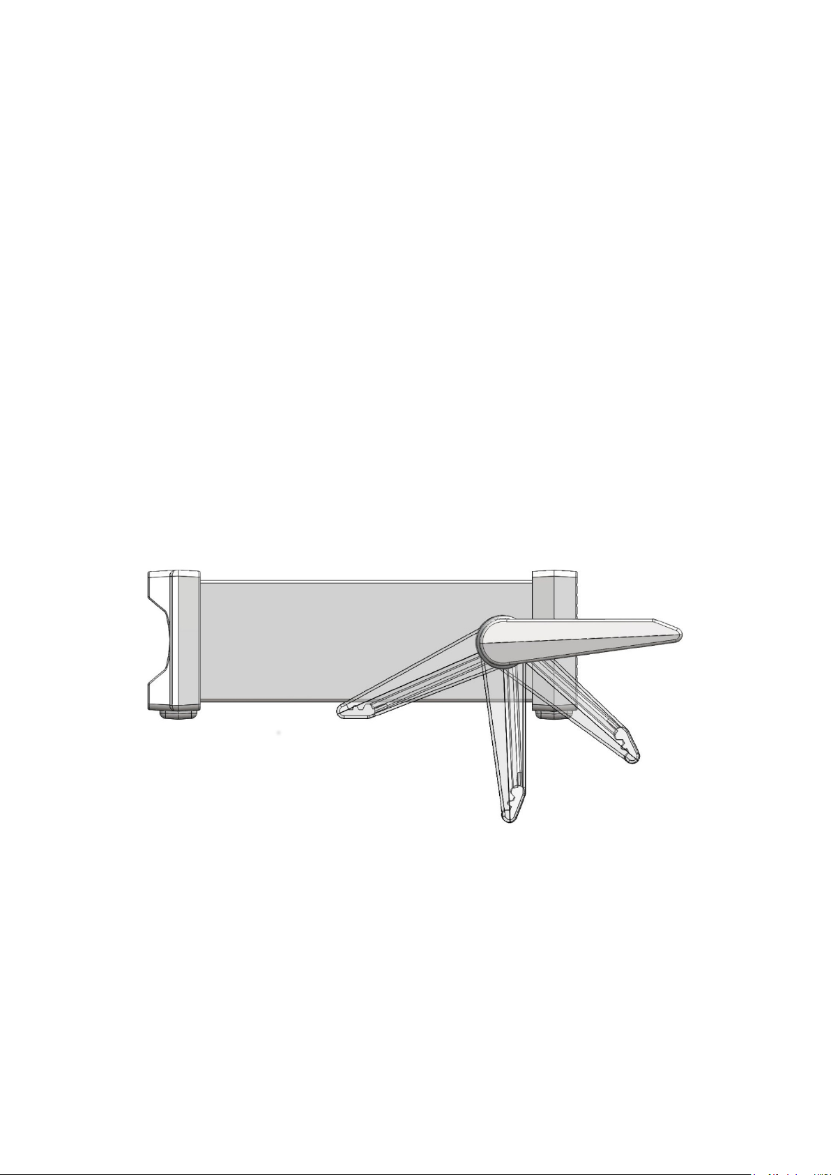
3.4 Handle/stand
The instrument is fitted with a 4-position handle/stand. Pull out both sides of the handle at the case
pivot points, to free the position locking pegs, and rotate the handle from the stowed pos it ion to the
required stand or handle position. Release the sides of the handle to lock it in the new position.
Page 8
Page 10

4 Getting Started
4.1 Using this Manual
In this manual front panel k eys are shown in bold square brackets , e.g. [Vdc], [Function].
Sockets are shown in bold capitals, e.g. INPUT HI. LCD display dat a is show in bold curly
brackets, e.g. {SPEEd}, {AUTO}.
The manual is available in pr i nted form and as an electronic document in PDF format. The
manual includes cross r eferences which are underlined within the text. These are hyperlinks
within the PDF document . The Table of Contents is also fully h yperlinked.
Hyperlinks enable the u s er to jump rapidly to the section referred to and then jump back to
continue reading the original section. (N.B. f or hyper l ink navigation within Acrobat Reader,
enable “show all page navigat ion tools” or use the keyboard shortcuts Alt+Left_Arrow and
Alt+Right_Arrow).
4.2 Installation and Safety
Before first use, all user s should read the Safety Information in section 2 .
Before connecting AC power, c hec k that the instrument operating voltage marked on the rear
panel is suitable for t he local supply. Should a change be required, read section 3.1
Connect the instrum ent to the AC supply using the mains lead provided. Should a power plug
be required for a different power outlet socket, refer to section 3.2
.
4.3 AC Power and Battery Operation
The instrument can be operat ed from AC power or from internal rechargeable batteries which
are recharged as required when AC power is connected. A red LED is illuminated whenever
AC power is connected and a yellow LED is illuminated whilst c harging is taking place.
Battery Life from fully charged is approximately 20 hours with the backlight on, and up to 35
hours with the backlight off. Under battery operation a battery symbol will appear on the display
if the charge level falls belo w about 10%. The approximat e charge level can be checked from
the Utilities menu – see section 12.5.
For the 1908P, operation of the remote interfaces (excludi ng USB) is only possible with AC
power connected.
4.4 Switching On and Off
The instrument behaves differently depending upon whether or not AC power is connected.
4.4.1 On/Off operation with AC Power
If required, AC power can be switched on or off using the POWER switch mounted on the rear
panel. When the AC power is switched off the default setting is for the instrument to turn off. Th i s
ensures appropriate behaviour when used as part of a group of equipment for which AC power is
turned on or off simultaneously.
Note: To fully disconnect from the AC supply unplug the mains cord from the back of the
instrument or switch off at the AC supply outlet; make sure that the means of disconnection is
readily accessible. Disconnect from the AC supply when not in use.
The green front panel button marked [OPERATE] can be used to place the instrument into
Standby if required. Successive presses will alternate between On and Standby.
Alternative AC Power Swi tching Options
The response of the instrument to AC power being connected or disc onnected can be altered if
required. The actions described above are the default conditions, and can be changed fr om the
Utilities menu – see section 12.9
.
Page 9
Page 11
4.4.2 On/Off operation without AC Power
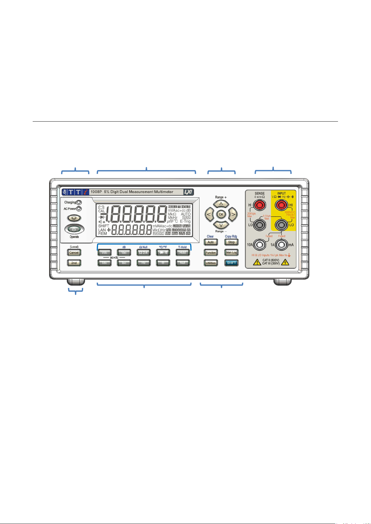
Display
Measurement
Measurement keys
Navigation
Function keys
Power
Function keys
With no AC power connected, operation is from the internal r ec hargeable batteries and the
instrument is turned on or off by successive presses of t he green [OPERATE] button. The rear
panel POWER switch has no funct i on.
4.4.3 Power-up Settings
At power up the display briefly shows the installed software revision; the instrument is then restored
to the same measurement conditions as at power down, including any advanced functions that were
running. However, if the instrument was showing a menu at power down, the menu will be
cancelled when powered up.
5 Measurement Connections
5.1 Input Sockets
keys
The input sockets are 4mm safety sockets on a 19mm pitch designed t o accept 4mm safety
plugs with fixed or retra ctable shrouds. All sockets are rated to 1000Vpeak with res pec t to earth
ground. Safety will be maintained if voltages up to 1000Vpe ak are accidentally applied between
inappropriate terminals in excess of their marked ratings, but restoration of normal operation
may require replacement of protection devices (e.g. cur rent range fuses).
terminals
The input impedance between INPUT HI and INPUT LO is nominally 10MΩ on dc r anges and
1MΩ on ac ranges. The black LO soc k et is considered less positive than the red socket. The
maximum voltage that can be app lied between HI & LO is 1000Vdc, 750Vrms (1000Vpeak).
The sockets are rated to 600V CAT II, 300V CAT III.
The mA/10A current sockets are low impedance; the voltage burden between mA/10A and LO
at full scale is <100mV for the 10mA range and <600mV for the 100mA, 1A and 10A ranges.
The black LO socket is considered less pos itive than the white mA/10A sockets. The mA/1A
socket is protected with a 1.6A 1kV HRC fuse, and the 10A socket with a 10A 1kV fuse; see
Maintenance, section 1 4, for replacement details.
The SENSE HI & LO sockets are only used in 4-wire Ohms and RTD temperature
measurements; refer to those sections for details. When used, the maximum differential
between SENSE LO and INPUT LO should be < 0.5V peak . The SENSE terminals are
protected against accidental connection of up to 200Vpeak between HI & LO.
Page 10
Page 12
5.1.1 Multimeter Test Leads
The test leads supplied meet the requirements of IEC1010-031 and are rated to 1000V Cat
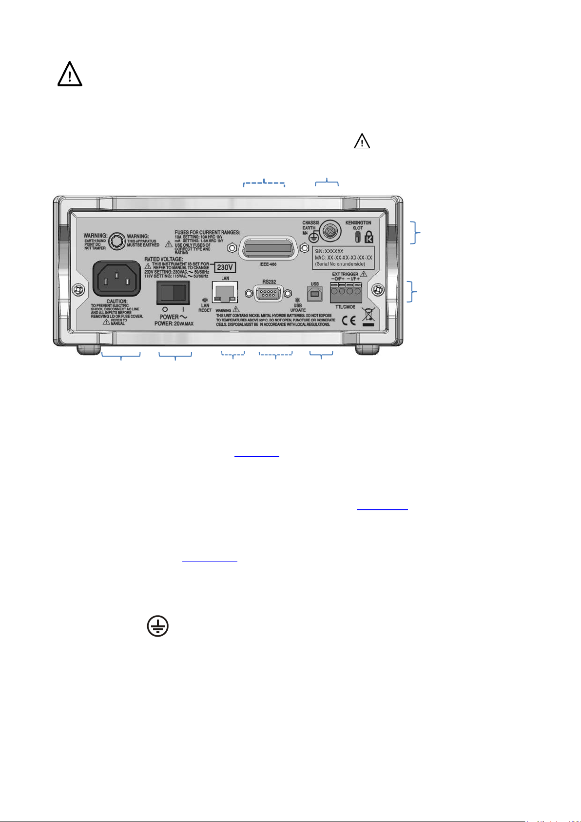
TTL/CMOS
External Trigger
Kensington
USB
RS232
LAN
Power
switch
AC power
Protective
(1908P)
GPIB
III. Use only the test leads pr ovided, or a set of similar performance, to ensure safe
operation. Alternativ e test leads should be rated to at least 1000V, 600V (Cat II) and 10A
current capability.
5.2 Rear Panel Connections
connection
(1908P
only)
Conductor
Terminal
Warning! This instrument must be
earthed. Connect terminal to an external
protective earth system when instrument
is used without an AC mains connection.
Lock
5.2.1 Trigger In/Out
Screw-less connectors are provide d on the rear panel for the connec tion of an external trigger
signal, and a trigger out s ignal . See section 9
for full details.
5.2.2 Digital Interfaces
Depending upon model, r ear panel connectors are provided for USB only (1908) or USB,
RS232, LAN and GPIB (1908P). Refer to Remote Operation, section 14
, for full details.
5.2.3 AC Inlet
The instrument can be connected to AC mains using the power lead supplied or a suitable
alternative, see Installation section 3.2.
When the power lead is connected this lead provides the
necessary protective earth connection to an external protective earth system.
5.2.4 Protective Earth Terminal
For battery only operation, without an AC power lead connected, the M4 threaded chassis
connection marked must be connected to an external protective earth system via a
green/yellow insulated cable, with a cross-section of at least 0.75mm
Without this connection, ‘leakage’ current from any accessible part may exceed 0.5mArms, t he
Normal (safe) limit specified by EN61010-1, under some extreme measurement conditions, e.g. high
voltage, high frequency, AC volts measurement.
. WARNING! THIS INSTRUMENT MUST BE EARTHED.
2
, fitted with a M4 terminal.
Page 11
Page 13
6 Making Basic Measurements
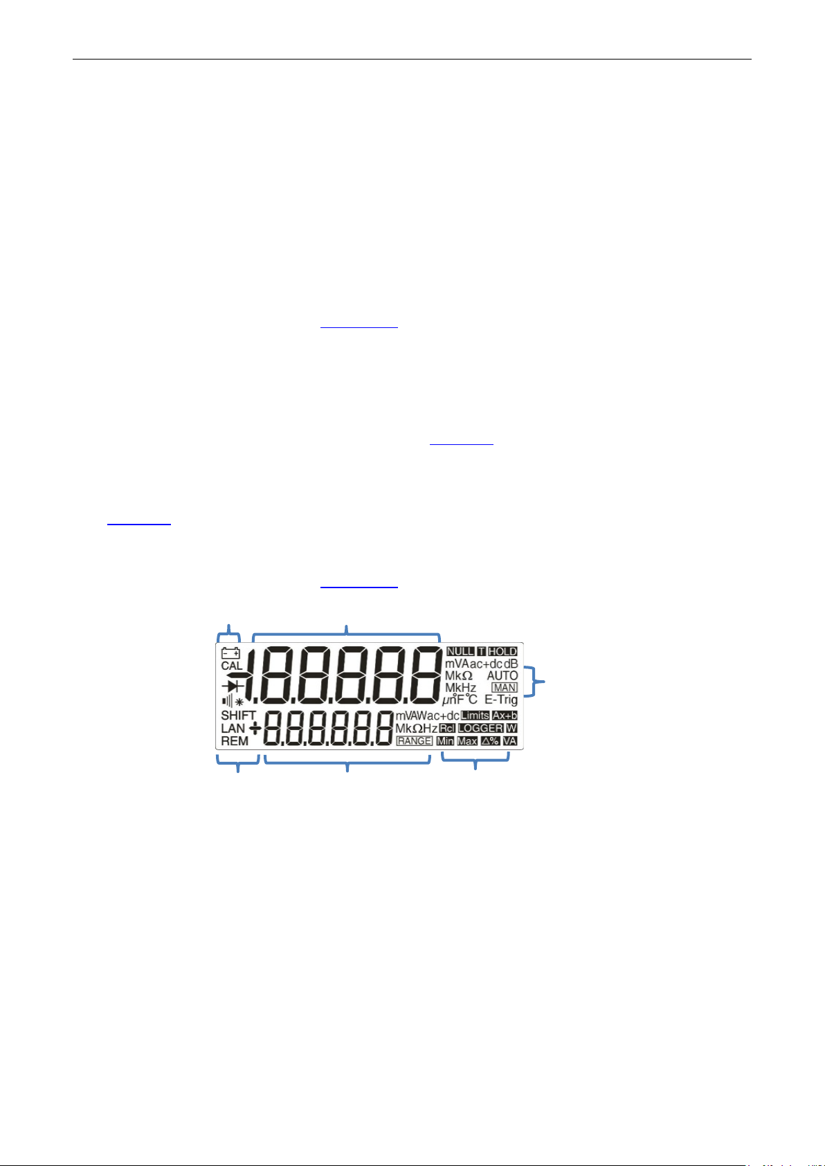
Primary measurement
Range or
Functions
Remote
Status
Range
This section describes how basic measurements are made, i.e. single measurement mode
without post-processing of the results.
6.1 Scale Length
The scale length is ±120,000 f or all measurements except frequency (full scale 12,000) and
capacitance (full scale 1200). {OFL} is displayed when the range maximum is exceeded.
Note, however, that safety considerations limit the maximum voltage and current that can be
measured to below the scale length maximum.
6.2 Measurement Parameter Selection
Refer to the f r ont panel diagram in section 5.1
The two rows of darker grey keys below the display directly select t he measurement
parameters for either the primary or secondary display. When pressed alone the param eter
keys select the measurement parameter for the primary display, cancel any secondar y
functions, and set the range to auto-range.
Pressing [2nd] followed by a parameter key selects the parameter for the secondary display;
this is explained fully in Dual Measurement Mode, section 8
combinations of parameters that can be used.
Additional paramet ers marked in blue above certain keys are selected by first pressing [SHIFT].
Whilst shift is operational a {SHIFT} symbol appears on the left side of the display.
See section 7
for full details.
, which also details the
6.3 Measurement Range Selection
Refer to the front panel diagram in section 5.1, and to the display diagram below.
communications
2nd measurement
When a parameter is first selected, auto-ranging is enabled and a n {AUTO} s ymbol is
displayed. Pressing either of the [ᴧ] / [v] arrow keys (Range+/Range-) cancels auto-ranging
whilst leaving the range set to its existing value. The {MAN} symbol is displayed and further
presses then change the range up wards or downwards. Pressing [OK] returns the ins trument
to auto-ranging operation.
The units appropriate to the function and range (e.g. {mV ac}) ar e s hown to the right of the
display. When the secondary display is not being used to sho w m easurement values, the
selected range is shown there.
Note that the 10A range, which uses a different input socket from mA measurements, can only
be selected manually. Once 10A has been selected, however, this setting will be retained for
current measurem ent unt il i t is returned to mA.
Note that the {AUTO} and {MAN} symbols apply only to the pr imary display.
Mode
Page 12
Page 14

6.4 Making Voltage Measu rements
The maximum voltage that can be applied between INPUT HI and LO is 1000V DC or 750V
The input test leads and AC power lead must be disconnected before opening the fuse
Having selected Vdc or Vac, volt age measurements are made us ing the red INPUT HI socket
and the black INPUT LO socket within the yello w area of the panel. Five measurement ranges
(auto or manual) are available from 100mV to 1000V (dc) or 750V (ac).
The meter will show a minus sign {-} (on dc measurements) when the volt age applied to the
INPUT HI socket is more negative than that applied to the INPUT LO socket.
AC; damage to the instrument may result if this limit is exceeded.
WARNING! The maximum input volt age to ground must not exceed 1000V peak. Safety will be
impaired if thes e ratings are exceeded, see Safety section at the beginning of the manual.
6.5 Making Current Measu rements
Having selected Idc or Iac , current measurements up to 1. 2A (1200.00mA) are made using the
white mA socket and the black INPUT LO socket; cur rent measurements up to 10A are made
using the 10A and LO sockets. The meter will show a minus sign {-} (on dc measurements)
when the polarity of the cur r ent is such that it flows out of the mA or 10A sockets rather than
into it.
Using the mA socket three measurement ranges ( auto or manual) are available f r om 10mA to
1000mA. Measurements up to 10A c an be made using the 10A socket having manually ranged
to 10A with [ᴧ].
The 10mA, 100mA and 1000mA ranges, using the mA socket, are protect ed by a 1.6A (F) HRC
fuse. The 10A range, using the 10A socket, is protected by a 10A (F) HRC fuse. Both fuses are
accessed via a panel on the bas e of the instrument.
access panel.
Note: After measuring high currents (i.e. above half sc ale) using the 1A or 10A ranges, thermal
voltages are generated t hat may create errors when making measurements on the most
sensitive dc voltage, current or Ohms ranges immediat el y afterwards. To ensure that t he
specified accuracy is maintained, allow 10 minutes for the thermal effects to reduce before
making sensitive meas ur ements.
6.6 Making Resistance Measurements
Pressing [Ω 2/4] selects resistance measurement in either 2 wire or 4 wire mode. Successive
presses alternate between the modes as indicated by {2W
secondary display. Six measurement ranges (auto or manual) ar e available from 100Ω to
10MΩ.
6.6.1 Two Wire Measurements
Normal (2 wire) resistanc e measurements are made using the INPUT HI and LO sockets within
the yellow area of the panel. This measurement mode is appropriate for higher r es istance
measurements, and for lower res istance measurement s where high precision is not required.
Ω} or {4WΩ} appearing briefly in the
The effects of test lead resis tance can be removed using Ω Null if required – see section 7.3
Page 13
.
Page 15
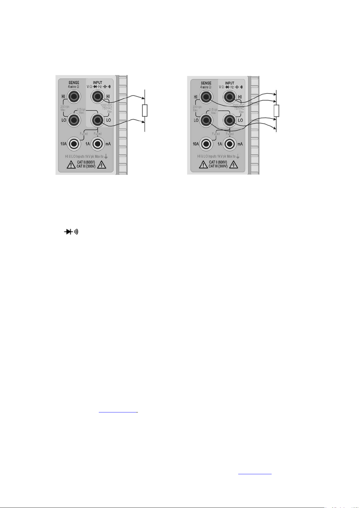
6.6.2 Four Wire Measurements
4 wire measurements are appropr iate for precision measur ement of low resistances where the
effects of the connectin g l eads and contact resistances are significant. 4 wire measurement
uses the HI and LO SENSE sockets in addition to the HI and LO INPUT sockets.
Connections are made as shown below.
Two Wire Measurement Four Wire Measurement
Because no significant current is flowing through the SE NS E connections when utilising 4 wire
measurement, contact resistance does not affect the measurement result.
6.7 Making Continuity and Diode Checks
Pressing [ ] selects either cont inuity measurement or diode test. Successive presses
alternate between the two as indicated by symbols on the left side of the displ ay. Continuity
and diode checks are made using the INPUT HI and LO sockets within the yellow area of the
panel.
6.7.1 Continuity Measurement
Setting continuity causes the 1000Ω range to be selected such that readings be low
approximately 10Ω will sound the continuity buzzer. Readings above the range maximum will
show {OPEn}.
6.7.2 Diode Checks
Setting diode check caus es the 1000mV range to be selected and a current of approximately
1mA to flow out of the INPUT HI socket. W ith the anode of the diode connected to this t erminal
the diode forward voltage will be shown. Reverse diode connecti on will show {OFL}.
6.8 Making Frequency Measurements
Pressing [Hz] selects frequency m eas urement. Measurements are m ade using the INPUT HI
and LO sockets within the yellow area of the panel. Four ranges (100Hz to 100k Hz) are
available, giving resol utions of 10mHz to 10Hz respectively over an operating fr equenc y range
of <10Hz to 120kHz. Reciprocal counting techniques ensure fast reading updates
(4 readings/second) even on the lowest range. This can be increased to 8 readings/second in
fast speed mode see section 12.2
measuring low frequencies in the 100Hz range to ensure accurat e r eadings.
; however the slow speed mode should always be used when
Measurements are m ade using the ac Volts input circuitry which is auto-ranged to provide
suitable sensitivity. At low signal levels use a screened lead an d an adaptor (BNC to 4mm
plugs, 19mm pitch) to preserv e signal quality and avoid spurious r eadings from stray pick-up.
The minimum measurable signal is <30mV rms across the frequency range (100mV range) or
<10% of range maximum for other ac voltage and current ranges.
Frequency can also be meas ur ed in dual measurement mode, see section 8.1
Page 14
.
Page 16

6.9 Making Capacitance Measurements
Pressing [ ] selects capacitance measurement. Measurements are made using the INPUT
HI and LO sockets within the yello w area of the panel. Five ranges ( 10nF to 100µF) are
available with 1200 count full scale giving resolutions of 10pF to 100nF respectively.
Zero calibration at the factory is carried out with no test leads c onnected; ideally, capacitor s to
be measured should be connected directly to the sockets. Test leads, if used, should be kept as
short as possible to minimise stray capacitance but never theless a non-zero reading will
generally be present when the lowest ranges are selected. To eliminate this offset it is
recommended that the meter reading is nulled, once the required range has been selected, with
the test leads in their measurement positions but no capacit or connected.
It is also recommended that battery operation is used when making capacitance
measurements, to m inim i s e reading jitter. Note that, becaus e the capacitor is discharged
between each measurem ent, the reading rate on the 100µF range is slower.
6.10 Over Voltage Protection
When making measurements of Resistance, Capacitance, Temperature, Continuity or Diode
checks an internal protection circuit protects t he current source from source voltages applied to
the INPUT HI and LO sockets. If a voltage of greater than typically 10V is applied to the INPUT
HI and LO sockets the protection circ ui t will be engaged, the buzzer will sound and {trIP} will be
displayed. After completion of the trip event, the measurement mode is set to V dc to show the
over-voltage that is bein g appl ied to the input sockets. BIT 0 of the Input Trip Register (IT R) is
set to 1 (over voltage protec t) see section 15.1
.
6.11 Measurement Hold
Hold operates only on the primary display. Pressing [Hold] causes t he measurement to be
frozen on the display along with a {HOLD} symbol. Provided that the meter is not in dual
measurement mode and not measuring capacitance, t he normal, updated, reading will be
shown in the secondary display.
Hold only operates on the primary display, any measurement being shown on the secondary
display will continue to updat e normally.
Hold is cancelled by pres s i ng [Hold] again, or by changing range or function.
6.12 Measurement Null
Null operates only on the primary display. Pressing [Null] causes the measurement to be
stored and subtracted f rom all future readings. Pressing [Null] locks the meter in the selected
range and shows {NULL} (and {MAN}) symbols. Provided that the meter is not in dual
measurement mode and not measuring capacitance, t he normal, un-nulled, reading will be
shown in the secondary display.
Null is cancel by pressing [Null] again, or by changing range or function.
6.13 The Cancel Key
[Cancel] can be used to return t he meter to a basic measurement mode. It cancels dual
measurement mode, dB, N ull, Hold and T-Hold, and any programmable functions including the
Logger. It does not cancel Ω Null.
Consequently [Cancel] should not be used to cancel a single function, such as Hold, if other
functions need to be maintained.
Page 15
Page 17

7 Additional Parameters and Functions
A number of additional capabilities can be accessed using the measurement parameter keys,
as described below. Further functions also can be selected from the Functions menu key – see
section 10.1
7.1 Combined AC + DC Mea surements
Vdc+Vac or Idc+Iac measurements are made by pressing both keys t ogether. The reading
displayed is the RMS sum √(dc
Both ac and dc measurements are made on the same range: the instrument will auto-range to a
range which gives an in-range reading for both the ac and dc component of the parameter.
Clearresult to be shown as an in-range reading.
2
+ ac2) and ac+dc is shown on the displa y.
Note that this is a special case of Dual Measurement mode (see section 8.3
measurement update rate is slowed accordingly.
) and the
7.2 Decibel Measurement (dB)
dB (deciBel) can be selected only when Vac is already in the main display. Pressing [Shift]
followed by [Vac] shows the dB value of the Vac measurement (referred to the chosen
impedance setting) and dis plays the {dB} symbol. If no secondary f unc tion is selected the
normal reading in volts will be s hown in the secondary displa y.
dBs are shown in a fixed format with 0.1dB resolution, whatever r ange the Vac measurement is
being made on. The value displayed is in dBm and is calculated from the formula:
dB = 10 log10 (1000 x V2/R), where R is the selected reference impedance.
The default reference impedance is 600Ω but a different value can be selected within the
Utilities menu. Press [Utilities], use the Navigator keys to select {rEF} and confirm with [OK].
The existing reference v alue will flash. Alternativ e val ues can be selected using the Navigator
keys and confirmed with [OK].
Available values are 50, 75, 93, 110, 124, 125, 135, 150, 250, 300, 500, 600, 900, 1000, 1200,
and 8000Ω. Pressing [Shift] followed b y [Auto] (Clear is the shifted function of Auto) returns
the value to 600Ω. Press [Utilities] again to exit the Utilities menu.
dB is cancelled by pressing [Vac], or by selecting any other measur ement parameter or
function.
7.3 Removing Test Lead Resistance (Ω Null)
Residual test lead resistanc e c an be nulled out using the Ohms Null facility as follows:
Connect the test leads together and press [Shift] followed by [Ω 2/4] (Ω Null is the shifted
function of Ω). The 100Ω range is set automatically and the {NULL} symbol flashes; the meter
stores the reading that it detects after 5 seconds provided that it is less than 1.000Ω (1000
counts). A beep sounds when the null is completed and the display should show zero Ohms
and no {NULL} symbol.
If the reading cannot be nulled, because the offset is too lar ge, the reading will not change and
the buzzer will not sound.
The Ohms null is stored as a floating point value which is used on all ra nges; it is not lost when
the function is changed or when the ins trument is turned off. Ohms null can be cancelled by
selecting Ohms Null and not generating a sub 1.000Ω reading within t he next 5 seconds, or by
restoring the instrument to factory defaults – see section 12.8
Normal Null can be used together with Ohms Null.
Page 16
.
Page 18

7.4 Temperature Measurement (oC/oF)
The instrument incorporates linearised measurements for PT100 and PT1000 platinum
resistance temperat ur e detectors (RTDs).
The temperature function is selected by pressing the shifted function marked °C/°F [Shift]
[ ]. The default measurement is in degrees centigrade. To change to degrees fahrenheit
select the function again.
The default probe type is P T100. To change to PT1000 use [<] / [>].
The measurement can use either a 2 wire or 4 wire connecti on, the latter using the HI and LO
SENSE terminals in addition to the HI and LO INPUT terminals. The selection is made from the
Utilities menu – see sec tion 12.7
.
7.5 Touch and Hold (T Hold)
T-Hold causes the meter to “hold” a reading on the display until a new non-zero measurement
has been detected; this allows the user to touch-probe the measurement point, rem ove the
probes and read the meter afterwards. It is not available for Ohms, Continuity, or Diode Tes t
measurements.
T Hold is selected by the shifted key marked T-Hold [Shift] [Hold]. The {T-HOLD} symbol is
displayed, and each new readi ng is indicated by a beep sound. Measurement update is slo w,
and small changes to the signal that occur after the probes have been connected will not be
shown.
Note that care should be taken when using T-Hold with the most s ens i tive voltage ranges; when
the probes are lifted fr om the circuit being measured, their high impedance means that s tray
pick-up might generate another ‘valid’ reading and the true T-Hold reading may be lost.
T-Hold operates only on the primary display in both m anual and auto-range modes; it is
cancelled by pressing T-Hold again [Shift] [Hold] or by changing the measurement parameter
or range.
7.6 Measurement Speed and Measurement Filter
The normal measurement speed is 4 readings/sec for most single measurement parameters.
For voltage, current and resistance measurements, the speed can be increased to 20
readings/sec at the expense of resolution which reduces t o 12,000 counts. This is done fr om
the Utilities menu, see section 12.2
In order to minimise jitter for sensitive measurements, an analogue filter is incor porated that
provides high rejection of 50Hz or 60Hz noise. Where the user requires quicker response to
signal changes, the f i lter can be switched off. This is part ic ul ar r elevant when the measurement
speed is set to 20 readings/s ec. The filter is controlled from the Utilities menu, see
12.3.
.
section
7.7 Zero Re-Calibration
An automatic zero calibration of the basic DC measurement circuitry is performed every time
that the instrument is switched on. However, if the meter has been stored at a temperature
outside the specified operating range, and is switched on before it has fully acclimatised to the
working environment, accuracy may be affected as the meter’s temperature changes. To
ensure optimum accur acy, particularly on the 100mV and mA current ranges, zero calibration
can be repeated when the m eter has acclimatised by using the Null k ey as follows:
Press [Null] and continue to hold it down unt il {nULL} shows in the main display (about 3
seconds later). {nULL} continues to show whilst the auto-zero is being performed (typically 5
seconds); on completion the display returns to its previous mode.
Auto-zeroing in this way cancels N ull if this was already selected; pr es s [Null] again to re-select
if required.
Page 17
Page 19

8 Dual Measurement Mode
Main Measurement
Secondary Measurement
Vdc
Vac, Idc, Iac
Vac
Vdc, Idc, Iac, Hz
Vdc + Vac
Vdc, Vac, Hz
dB
Vdc, Idc, Iac, Hz
Idc
Vdc, Vac, Iac
Iac
Vdc, Vac, Idc, Hz
Idc + Iac
Idc, Iac, Hz
Hz
Vac, Iac
In Dual Measurement mode a completely independent but complementary measurement can be
made and displayed on the secondary display. The two independent measurements are actually
made alternately, not simultaneously, and the display update rate for each measurement is
consequently reduced.
Note that this is not the same as dual display mode, where both a measurement and a modified
version of that measurement are displayed, e.g. ac Volts and the dB equivalent. In this case only a
single measurement is being made and the measurement rate is unchanged; further information is
given later in this section.
8.1 Dual Measurement Combinations
The full list of dual measurement functions is as follows:
The parameter for the secondar y display is selected by pressi ng [2nd] followed by the chosen
measurement parameter. The secondary display param eter must be selected after the main
parameter has been set. P r essing an illegal parameter will cause a warning double beep and
the key entry will be ignored
Capacitance, Ω, and Continuity/Diode check cannot meaningfully be combined with other
measurements and are therefore always excluded fr om the secondary display. Vac+Vdc and
Iac+Idc are also excluded bec ause they already involve dual measurements; when they are
being used no secondary displ ay can be set.
The secondary measurement, with the exception of the 10A curr ent ranges, always autoranges. The 10A current ranges are set by first selecting t he function ([2nd] followed by [Iac] or
[Idc]) then pressing [2nd] followed by [ᴧ]. To return to the mA measurement select [2nd]
followed by [v]. However, if both main and secondary displays are making current
measurements, the range of the secondary measurement is always that of the main displa y.
If Vdc and Vac are the two meas ur ement functions, auto-ranging of the secondary display is
restricted such that the dc measurement range is not lower than the ac range; this ensures that
the dc measurement is not affected by a high ac si gnal, see the table within the Specification
section 19
.
For example, if the main display is set to 10Vdc the secondar y display can auto-range between
the 100mV, 1000mV and 10Vac ranges. In this example, low levels of ripple could be measured
(on the 100mV range) on a 10Vdc supply rail, but an ac input >12V will cause the secondary
display to show Overload {OFL} warning the user to select a higher main display dc range such
that the secondary ac measurement is in range. Similar ly, if the main display is set to 100Vac
then the secondary display will not auto-range below 100Vdc, even for small dc inputs.
When frequency is sele c ted for the secondary display the measurement is made using the ac
range set in the main display. This presents no problems if the main display is in auto-range but
if a higher range has been set manually, such that the reading is less than 5% of the range
maximum, the signal level may not be adequate for frequency measurement.
Page 18
Page 20

8.2 Making Voltage and Current Dual Measurements
Measuring ac and dc Volts, or ac Volts and frequency, etc. still only require two measurement
probes because both parameters of the dual measurement are made at the same physical
point. Simultaneous measurement of voltage and current on the same circuit will however
require a third connecti on, see the diagram:
Note that the voltage measured at the multimeter terminals is that across the load plus the
voltage drop in the common lead which is now carrying the whole c i r c ui t current. Even if the
resistance of the lead is very low, errors may arise at high current s and low voltages (i.e. low
load resistance) becaus e the lead resistance becomes significant compared with the load.
8.3 Measurement Update Times
As discussed at the beginning of this section, the reading update rate is reduced in Dual
Measurement Mode because the two readings are made alternately. However, the reading rate
is not simply halved because eno ugh time must be allowed for each measurement to fully settle
to the different conditions before the display is updated; unless this is done neither display will
reliably show the true measurement value. The settling time depends on the differenc es
between the main and secondary measurement range, function, and signal level; the dela y is
longest when both displays s how an ac measurement. Note that the settling times allowed
assume a steady state signal; varying signals, or signals t hat exceed the range maxim um on
either measurement, will give unpredictable readings .
The following table summarises the measurement time (i.e. the time for the measurement to settle
and the display to be updated) for each parameter in all t he perm itted display combinations.
Page 19
Page 21

Main
Secondary
Measurement Time
(4SPS)
Measurement Time
Any Dual Function
None
.25s
.05s
Vac, dB, Iac
Hz*
.25s
.05s
Hz*
Vac, Iac
.25s
.05s
Vac, dB, Iac
Vdc, Idc
.5s
.1s
Vdc, Idc
Vac, Iac
.5s
.1s
Vac, dB
Iac
6s
3s
Iac
Vac
6s
3s
Vdc + Vac
Vdc, Vac, Hz
.5s
.1s
Idc + Iac
Idc, Iac, Hz
.5s
.1s
*Any Hz dual measurement
.25s
.125s
(20SPS)
Measurement Time
(4SPS)
Measurement Time
(20SPS)
Frequency measurem ents have a fixed measurement tim e (gate time) of 0.25s or 0.125s
depending on the sample speed. This fixed measurement time only applies to the frequency
measurement, not the other dual measurement. For example if the sample speed is set to fast
(20SPS), the main measurement is Hz and the secondary measurement is VAC, then VAC will
be updated every 0.05s but the frequency measurement will only update every .125s.
9 Triggered Operation
A screw-less connector on the rear panel provides both an input and output si gnal.
9.1 Trigger In Signal
The trigger input (- I/P+) connects to the LED of an opto-isolator through a 1kΩ resistor.
Apply >+3V to set trigger input True; maximum safe applied input is +10V.
The trigger input can be set to perform either of two actions, as set from the Utilities menu – see
section 12.4
1. Hold measurement – the measurement in progress at the point that the input is set True
2. Log measurement – with the Logging func tion operating, the measurement i n pr ogress
.
is frozen on the display.
at the point that the input is set True will be logged.
9.2 Trigger Out Signal (Measuremen t C o m p l ete)
The trigger out signal (- O/P+) goes True each time an input trigger action is c ompleted.
The trigger out signal is an opto-isolated open collector output with Low = True. The output
conducts for 250ms on completion of an input t rigger action.
The trigger output requir es an external pull-up (e.g. 4.7kΩ to 5V) and sinks typically 2mA
maximum when True; maximum safe off-state voltage is +10V.
Page 20
Page 22

10 Advanced and Programmable Functions
A number of additional funct ions are available via the Funct i ons menu, accessed by pressing
the [Function] key. These include:
Limits, Min/Max, Ax+b, D elta%, Watts and VA. An additional function of Logging is describe d in
the next section.
All functions are m utually exclus ive and use the secondary display to show the result.
Consequently they cannot be used with any measurement that requires the secondary display
such as dual measurements and dB. Selecting a function will cancel dual measurement mode.
To cancel a function, press [Function] again. Changing the measurement parameter or
selecting dual measurements will also cancel a func tion.
10.1 Selecting or Cancelling a Function
A function is selected by pressing [Function]. This causes symbols for all of the availabl e
functions to be displayed, with the most recently used one flashing. The Navigator keys are
then used to change the f unc tion (if required) and [OK] is used to select i t.
A Function is cancelled by pressing [Function] again. Selecting a new measurement
parameter will also cancel the function. Note that pressing [Cancel] will also cancel the
function, but will also canc el other things such as Hold – see section 6.13
10.2 Limits
.
High and low limits can be set, against which the reading is compared. When running, the main
display shows the actual r eading and the secondary display shows {PASS} (reading between
or equal to set points), {HI} (r eading > H I) or {LO} (reading <LO).
The units and decimal point pos ition for the limit values are set by the existing measurement
parameter and range which must be selected before the function is selected.
To select Limits, press [Function] and use the Navigator keys to choose {Limits} as the
flashing symbol. Confirm with [OK]; the secondary display will flash the word {run}.
To view or edit the Limit values, press the Navigator [<] or [>] key to s elect {Edit} and confirm
with [OK]. The existing High limit {HI} value will be displayed and can be changed using the
Navigator keys ([<] / [>] to select the digit and [ᴧ] / [v] to c hange the value). Once the value is
set, it is confirmed with [OK], after which t he Low limit value {LO} can be viewed and edited in
the same way.
Once the {LO} value has been confirmed the display will return to flashing the word {run}.
Pressing [OK] at this point will start the f unc tion running.
The limits can be set anywhere in the range ±000000 to ±999999 with the decimal point set by
the range selected during editing. Pressing the shifted key Clear [Shift] [Auto] enters the
default value of +000000; pressing the shifted key Copy Rdg [Shift] [Stop] enters the current
reading as the value.
Limit values are stored as floating point numbers which are retained for any range and any
measurement parameter until {Edit} is selected again. At that point the displayed value, which
may be truncated or under-flowed by the limitations of the display with a changed decimal point
position, becomes t he st or ed number.
10.3 Ax + b
When running, the scaled value (Ax + b) is shown in the secondary display and the normal
value (x) is shown in the m ai n dis pl ay. If the scaled reading exceeds ±999999, {-Or-} is shown
in the secondary display to indicate over-range.
The decimal point positi on for the b value is set by the existing measurement parameter and
range which mus t be selected before the function is s elected.
Page 21
Page 23

To select Ax + b, press [Function] and use the Navigator keys to choose {Ax+b} as the
flashing symbol. Confirm with [OK]; the secondary display will flash the word {run}.
To view or edit the A or b values, press [<] or [>] to select {Edit} and confirm with [OK]. The
existing A value will be displayed and can be changed using the Navigator keys ([<] / [>] to
select the digit and [ᴧ] / [v] to change the value) . Once the value is set, it is confirmed with the
[OK], after which the b value can be viewed and edited in the same way.
Once the b value has been set and confirmed with [OK], the display will retur n to flashing the
word {run}. Pressing [OK] at this point will start the function running.
A is variable from ±00.0001 to ±99.9999, with the decim al point in a fixed position after the
second digit; the default value is +01.0000, which can be restored by pressing shift ed key Clear
[Shift] [Auto]. The A value is retained for any range and an y measurement parameter until
changed using Edit.
b is a floating point number variable over the range ±000000 to ±999999 with the decimal point
and units set by the range selected during editing. Pressing the shifted key Clear [Shift] [Auto]
enters the default value of +000000; pressing the shifted key Copy Rdg [Shift] [Stop] enters
the current reading as the va lue.
The b value is retained for any ra nge and any measurement parameter until {Edit} is selected
again. At that point the display ed v al ue, which may be truncated or under-flowed by the
limitations of the display with a changed decimal point position, becomes the stored num ber.
10.4 Min-Max
The Min-Max function stores the maximum (most positive) an d minimum (most negative) values
that occur when the function is r un, and displays either in the s ec ondary display simultaneously
with the normal measurement in the main display.
To select Min-Max, press [Function] and use the Navigator keys to choose {Min Max} as the
flashing symbols. Confirm with [OK]; the secondary display will flash the word {run}.
When running the maximum reading will be shown on the secondary display initially with the
{Max} symbol displaye d. Press [<] to view the Min value. Press [<] or [>] to alternate between
displaying the maximum and minimum values.
Min and Max are stored as floating point numbers and the function can be operated with the
meter changing ranges eit her manually or by auto-range.
After leaving the function, the values remain stor ed and can be viewed at any time. To do this
re-select Min-Max as the func tion and use the navigator keys to select {rECALL}. Confirm with
[OK] and use [<] and [>] to alternate between the two values which are s hown on the primary
display.
Pressing the shifted key Clear [Shift] [Auto] with either Max or Min displayed will r es et it.
10.5 Delta %
The Delta % function displays the percentage deviation of the measurement from a refer enc e
value in the secondary display. The main display shows the normal reading.
Delta % = Reading - Reference %
Reference
The Delta % maximum display is ±999.99% and the resolution is fixed at 0.01%. The display
shows {–Or–} (over-range) if the maximum is exceeded.
To select Delta %, press [Function] and use the Navigator keys to choose {Δ%} as the
flashing symbol. Confirm with [OK]; the secondary display will flash the word {run}.
To view or edit the reference value, press the Navigator [<] / [>] to select {Edit}
with [OK]. The reference value will be displayed and can be changed using the Navigator keys
([<] / [>] to select the digit and [ᴧ] / [v] to chang e the value). Once the value is set and
Page 22
and confirm
Page 24

confirmed with [OK], the display will ret urn to {run}. Pressing [OK] at this point will start the
function running.
The reference value is can be number variable over the range ±000000 to ±999999; the
decimal point position is set by the range in use during edit. The reference default value of
10000 (decimal point determined by range) can be entered by press ing the shifted key Clear
[Shift] [Auto]. The latest meter reading can be ent er ed by pressing the shifted key Copy Rdg
[Shift] [Stop].
10.6 Watts
The Watts function calculat es power using the formula
Watts = V2/R
It can only be run when Vdc or Vac ar e selected in the main display. The reference impedance
can be set anywhere between 0.1 and 99999.9 Ohms.
To select Watts, press [Function] and use the Navigator keys to choose {W} as the flashing
symbol. Confirm with [OK]; the secondary display will flash the word {run}.
To view or edit the reference value, press the Navigator Lef t or Right key to select {Edit} and
confirm with [OK]. The ref er ence value will be displayed and can be chang ed us ing the
Navigator keys ([<] / [>] to select the digit and [ᴧ] / [v] to c hange the value). Once the value is
set confirmed with [OK], the display will return to {run}. Pressing [OK] at this point will start the
function running.
10.7 VA
The VA function calculates power by multiplying voltage and c urrent readings. The meter must
be connected for both voltage and current measurement, see Making Voltage and Current Dual
Measurements, section 8.2
To select VA, press [Function] and use the Navigator keys to choose {VA} as the flashing
symbol. Confirm with [OK]; the secondary display will flash the word {run}. Pressing [OK]
again will start the function running.
, with Vdc or Vac selected f or the main display.
11 Data Logging
The logger function can store up to 500 readings from the main display in non-volatile memory.
The store is linear, with no wrap-around. Readings are triggered by either the internal t imer,
manual key press, external tr i gger input (-I/P+) True, or remote interface command. Readings
are stored as floating-point numbers with their units and reading number but without an y form of
time stamping.
11.1 Setting-up the Logger
To select the Logger, press [Function] and use the Navigator keys to c hoos e {LOGGER} as
the flashing symbol. Confirm with [OK]; the secondary disp lay will flash the word {run}.
Use the Navigator keys to select {Edit} and confirm with [OK]. The primary display will show
{PEr} (Period) with the s econdary display showing the existing setting (default value = Off)
{OFF}.
Manual or External Triggered Logging (Off)
With the period set to {Off}, t he timer is inoperative and readings are stored only in response to
the Man Log key, the Ext Trigger, or a Remote Interface command. To return to {Off} from
another setting press the shifted key Clear [Shift] [Auto]. Confirm with [OK].
To log from the external tr igger input, the External Trigger function must be set accordingly –
see section 12.4
.
Page 23
Page 25

Logging Every reading (All)
With the period set to All {ALL}, the timer is inoperative and readings are stored after every
measurement, i.e. at t he m easurement rate of 4 readings/sec or 20 r eadi ngs/sec dependant on
mode and measurement speed s etting. To select All, fir st s et t he period to Off (using the shifted
key Clear [Shift] [Auto]) and press [v]. Confirm with [OK].
Logging from the Timer
To engage the timer starting from Off or All, press the Navigator Up key once or twice
respectively. The displ ay will show 0001 representing a t imer period of 1 second. This can be
changed to any value up to 9999 sec onds using the Navigator keys ([<] / [>] to select the digit
and [ᴧ] / [v] to c hange the value). Confirm with [OK].
Multiple Trigger Sources
A reading is logged in response to any valid trigger source. Thus, for example, the timer can be
set to log at fixed intervals and additional intermediate readings logged by pressing
[Man Log], or generating an external trigger command.
11.2 Running the Logger
Once the logger has been set up as described above, confirmation of the period will return the
secondary display to flashing the word {run}. Pressing [OK] at this point will start the logger
running.
The reading number is shown in the secondary display (001 to 499). When the maximum
number of readings is reached the display shows {FULL}. If the logger has existin g readings
stored, new readings will commence at the next available store number.
Note that all logging sourc es are OR’ed so that, the timer (if active), manual logging key, trigger
input, or remote interface command can all cause a measurement to be stored.
11.3 Starting and Stopping the Logger
Logging can be paused by pressi ng [Stop]. This returns the display to show a flashing {run}
and logging can be resum ed by pres s ing [OK]. Alternatively logger Edit, Recall or Clear can be
selected at this point.
When paused, no measurements, and no change to the measurement parameter or range, can
be made. To make changes or view the measurement without logging, the function must be
exited by pressing [Function]. Logging can be restarted by pressing [Function] and then
pressing [OK] twice.
11.4 Recalling Logger Readings
Logger readings are held in non-volatile memory until cleared, and can be viewed at any time.
To recall readings to the display, select the logger function and use the Navigator keys to sel ect
{rECALL}. Confirm with [OK].
The last viewed logger position is shown in the secondary display with the associated
measurement reading in t he main display. Use the Navigator keys to s croll through the
readings.
11.5 Clearing Logger Readings
To clear the contents of the logger, select the logger f unction and use the Navigator keys to
select {CLEAr}. Conf irm with [OK]. The secondary display wil l s how {nOnE} and all logger
entries will be cleared. It is not possible to clear individual logger entries.
Once cleared, the logger will commence from position 000 when run.
Page 24
Page 26

12 The Utilities Menu
A number of options can be set via t he Utilities menu. Pressing [Utilities] will cause the main
display to show {–Util–} with the currently selected menu item f las hi ng in the secondary
display. Use the Navigator keys to select the required item and select it with [OK].
When selected the item name will appear in the main display with the current status flashing in
the secondary display. Use the Navigator keys to change the stat us or value, and confirm it
with [OK].
Press the [Utilities] key again to exit the Utilities menu.
12.1 Beep Sound {BEEp}
An internal sounder is used to provide warnings of illegal actions or confirmation of completed
actions; it also provides a short beep whenever a key is pressed when the c ondition is set to on
{On}. The default condition is set to off {Off}. Note that even when the internal sounder is s et to
off, the continuity buzzer will still sound in continuity mode.
12.2 Measurement Speed {SPEEd}
The normal measurement speed is 4 readings/sec for most single measurement parameters.
For voltage, current and resistance measurements , the speed can be increased to 20
readings/sec at the expens e of resolution which reduces t o 12,000 counts (Speed = fast)
{FASt}. The default condition is slow {SLO}.
Note that Continuity m eas ur ements are always made at the higher speed. The measurement
speed is indicated by a flashing asterisk symbol on the left of the display – see section 12.10
.
12.3 Measurement Filter {FiLt}
In order to minimise jitter for sensitive measurements of DC volts and Resistance, an analogue
filter is incorporated that provides high rejection of 50Hz or 60Hz noise. Where the user
requires quicker response to signal changes, the filter can be switched off {OFF}. This is
particularly relevant when the measurement s peed is set to Fast.
The default condition is on {On}.
12.4 Externa l Trigger {E-tr}
The external trigger input can be used to hold the display readi ng {HOLD} or to initiate a
logging entry {LOg}
, or to have no function {OFF}. The default value is Off {OFF}.
12.5 Battery Condition {bAtt}
The approximate battery charge level can be shown.
When fully charged the display will show:
As the battery discharges it will change to {E - - - F} (75%), {E - - F} (50%), {E - F} (25%),
and at approximately 10% to {COnnECt AC} (scrolling). This is also the point at which the
battery symbol appears on the main display.
{E - - - - F}.
When the instrument is connect ed to AC power, the display will s how {CHArgE} (charge).
12.6 dB Reference Impedance {db-rEF}
The reference impedance for AC voltage measurements c an be c hanged to any of the
following: 50, 75, 93, 110, 124, 125, 135, 150, 250, 300, 500, 600, 900, 1000, 1200, and 8000Ω
The default value is 600Ω {600W}.
Page 25
Page 27

12.7 Temperature Probe Setup {rtd}
The temperature measurement function can be set to use a two wire {2W} or four wire {4W}
connection - the latter using the SENSE sockets in addition to the HI and LO INPUT sockets.
The default value is four wire {4 W}.
12.8 Set Factory Defaults {rESEt}
The instrument can be returned to factory defaults. This will ret urn all values to their default s
and clear any stored data.
When [OK] is pressed, the display will show Accept? {ACCEPt}
[OK] is pressed again. Alter natively use the navigator keys to select Cancel {CAnCEL} and
press [OK] to exit the reset function.
. The reset is perform ed when
12.9 Switch Off on AC Power disconnection {AC OFF}
The action of the instrument when AC power is disconnected can be changed. Three options
are available: Norm al {OFF}
For the default condition, AC OFF set to Normal {OFF}, the instrument is restored to its
previous state prior to p ower down (on or standby) when AC power is applied and turned off
when the AC power is disconnected.
There are situations where the instrument should remai n on ( operating under battery power)
when the AC power is disconnected, e.g. when logging readings over an extended period; for
these, the Auto or Batt ery settings will be more appropriate.
With AC OFF se t to Auto {AUtO}, the instrument is restored to its previous state prior to power
down (on or standby) when AC power is applied but the action when AC power is disconnected
depends upon how the instr ument was turned on. If the instr ument was turned on by
connection of AC power, removing the AC power will turn it off (as in the default condition).
However, if the instr ument was turned on from battery power, r emoving the AC power will not
turn it off.
, Auto {AUtO} or Battery {bAtt}.
With AC OFF set to Battery {bAtt}, connecting or disconnecting the AC power does not turn the
instrument on or off.
12.10 Measurement Update Symbol {StAr}
The measurement updat e i s s hown by a flashing asterisk { * } (star) symbol on the left side of
the display. The symbol bec omes continuous in fast measurement mode. If required the symbol
can be turned Off. The default condition is On {On}.
12.11 GPIB Address {Addr}
The GPIB address can be set between 0 and 31. The default address is 1.
Page 26
Page 28

13 Maintenance
Routine maintenance is limited to re-calibration, resetting and cleaning. The only repair
maintenance that can be carried out by the user is current range fuse replacement.
13.1 Calibration
13.1.1 Zero Calibration
If the meter has been stored at a temperature outside the specified operating range, and is switched
on before it has fully acclimatised to the working environment, meter accuracy may be affected as
the meter’s temperature changes. To ensure optimum accuracy the zero calibration can be
repeated when the meter has acclimatised, see section 7.7
13.1.2 Routine Calibration
Calibration is guaranteed as in the specification. T he Manufacturers provide a re-calibration
service, as do most of their agents overseas. Where owners wish to carry out re-calibration
themselves, this should only be done by skilled personnel with access to precision equipment
working in conjunction with the Service Guide.
13.2 Hard Reset
If the multimeter get s into a condition in which normal operat ion is not possible, it can be
returned to normal operation by reloading the Factor y Default settings – see section 12.8
.
.
However, if it “locks up” ( i.e. will not respond to key presses), it can be put through a Hard
Reset. A Hard Reset is performed by holding down both the [Cancel] and [Stop] keys together
for five seconds. This wil l r eset the multimeter but will not return the factory default settings.
Note that if the multimeter is running off its internal batteries then a Hard Reset will cause the
multi-meter to power down; to turn the multimeter back on simply press the Operate key.
13.3 Fuse Replacement
13.3.1 Current Range Fuses
The mA/1A socket is protected by a 1.6A (F) 1kV HRC fuse and the 10A socket by a 10A (F) 1kV
HRC fuse, accessed via the fuse door in the base of the case. To replace a fuse, proceed as
follows:
1. Disconnect the instrument from all voltage sources.
2. Remove the screw retaining the cover.
3. Replace the fuse with one of identical specification and size.
4. Refit the fuse door securely.
Page 27
Page 29

13.3.2 Internal AC power fuse
The AC supply transformer on the Main PCB is protected against an internal fault by a nonresettable thermal fuse. To avoid the thermal fuse being accidentally tripped by connecting to a
230V supply when the instrument set for 115V operation, a standard 500mA (T) 250V fuse is fitted
in position FS3 on the main PCB. Should this fuse need replacing, following such an event, remove
the case upper and replace the fuse following the instructions and diagrams of Section 3
.
13.4 Cleaning
If the meter requires cleaning use a cloth that is only lightly dampened with water or a mild
detergent. Polish the display window with a soft dry cloth.
WARNING! TO AVOID ELECTRIC SHOCK, OR DAMAGE TO THE METER, NEVER ALLOW
WATER TO GET INSIDE THE CASE. TO AVOID DAMAGE TO THE CASE OR DISPLAY
WINDOW NEVER CLEAN WITH SOLVENTS.
13.5 Firmware Updates
The instrument firmware can be updated in the field through the USB port. It requires a PC software
utility provided by the manufacturer, and uses a HID driver that will already be installed on the PC. If
that is the only USB functionality required, download the package containing the firmware update
together with the PC utility from the manufacturer, and follow the instructions included.
Note: The latest revisio ns of this manual, device drivers and s oftware tools can be
downloaded from: http://www.aimtti.com/support
.
Page 28
Page 30

14 Remote Operation
The 1908P model can be remotely controlled via its RS232, USB, GPIB or LAN interfaces. The
1908 (non ‘P’) can only be controlled via USB. In order to remotely control the instrument via
RS232, GPIB or LAN, mains power must be applied. USB however can function with or without
mains power applied as it is host powered. As such the USB interface can be used when powered
from the batteries.
The GPIB interface provides full facilities as described in IEEE Std. 488 parts 1 and 2.
The RS232 interface communicates directly with a standard COM port.
The USB interface enumerates as a Communications Class device and interacts with application
software through a standard virtual COM port device driver on the PC. The instrument firmware can
be updated in the field via the USB port; see the ‘Maintenance’ section for details.
The LAN interface is designed to meet LXI (Lan eXtensions for Instrumentation) version
1.4 LXI Core 2011. Remote control using the LAN interface is possible using the TCP/IP Sockets
protocol. The instrument also contains a basic Web server which provides information on the unit
and allows it to be configured from a web browser. Simple command line control from the browser
is also possible.
14.1 GPIB Interface
The standard GPIB interface 24-way connector is located on the instrument rear panel. The pin
connections are as specified in IEEE Std. 488.1-1987 and the instrument complies with both IEEE
Std. 488.1-1987 and IEEE Std. 488.2-1987.
It provides full talker, listener, service request, serial poll and parallel poll capabilities. There are no
device trigger or controller capabilities. The IEEE Std.488.1 interface subsets provided are:
SH1, AH1, T6, L4, SR1, RL2, PP1, DC1, DT0, C0, E2.
The GPIB address of the unit is set from the front panel: select the {Utilities} menu then {Addr}.
The present GPIB address is displayed. If it needs to be changed, use the Navigator keys to set the
desired address and then press [OK].
The interface will operate with any commercial GPIB interface card, using the device drivers and
support software provided by the manufacturer of that card.
14.2
RS232 Interface
The 9-wa y D-type serial interface connector is located on the instrument rear panel. It should be
connected to a standard PC port preferably using a fully wired 9-way 1:1 male-female cable without
any cross-over connections. Alternatively, a 3-way cable can be used, connecting only pins 2, 3
and 5 to the PC, but with links made in the connector at the PC end bet ween pins 1, 4 and 6 and
between pins 7 and 8, as shown in the diagram:
Most commercial cables provide these connections.
In addition to the transmit and receive data lines, the instrument passively asserts pins 1 (DCD) and
6 (DSR), actively drives pin 8 (CTS) and monitors pin 4 (DTR) from the PC. This allows the use of a
fully wired 9-way cable.
Page 29
Page 31

The Baud Rate for this instrument is fixed at 9600; the other parameters are 8 dat a bits, no parity
and one stop bit. Flow control uses the XON/XOFF protocol, but because of the low volume of data
associated with this instrument it is very unlikely that flow control will actually be invoked.
14.3 USB Interface and Device Driver Installation
The instrument firmware can be updated in the field through the USB port. This does not need the
driver described here. It requires a PC software utility provided by the manufacturer, and uses a HID
driver that will already be installed on the PC. If that is the only USB functionality required, download
the package containing the firmware update together with the PC utility from the manufacturer, and
follow the instructions included.
Using the USB interface for remote control requires a Communications Device Class driver on the
PC to provide a virtual COM port instance. In Windows a suitable driver is provided by Microsoft , but
it is not installed by default. The data (.INF) file to control the installation is provided on the Product
Documentation CD delivered with the unit; however the same driver is also used by many other
instruments from this manufacturer and may already be known to the PC.
To install the driver for the first time, first switch the unit on, and then connect the USB port to the
PC. The Windows plug and play functions should automatically recognise the attachment of new
hardware to the USB interface and (possibly after searching the internet for some time) prompt for
the location of a suitable driver. Follow the Windows prompts and point to the CD, then the subdirectory for this product, and then to the USB Driver sub-directory below that. The file is named
USB_ARM_VCP_xxx.INF, where xxx is a version number. (A readme.pdf file will also be found in
that directory if further assistance is needed.)
In some cases Windows will not complete this procedure (especially recent versions which search
the internet first, looking for the unique Vendor ID and Product ID), in which case the instrument will
show in Device Manager as “not working properly”. If this happens, select this device, right click and
choose “update driver software...” and then “browse this computer for driver software...” and then
locate the .INF file on the CD as described above.
Once Windows has installed the device driver it will assign a COM port number to this particular
unit. This number will depend on previous COM port assignments on this PC, and it may be
necessary to use Device Manager to discover it. Each instrument has a unique USB identifier which
is remembered by the system, so it will receive the same COM port number whenever it is attached
to the same PC (regardless of the physical interface socket used), even though the COM port will
disappear while the instrument is disconnected or switched off. Other instruments will receive
different COM port numbers.
Note that a different PC will not necessarily assign the same COM port number to a particular
instrument (it depends on the history of installations), however Device Manager can be used t o
change the assignments given.
This virtual COM port can be driven by Windows applications (including a terminal emulator) in
exactly the same way as any standard COM port, except that the Baud rate and other settings are
unnecessary and are ignored. Some old applications might not function with COM port numbers 3 or
4, or above 9. In this case, use Device Manager to change the allocation given. Onc e it is installed,
the driver will be maintained by Windows Update in the usual way.
14.4
LAN Interface
The LAN interface is designed to comply with the LXI standard version 1.4 LXI Core 2011 and
contains the interfaces and protocols described below. For more information on LXI standards refer
to www.lxistandard.org
When powered up and attached to a network, the unit will by default attempt to obtain IP address
and netmask settings via DHCP, or, if DHCP times out (after 30 seconds), via Auto-IP. In the very
unlikely event that an Auto-IP address cannot be found a static IP address is assigned; the def ault is
192.168.0.100, but this can be changed on the web page. Connecting via a router is recommended
as this is significantly quicker to assign an IP address; connecting directly to a PC will only begin to
assign an Auto-IP address after the 30 second DHCP timeout.
.
Page 30
Page 32

Since it is possible to misconfigure the LAN interface, making it impossible to communicate wit h t he
instrument over LAN, a LAN Configuration Initialise (LCI) mechanism is provided via a push switch
(marked LAN reset) accessible through a small hole in the rear panel. This restores the default
configuration with DHCP enabled, so the unit will then follow the sequence described in the previous
paragraph. Note that resetting the LAN interface removes any password protection.
The progress of establishing a LAN connection can be viewed by interpreting the LAN indicator
shown on the display.
No LAN If the unit cannot detect any connec tion to a LAN, e.g. the cable is
unplugged. The {LAN} indicator is not displayed.
Configuring T he uni t has detected a LAN connection but is not yet configured, e.g.
is waiting for DHCP. The {LAN} indicator is dis pl ayed.
LAN OK The LAN connection is now configur ed and the unit can communicate.
The {LAN} indicator is displayed.
LAN FAULT The unit has detected a problem with LAN connection, e.g. Its IP
address is in use by another de vice. Communication is not possible
The {LAN} indicator is not displayed.
14.4.1 LAN IP Address and Hostname
To communicate with the instrument through the LAN interface, the IP address (which was allocated
during the connection procedure described above) must be known. Once connected and correctly
configured the address can be obtained from the DHCP server, or by using the LXI Discovery Tool
described below.
14.4.2 mDNS and DNS-SD Support
The instrument supports these multicast name resolution protocols, which allow a meaningful host
name to be assigned to the unit without needing an entry in the database of a central nameserver.
The desired hostname can be entered on the webpage (which wi ll have to be accessed by IP
address the first time); spaces are not allowed. The name then appears in the .local domain (e.g.
my1908.local), if the accessing device is configured to support the protocol (which is the case wit h
most modern PCs). The default name is t followed by the serial number.
14.4.3 ICMP Ping Server
The unit contains an ICMP server allowing the instrument to be ‘pinged’ using its IP address as a
basic communication check, or by its host name if name resolution is working.
14.4.4 Web Server and Configuration Password Protection
The unit contains a basic web server. This provides information on the instrument and allows it t o be
configured. The Configure and Instrument Control pages can be password protected to deter
unauthorised changes to the remote operation configuration; the default configuration is ‘no
password’. The Configure page itself explains how to set the password. The password can be up to
15 characters long; note that the User Name should be left blank. The password and hostname
will, however, be reset to the default (no password) if the rear panel LAN reset switch is used to
reset all the LAN parameters to their factory default.
14.4.5 LAN Identify
The instrument's main web page has an 'Identify' function which allows the user to send a command
to the instrument which causes the {LAN} indicator to flash until the command is cancelled.
Page 31
Page 33

14.4.6 LXI Discovery Tool
This tool can be used to display the IP addresses and other associated information of all connected
devices that comply with the VXI-11 discovery protocol. It is a Windows PC application, which is
provided on the supplied CD-ROM,that can be installed and run on the controlling PC, with the unit
either connected directly to the PC network connector or via a router. Double clicking on any entry in
the list of discovered devices will open the PC's web browser and display the Home page of that
device. For a later version of the tool that supports discovery by both VXI-11 and m DNS visit
www.lxistandard.org .
Instruments Measurement and Automation Explorer package and the Agilent Vee application.
There are also tools for LAN discovery included as part of the National
14.4.7 VXI-11 Discovery Protocol
The instrument has very limited support of VXI-11 which is sufficient for the discovery protocol and
no more.
It implements a Sun RPC Port-mapper on TCP port 111 and UDP port 111 as defined in RFC1183.
The calls supported are:
NULL, GET PORT and DUMP.
On TCP port 1024 a very simple VXI-11 protocol is implemented, sufficient only for instrument
discovery. This implements the following calls:
CREATE LINK, DEVICE_WRITE, DEVICE_READ and DESTROY_L I NK.
Once a link has been created anything written to the device is ignored and any attem pt to read from
the device returns the same identification string as the *IDN? query.
14.4.8 VISA Resource Name
Because of the limited support for VXI-11 (Discovery Protocol only), the instrument must be referred
to by its raw socket information when used with software packages which communicate using a
VISA resource name. For example, an instrument at IP address 192.168.0.100 would normally have
a VISA resource name of "TCPIP0::192.168.0.100::inst0::INSTR" but for this instrument the name
must be modified to read "TCPIP0::192.168.0.100::9221::SOCKET" where 9221 is the TCP port
used by this instrument for control and monitoring, see below.
14.4.9 XML Identification Document URL
As required by the LXI standard, the instrument provides an XML identification document that can
be queried via a GET at “http://IPaddress:80/lxi/identification” that conforms to the LXI XSD Schema
(available at http://www.lxistandard.org/InstrumentIdentification/1.0
Standards ( http://www.w3.org/XML/Schema ). This document describes the instrument. The
hostname can be used instead of the IP address if name resolution is working.
) and the W3C XML Schema
14.4.10 TCP Sockets
The instrument uses 1 socket on TCP port 9221 for instrument control and monitoring. Text
commands are sent to this port as defined in ‘Remote Commands’ and any replies are returned via
the same port. Any command string must contain one or more complete commands. Multiple
commands may be separated with either semicolons “;” or line feeds. No final terminator is required,
since the TCP frame implies a term ina tor, but one may be sent if desired.
15 Status Reporting
The standard status and error reporting model described in IEEE Std. 488.2 was desig ned for the
GPIB interface and contains some features intended for use with the Service Request and Parallel
Poll hardware capabilities of that interface, and to accommodate its semi-duplex operation. Although
those facilities are of little use with other interfaces, this instrument makes the full set of capabilities
available to all of the interfaces. All the remote interfaces share the same set of status and error
registers.
The full set of error and status registers and the individual bits they contain is shown in the Status
Model Diagram and described in detail below, but in brief the status is maintained using three
primary registers the Input Trip Register, the Standard Event Status Register and the Execution
Page 32
Page 34

Error register. A summary is reported in the Status Byte Register, as selected by two masking
Bits 7-1
Not used, permanently 0.
Capacitance and Temperature measurement.
Bit 7
Power On. Set once the instrument is fully initialised and operating after either
Bits 6, 3 & 1: Not used, permanently 0.
The parser is reset and parsing continues at the next byte in the input stream.
register, if a syntactically correct command cannot be executed for any reason.
Query Error.
commands and read response messages in the correct sequence.
Bit 0
Operation Complete. Set in response to the ‘*OPC’ command.
registers – the Input Trip Enable register and the Standard Event Status Enable Register. Two
further mask registers, the Service Request Enable register and the Parallel Poll Response Enable
register, control operation of the GPIB hardware Service Request and Parallel Poll (and the
associated ist message) respectively. It is recommended that, when controlling the unit through any
interface other than GPIB, the controller program should simply read the primary status registers
directly.
The instrument specific Input Trip Registers record events related to the electrical function of the
multimeter and the user inputs applied.
The Standard Event Status Register, supported by the Execution Error and Query Error registers,
records events concerned with command parsing and execution, and the flow of commands,
queries and responses across the interface. These are mainly of use during software development,
as a production test procedure should never generate any of these errors.
15.1 Input Trip Registers (ITR & ITE).
The Input Trip Register reports electrical conditions that have arisen during the operation of the
multimeter. By its nature it is common to all interfaces. It reports events that have resulted in the unit
unexpectedly disabling the internal current source and reverting the primary measurement to Vdc.
The Input Trip Register has a summary bit in the Status Byte Register, with an associated Enable
Register to determine which, if any, bits contribute to that summary. All these registers are bit fields,
where each bit is independent (so more than one may be set simultaneously) and has the
significance detailed below.
15.1.1 Input Trip Register (ITR)
Bit 0 O ver Voltage Protect: Set when an overvoltage is applied between the HI and LO
terminals in the following modes – Ohms (4 wire and 2 wire), Diode, Continuity,
The bits in the Input Trip register are set when the event they report occurs, and then remain set
until read by the ITR? query. After the Response Message is sent any bits reporting conditions that
no longer apply will be cleared; any bit reporting a condition that remains true will remain set.
The Input Trip Enable Register provides the mask between the Input Trip Register and the Status
Byte Register. If any bit becomes ‘1’ in both registers, then the INTR bit (bit 1) will be set in the
Status B yte Register. This enable register is set by the ITE
read back by the ITE? query (which will always return the value last set by the controller). On
power-up the ITE register is set to 0 and ITR is cleared (but bits it contains may be set after
initialisation in the unusual case of any of the conditions reported being true).
<NRF> command to a value 0 - 255, and
15.2 Standard Event Status Registers (ESR and ESE)
The Standard Event Status Register is defined by the IEEE Std. 488.2 GPIB standard. It is a bit
field, where each bit is independent and has the following significance:
power up from the application of mains, or when the [Operate] key is pressed in
standby. It is also set when first powered up on batteries although this is only useful
on USB as all other remote interfaces are not available under battery power.
Bit 5 Command Error. Set when a syntax error is detected in a command or parameter.
Bit 4 Execution Error. Set when a non-zero value is written to the Execution Error
Bit 2
Set when a query error occurs, because the controller has not issued
Page 33
Page 35

The Standard Event Status Register is read and cleared by the *ESR? query, which returns a
0
No error has occurred since t hi s r egi s ter was last read.
command in the present circumstances.
primary measurement.
Function Error:
measurement.
Bits 7, 3, 2 and 0: Not used, permanently 0.
as the condition is true.
Register correspond to bits set in the Standard Event Status Enable Register.
MAV.
Message A vailable
The bit will be cleared after the Response Message Terminator has been sent.
Bit 1
INTR. The I nput Trip Bit. This bit is set if any bits set in the Input Trip Register
correspond to bits set in the Input Trip Enable Register.
decimal number corresponding to the contents. On power-up or initialisation after standby it is set to
128, to report the power-on bit.
The Standard Event Status Enable Register provides a mask between the Event St at us Register
and the Status Byte Register. If any bit becomes ‘1’ in both registers, then the ESB bit will be set in
the Status Byte Register. This enable register is set by the *ESE
and read back by the *ESE? query (which will always return the value last set by the controller). On
power-up it is set to 0.
<NRF> command to a value 0 - 255,
15.3 Execution Error Register (EER)
This instrument specific register contains a number representing the last command processing error
encountered over this interface. The error numbers have the following meaning:
101 Numeric Error: the parameter value sent was outside the permitted range for the
102 Mode Error: the secondary display measurement requested is not compatible with the
103
The Execution Error Register is read and cleared using the ‘EER?’ command. On power up this
register is set to 0 for all interface instances.
There is no corresponding mask register: if any of these errors occurs, then bit 4 of the Standard
Event Status Register will be set. This bit can be masked from any further consequences by
clearing bit 4 of the Standard Event Status Enable Register.
the function (modifier) requested is not compatible with the primary
15.4 Status Byte Register (STB) and GPIB Service Request Ena ble
Register (SRE)
These two registers are implemented as required by the IEEE Std. 488.2.
Any bits set in the Status Byte Register which correspond to bits set in the Service Request Enable
Register will cause the RQS/MSS bit to be set in the Status Byte Register, thus generating a
Service Request on the bus.
The Status Byte Register is read either by the *STB? query, which will return MSS in bit 6, or by a
Serial Poll which will return RQS in bit 6. The Service Request Enable register is set by the *SRE
<NRF> command and read by the *SRE? query.
Bit 6 MSS/RQS. This bit (as defined by IEEE Std. 488.2) contains alternatively the
Master Status Summary message returned in response to the *STB? query, or the
Requesting Service message returned in response to a Serial Poll.
The RQS message is cleared when polled, but the MSS bit remains set for as long
Bit 5 ESB. The Event Status Bit. This bit is set if any bits set in the Standard Event Status
Bit 4
The
response message formatted and ready to send to the controller.
Bit. This will be set when the instrument has a
Page 34
Page 36

15.5 GPIB Parallel Poll (PRE)
ITE
Input Trip Enable Register
= 0
EER
Execution Error Register
= 0
ESR
Standard Event Status Register
= 128 (pon bit set)
QER
Query Error Register †
= 0
ESE
Standard Event Status Enable Re gister †
= 0
STB
Status Byte Register
= 0
SRE
Service Request Enable Register †
= 0
PRE
Parallel Poll Response Enable Register †
= 0
Complete Parallel Poll capabilities are offered by this instrument as defined in IEEE Std. 488.1. The
Parallel Poll Enable Register (which is set by the *PRE
<NRF> command and read by the *PRE?
query) specifies which bits in the Status Byte Register are to be used to form the ist local message.
If any bit is ‘1’ in both the STB and the PRE then ist is ‘1’, otherwise it is ‘0’. The state of the ist
message can also be read directly by the *IST? query.
The physical layer protocol of the Parallel Poll (determining which data line is to be driven and its
logic sense) is configured by the PPC and PPE commands and released by t he PPU and PPD
commands in the manner defined by the standard. The instrument implements passive pull -up on
the DIO lines during Parallel Poll.
15.6 Query Error Register - GPIB IEEE Std. 488.2 Error Handling
These errors are much more likely to occur on the semi-duplex GPIB interface, which r equires the
instrument to hold a response until addressed to talk by the controller. All the other interfaces
provide full duplex communication, with buffering in the physical layer which will usually hold a
response from the instrument until the controlling software reads it; there is no equivalent of the
GPIB state ‘addressed to talk’, so the instrument is not aware of the actions of the controller
The IEEE 488.2
say, because the response formatter is inactive and the input queue is empty. This will cause the
Query Error bit to be set in the Standard Event Status Register, a value of 3 to be placed in the
Query Error Register and the parser to be reset.
The IEEE 488.2
message and the input queue becomes full. This will cause the Query Error bit to be set in the
Standard Event Status Register, a value of 2 to be placed in the Query Error Register and the
response formatter to be reset, discarding the waiting response message. The parser will then start
parsing the next
The IEEE 488.2
message and a
contains more than one END message. This will cause the Query Error bit to be set in the Standard
Event Status Register, a value of 1 to be placed in the Query Error Register and the response
formatter to be reset, discarding the waiting response message. The parser will then start parsing
the next
<PROGRAM MESSAGE UNIT> from the input queue.
UNTERMINATED error arises if the instrument is addressed to talk and has nothing to
DEADLOCK error arises if the response formatter is waiting to send a response
<PROGRAM MESSAGE UNIT> from the input queue.
INTERRUPTED error arises if the response formatter is waiting to send a response
<PROGRAM MESSAGE TERMINATOR> has been read by the par s er, or the input queue
15.7 Power on Settings
The following instrument status values are set at power on:
† Registers marked thus ar e normally only used through the GPIB
interface.
The Input Trip (ITR) Register will report any conditions which presently apply.
The instrument will be in local state with the keyboard active. The instrument parameters at power
on are the same as at the last switch off.
Page 35
Page 37

15.8 1908 Status Model
Set
Query
Name
†
ITR?
Input Trip Register
ITE
ITE?
Input Trip Enable Register
†
EER?
Execution Error Register
†
QER?
Query Error Register
†
*ESR?
Standard Event Status Register
*ESE
*ESE?
Standard Event Status Enable Register
*STB?
Status Byte Register
*SRE
*SRE?
Status Byte Enable Register
*PRE
*PRE?
Parallel Poll Response Enable Register
15.9 Register Summary
† These registers are cleared after being queried, or by the *CLS command.
Page 36
Page 38

16 Remote Commands
16.1 General
16.1.1 Remote and Local Operation
At power-on the instrument will be in the local state, with normal keyboard operation possible. All
remote interfaces are active and listening for a remote command. When any command is received
from any interface the instrument will enter the remote state. In t his stat e the keyboard is locked out,
the display switches to the home screen, with the REM indicator displayed. The instrument may be
returned to the local state by pressing [
immediately re-entered if the instrument is addressed again or receives another command from any
interface. It is the responsibility of the user to avoid any conflict if parameters are changed from the
front panel while in the Local state.
16.1.2 Remote Command Handling
Each remote control interface has a separate input queue which is filled, under interrupt, in a
manner transparent to all other instrument operations. The RS232 interface implements flow control
by sending XOFF when the queue contains approximately 200 characters, and then X ON when
about 100 free spaces become available. All the other interfaces have standard automatic flow
control mechanisms built into their physical layer communication protocol.
Commands are taken from the input queues by the parser as available. Commands and queries
from each queue are executed in order, but the order of execution of comm ands from different
interfaces is not defined and should not be relied upon. The parser will not start a new command
until any previous command or query is complete. Responses are sent to the int erfac e which issued
the query. There is no internal output queue, so on the GPIB interface the r es ponse formatter will
wait, indefinitely if necessary, until the complete response message has been read by the controller,
before the parser is allowed to start the next command in the input queue. On all other interfaces
the response message is immediately sent into buffers in the physical layer.
Cancel] (Local); however the remote state will be
16.1.3 Remote Command Formats
Commands are sent as <PROGRAM MESSAGES> by the controller, each consisting of zero or more
<PROGRAM MESSAGE UNIT> elements, separated (if there is more than one such element) by
<PROGRAM MESSAGE UNIT SEPARATOR> elements, and finally a <PROGRAM MESSAGE TERMINATOR>.
<PROGRAM MESSAGE UNIT SEPARATOR> is the semi-colon character ';' (3BH).
The
The <PROGRAM MESSAGE TERMINATOR>, which separates or terminates <PROGRAM MESSAGES>, is the
new line character (0A
be used, either with the last character of the message or with the new line.
A
<PROGRAM MESSAGE UNIT> is any of the commands in the remote commands list, which mus t be
sent in full as specified. A command must be separated from any param eter s by
(which is defined as the character codes 00H t o 20H inclusive, excluding the new line character
0A
H). No <WHITE SPACE> is permitted within any command identifier or parameter, but any other
additional
SPACE>
<WHITE SPACE> is ignored. Note that the Backspace character (07H) is treated as <WHITE
, so it cannot be used to delete incorrect characters, and will not hide the error.
The high bit of all characters is ignored and all commands are case insensitive. Commands that
require a numeric parameter accept the free form
Character Program Data <
<NRF> numbers must be in basic units, may have a decimal point and fractional part, and can
include an exponent part if helpful. They are rounded to the precision supported, so 12, 12.00,
1.2e1, 120e-1 are all accepted as the number 12.
H), but in the case of the GPIB interface the hardwar e END mes sage may also
<WHITE SPACE>
<NRF> format; text parameters must be sent as
CPD> as specified.
Page 37
Page 39

16.1.4 Command Timing
There are no dependent parameters, coupled parameters, overlapping commands, expression
program data elements or compound command program headers.
All commands are separate and sequential, and are executed when parsed and imm ediat ely
considered complete. To provide useful functionality, the Operation Complete bit (bit 0) in the
Standard Event Status Register is only ever set by the *OPC command. Either the *OPC command
or the *OPC? query can be used for device synchronisation due to the sequent ial nature of remote
operations.
16.1.5 Response Formats
Responses from the instrument to the controller are sent as <RESPONSE MESSAGES>, whic h cons ist
of one
carriage return character (0D
only, the
Each query produces a specific <RESPONSE MESSAGE> which is described in the entry for the query
command in the remote commands list below. Most responses consist of a k eyword followed by
either text or a number in one of the following formats:
<NR1> An integer without a decimal point or a unit.
<NR2> A fixed point number with a fractional part but no exponent part.
<NR3> A f loat ing point number with both a fractional part and an exponent part.
<
<
When helpful, numbers are followed by a units indication (which depends on the present
measurement mode) to provide confirmation. The units used are: V DC, V AC, V AC+DC, A DC,
A AC, A AC+DC, Hz, Ohms, F (Farads), V, dB, W, VA, %, F (Fahrenheit) and C (Celsius).
<RESPONSE MESSAGE UNIT> followed by a <RESPONSE MESSAGE TER MINATOR>, which is the
H) followed by the new line character (0AH) with, in the case of GPIB
END message NL^END. This is shown as <RMT> in the descriptions below.
CRD> Charact er Response Data, consisting of the text characters listed.
ASCII data> A combination of numbers and text characters.
Page 38
Page 40

16.2 Command List
READ?
Returns the next reading from the main display immediately af ter the
V DC
V AC
V AC+DC
A DC
A AC
A AC+DC
Hz
Ohms
F (Farads)
V (Diode test)
C (Celsius)
F (Fahrenheit)
dB W VA
%
READ2?
Returns the readings from the secondary display immediately after the
MODE?
Returns the state of the main display, including the m ode, range and
This section lists all the commands and queries implemented in this instrument. All numeric
parameters are shown as
16.2.1 General Commands
<NRF> and may be sent as <NR1>, <NR2> or <NR3> as described above.
command has been parsed.
The syntax of the response is : <ASCII data><RMT>
Where <ASCII data> is a character string divided into 11-character plus up to
8-character fields. T he first field is the measurement value and consists of
the following:
Digit 1: space (for positive values) or a minus sign.
Digits 2 to 8: a 6 digit number plus decimal point in the format of the range
selected for the measur ement.
Digits 9 to 11: the exponent in the form e00, e-3, e03, etc., i.e. engi neering
units.
Any overload reading (i.e. > 120,000 counts) is returned as ‘OV LOAD’. A
calculation overflow (relevant to some function result s ) i s returned as
‘OVFLOW’.
The second field is the unit indication and will be one of t he following:
Examples:
101.234e-3 V DC (101.234mV)
-10.0012e00 V DC (-10.0012V)
00.1234e00 V AC+DC (0.1234V)
100.01e03 Hz (100.01kHz)
01.010e-6 F (1.01µF)
command has been parsed. T hen syntax is as for READ? Described ab ove.
If the secondary display is currently showing the range of the main (primary)
display the response will be RANGE.
whether the range is lock ed (manual) or autoranging.
The syntax of the response is : <ASCII data>,<ASCII data>,<ASCII data>,<RMT>
The response includes three ASCII data fields.
The first field contains the pr imary display Mode which includes :
VDC, VAC, V AC+DC, IDC, IAC, IAC+DC, OHMS, DIODE, CONT, FREQ,
CAP, TEMPC, TEMPF.
The second field contains the range e.g. 1000mV.
The third and final field cont ains the range selection stat e either ‘MAN’ for
manual range, or ‘AUTO’ f or autoranging.
Each of the ASCII fields is separ ated by a comma.
Page 39
Page 41

MODE2?
Returns the state of the secondary display, including the mode, range and
FILTON
Enables the 50/60Hz hardware filter. This filter only affects the Vdc and
FILTOFF
Disables the 50/60Hz hardware filter. This filter onl y affects the Vdc and
SPEED
<CPD>
Sets the standard sampling speed of the instrument to either 4S P S or
RTD
Sets the RTD temperature measurement connection to either 2 wire or 4
VDC
Sets the main display to dc V olts and optionally sets the range; if no range is
VAC
Sets the main display to ac Volts and optionally sets the r ange; if no range
VACDC
Sets the main display to ac + dc V ol ts and optionally sets the range; if no
IDC
Sets the main display to dc Amps and optionally sets the r ange; if no range
whether the range is lock ed (manual) or autoranging.
The syntax of the response is : <ASCII data>,<ASCII data>,<ASCII data>,<RMT>
The response includes three ASCII data fields.
The first field contains the secondary display Mode which includes:
VDC, VAC, IDC, IAC, FREQ.
The second field contains the range e.g. 1000mV.
The third and final field cont ains the range selection stat e either ‘MAN’ for
manual range, or ‘AUTO’ f or autoranging. Manual range selecti on is only
available when selecting the 10A range.
Each of the ASCII fields is separ ated by a comma.
Ohms measurement modes.
Ohms measurement modes.
20SPS.
The following <CPD> can be used to set the sampling speed:
<SLOW> sets the sampling speed t o 4S P S .
<FAST> sets the sampling speed to 20SPS.
<CPD>
wire. The following <CPD> can be used to set the connection:
<2W> sets the measurement connection to 2 wire.
<4W> sets the measurement connection to 4 wire.
16.2.2 Main Display Commands
<CPD>
specified the display defaults to autorange.
The following <CPD> can be used to set the range:
<100MV>,<1000MV>,<10V>,<100V>,<1000V>
<CPD>
is specified the display defaults to autorange.
The following <CPD> can be used to set the range:
<100MV>,<1000MV>,<10V>,<100V>,<750V>
<CPD>
range is specified the dis play defaults to autorange.
The following <CPD> can be used to set the range:
<100MV>,<1000MV>,<10V>,<100V>,<750V>
<CPD>
is specified the display defaults to mA autorange.
The following <CPD> can be used to set the range:
<1MA>,<100MA>,<1000MA>,<10A>
Page 40
Page 42

IAC
<CPD>
Sets the main display to ac Amps and optionally sets the r ange; if no range
IACDC
Sets the main display to ac + dc Amps and optionally sets the range; i f no
OHMS
Sets the main display to two wire Ohms and optionally sets the range; if no
2W OHMS
Sets the main display to two wire Ohms and optionally sets the range; if no
4W OHMS
Sets the main display to four wire Ohms and optionally sets the range; if no
CONT
Sets the main display to c ontinuity test.
DIODE
Sets the main display to diode test.
TEMPC
Sets the main display to Celsius temperature measurement and optionally
TEMPF
Sets the main display to Fahrenheit temperature m eas ur ement and
CAP
Sets the main display to Capac itance and optionally sets the r ange; if no
FREQ
Sets the main display to Frequency and optionally sets the range; if no
AUTO
Sets the main display to autorange, except for Continuit y or Diode check.
MAN
Sets the main display to manual, i.e. the current range is ‘lock ed’.
is specified the display defaults to mA autorange.
The following <CPD> can be used to set the range:
<CPD>
<CPD>
<CPD>
<CPD>
<1MA>,<100MA>,<1000MA>,<10A>
range is specified the dis play defaults to mA autorange.
The following <CPD> can be used to set the range:
<1MA>,<100MA>,<1000MA>,<10A>
range is specified the dis play defaults to autorange.
The following <CPD> can be used to set the range:
<100>,<1000>,<10K>,<100K>,<1000K>,<10M>
range is specified the dis play defaults to autorange.
The following <CPD> can be used to set the range:
<100>,<1000>,<10K>,<100K>,<1000K>,<10M>
range is specified the dis play defaults to autorange.
The following <CPD> can be used to set the range:
<100>,<1000>,<10K>,<100K>,<1000K>,<10M>
<CPD>
<CPD>
<CPD>
<CPD>
sets the RTD probe type; if no probe is specified the existing probe i s us ed.
The following <CPD> can be used to set the RTD probe type:
<PT100>,<PT1000>
optionally sets the RTD probe type; if no probe is specified t he existing
probe is used.
The following <CPD> can be used to set the RTD probe type:
<PT100>,<PT1000>
range is specified the dis play defaults to autorange.
The following <CPD> can be used to set the range:
<10NF>,<100NF>,<1UF>,<10UF>,<100UF>
range is specified the dis play defaults to autorange.
The following <CPD> can be used to set the range:
<100HZ>,<1000HZ>,<10KHZ>,<100KHZ>
Page 41
Page 43

16.2.3 Dual Measurement Mode Commands
VDC2
Sets the secondary display to dc Volts (autoranging).
VAC2
Sets the secondary display to ac Volts (autoranging).
IDC2
Sets the secondary display to dc Amps and optionally selects mA
IAC2
Sets the secondary display to ac Amps and optionally selects mA
FREQ2
Sets the secondary display to frequency (autoranging) . VAC or IAC must
NULL
Nulls the main display and set s it to manual, i.e. the current range is held.
NULLOFF
Cancels Null operation.
HOLD
Holds the value in the main display. The normal, updated, reading will be
HOLD OFF
Cancels Hold mode.
DB
Sets the main display to s how the dB value of the Vac measurement (which
DBOFF
Cancels DB mode.
<CPD>
(autoranging) or the 10A range; if no range is specified the existing range is
used.
The following <CPD> can be used:
<1MA>,<100MA>,<1000MA>,<10A>
If the main display is set t o ac Amps the secondary range will be the same
as the main display range.
<CPD>
(autoranging) or the 10A range; if no range is specified the exist i ng range is
used.
The following <CPD> can be used:
<1MA>,<100MA>,<1000MA>,<10A>
If the main display is set t o dc Amps the secondary range will be the same
as the main display range.
first have been selected in the main display.
16.2.4 First Level Modifier Commands
The un-nulled reading will be shown in the secondary display if the meter is
not in dual measurement mode, except for capacitance.
shown in the secondary display if the meter is not in dual measur ement
mode, except for capaci tance.
<CPD>
must have first been select ed in the main display) and optionally sets the
reference impedance; i f no impedance is specified the exis ting value is
used.
The following <CPD> can be used to set the impedance:
<50>,<75>,<93>,<110>
,<800>,<900>,<1000>,<1200>,<8000>.
00>
,<124>,<125>,<135>,<150>,<250>,<300>,<500>,<6
Page 42
Page 44

16.2.5 Second Level Modifier Commands
DELTA
Selects the Delta % function and optionally sets the refer enc e va lue; if no
DELTA?
Returns the Delta % value. The syntax of the response is:
LIMITS
Selects the Limits function and optionally sets the limits (LO, HI); if no
LIMITS?
Returns the result of the latest Limits comparison.
MMON
Starts the Min-Max recording mode, initially setting Min and Max to the
MM?
Returns the recorded Min and Max values.
AXB
Starts the Ax+b scaling function and optionally sets t he A and b parameters;
AXB?
Returns the result of the A x+b sc al ing function.
WATTS
Selects the Watts function and optionally sets the referenc e impedance; if
WATTS?
Returns the result of the Watts calculation.
<NRF>
reference value is speci fied the existing value is used. The percentage
deviation shows in the sec ondary display.
Where <ASCII data> is a character string divided int o two fields (value
followed by %) exactly as f or the standard READ? Response; see that
command section for det ails .
If Delta% is greater than 999. 99% the response value will be <OVFLOW>; if
the Delta% function is not running the response value will be zer o.
<ASCII data><RMT>
<NRF>,<NRF>
reference is specified the existing value is used. PAS S , LO or HI is shown
in the secondary display.
The syntax of the response is : <ASCII data><RMT>
Where <ASCII data> is either P A S S, LOW, HIGH, or OFF.
PASS indicates that the reading was between or equal to one ( or both) of
the limits.
LOW indicates that the readin g was less than the LO set limit.
HIGH indicates that the readin g was above the HI set limit.
OFF indicates that the Limits function was not running.
same value. If Min-Max mode is al r eady running, Min and Max are reset to
the same value and recording star ts again.
The syntax of the response is : <ASCII data for Min><ASCII data for Max><RMT>
Where each <ASCII data> is a character string divi ded into two fields (value
followed by units) exactly as for the standard READ? response; see that
command section for det ails . The two character strings are separated by 2
spaces.
<NRF>,<NRF>
if A and b are not sent the existing val ues are used.
The syntax of the response is : <ASCII data><RMT>
Where each <ASCII data> is a character string in the same format as the first
(value) field of the st andar d READ? response; see that command section
for details. If Ax+b is not r unning a zero value will be returned.
<NRF>
no impedance is specified t he ex isting value is used. Vac or Vdc must have
been specified in the main display; Watts shows in the secondary display.
The syntax of the response is : <ASCII data><RMT>
Where <ASCII data> is a character string divided int o two fields (value
followed by units) exactly as for the standard READ? response; see that
command section for details. If the Watts function is not running a zero
value will be returned.
Page 43
Page 45

VA
Sets the VA function; Vac or V dc must first have been selected in the m ain
display and the meter must be c onnected for both voltage and current
VA?
Returns the result of the V A c alculation.
CANCEL
Cancels the second level modifier currently running.
LOGON
Sets Data Logger running and opt ionally sets the internal logger interval
LOG?
Returns the contents of all valid locations in the data logger s tore, starting at
TRIG
With the data logger on, a readi ng will be stored each time the TRIG
LOGCOUNT
Returns the total number of stored readings.
CANCEL
Stops the logger running.
LOGCLEAR
Cancels the logger function, if it is running, and clears the results from the
measurement. VA shows in the secondary display.
The syntax of the response is : <ASCII data><RMT>
Where <ASCII data> is a character string divided int o two fields (value
followed by units) exactly as for the standard READ? response; see that
command section for det ails . If the VA function is not running a zero value
will be returned.
16.2.6 Data Logging Commands
<CPD>
timer; when no interval is specified the existing value is used.
The following <CPD> can be used:
<ALL> Sets the interval timer to the sample speed (SPS rate).
<OFF> Disables the interval t imer but still allows manual triggering.
Alternatively a value between 0 and 9999 can be set.
Setting the interval to 0 disables the timer but still allows t he logger to be
triggered manually (f r om the keyboard) or remotely by extern al trigger or by
remote command (TRIG) , see below.
location 001.
The syntax of the response is : <ASCII data><RMT>
Where <ASCII data> consists of up to 500 complete results, separated by
commas, each result comprising three fields. The f i r st filed is the reading
number, consisting of 3 digits followed by three spaces. The following two
fields contain the measurement value and measurement units respectively,
in exactly the same format as the response to the standard READ?
command, see that command section for details.
There is a delay in the response t o the LOG? Command that varies with the
total number of stored readings to be returned. The more stor ed r eadi ngs
the longer the delay. The delay is approximately 25ms per r eadi ng.
command is set. Since the rem ote command is OR’ed with the internal
timer, either both can be run t ogether or the internal timer can be dis abled
by setting the interval to 0 s ec onds.
The syntax of the response is : <NR1><RMT>
Where <nr1> is a value between 1 and 500.
logger memory.
Page 44
Page 46

16.2.7 Common Commands
*IDN?
Returns the instrument identification.
*RST
Resets the functional par ameters of the instrument to t he default settings as
*OPC
Sets the Operation Compl ete bit (bit 0) in the Standard Event Status
*OPC?
Query Operation Complet e s tatus.
*WAI
Wait for Operation Complete true.
*TST?
The DMM has no self-test capabi lity and the response is always 0
.
*TRG
The DMM has no trigger capability. The command is ignored in this
*CLS
Clear Status. Clears all s tatus indications, including the Status Byte.
ITR?
Query the Input Trip Register. The response format is
.
ITE
Set the Input Trip Enable Register to
ITE?
Returns the value in the value in t he Input Status Enable Register.
EER?
Query and clear Execution E r ror Register. The response format is
QER?
Query and clear Query Error R egis ter. The response format is
.
*STB?
Report the value of the Status Byte. The response is:
.
*SRE
Sets the Service Request Enable Register to
*SRE?
Report the value in the Servic e Request Enable Register.
*PRE
Set the Parallel Poll Enable Re gister to the value
.
*PRE?
Report the value in the Parallel Poll Enable Register.
*IST?
Returns the state of the ist local message as defined by IEEE S td. 488.2.
The response is in the form < NA ME> , <model>, <serial>, <version><RMT>
where <NAME> is the manuf ac turer's name, <model> is the instr ument
type, <serial> is the inter face serial number and <versio n> i s the revision
level of the firmware installed.
listed in the Factory Default Settings section.
Does not affect any remote inter face settings.
Register. This will happen immediately the command is execut ed because
of the sequential nature of all operations.
The response is always 1<RMT> and is available im mediately the command
is executed because all com mands are sequential.
This command does nothing because all operations are sequential.
instrument.
<RMT>
16.2.8 Status Commands
Does not clear any Enable Registers.
Clears any bits that no longer apply.
<NRF>
The response is: <NR1><RMT>.
<NR1><RMT>.
Because there is no output queue, MAV c an only be read by a GPIB serial
poll, not by this query, as any pre vious message must have already be en
sent.
<NRF>
The response is <NR1><RMT>.
<NRF>
<NR1><RMT>
<NRF>
<NR1><RMT>
<NR1><RMT>
<NRF>
<NRF>
The response is <NR1><RMT>.
The response is 0<RMT> if the local message is fals e, or 1<RMT> if true.
Page 45
Page 47

16.2.9 Interface Management Commands
LOCAL
Go to local. Any subsequent com mand will restore the remote st ate.
ADDRESS?
Returns the GPIB bus Address. The respons e is
.
IPADDR?
Returns the present IP addr es s of the LAN interface, provid ed i t is
NETMASK?
Returns the present netmask of the LAN interface, provided it is connected.
NETCONFIG?
Returns the first means by which an IP address will be sought.
NETCONFIG
Specifies the first means by which an IP address will be sought .
IPADDR
Sets the potential static IP address of the LAN interface (as on the
NETMASK
Sets the netmask to accompany the static IP address of the LAN interface.
<NR1><RMT>
connected.
If it is not connected, the r es pons e will be the static IP if configured to
always use that static IP, otherwise it will be 0.0.0.0 if waiting for DHCP or
Auto-IP.
The response is nnn.nnn. nnn.nnn
The response is nnn.nnn. nnn.nnn<RMT>, wh er e eac h nnn i s 0 to 255.
The response is <CRD><RMT> where <CRD> is DHCP, AUTO or STATIC.
The following commands specify the parameters to be used by the LAN interface. Note: a
power cycle is required after these commands are sent before the new settings are used
(or returned in response to the queries listed above). The instrument does not attempt to
check the validity of the IP address or netmask in way other than checking that each part
fits in 8 bits. The rear panel LAN reset switch will override these commands and restore
the defaults as described ear lier.
<RMT>, where each nnn is 0 t o 255.
<CPD>
<QUAD>
<CPD> must be one of DHCP, AUTO or STATIC.
webpage).
The parameter must be str ictly a dotted quad for the IP address , with each
address part an
<QUAD>
The parameter must be str ictly a dotted quad for the netm as k, with eac h
part an
<NR1> in the range 0 to 255, (e.g. 192.168.1.101).
<NR1> in the range 0 to 255, (e.g. 255.255.255.0).
Page 46
Page 48

17 Default Settings
As supplied, all conditions are set to defaults as in the listing below.
The meter is returned to default settings by the system reset command fr om the Utilities menu (see
section 12.8
Defaults:
Measurement parameter set to DC Volts, single measurement mode.
Auto-ranging mode set.
All first level modifie rs c ance lled , including Ohms Null.
All second level modifiers cancelled.
Ax + b factors set to A = 1.0000 and b = 00000
Limits set to 0.0000
Delta % reference set to 10000
dB reference impedance set to 600Ω
Watts reference impedance set to 50Ω
Data logger set to Off and timer set to 0000 seconds (logger store contents preserved)
External Trigger set to Off
Speed set to slow (4 readings/sec)
Measurement update symbol (star) set to On
Beep sound set to Off
Measurement filter set to On
RTD probe type set to PT100
RTD measurement mode set to 4 wire
) or by the ∗RST remote command.
Bus address set to 1 (not by ∗RST)
Baud rate 9600 (fixed)
N. B. Calibration constants are unaffected by a system reset.
Page 47
Page 49

18 Graphical Interface PC software
1908-PC Link is a PC application that c an be found in the 1908 folder on the CD-ROM provided
with this instrument . It is an application that provides a gr aphical user interface (GUI) for remote
control of the multim eter from a PC. Connection can be via USB, RS232, or LAN (Ethernet).
The GUI provides remote acc es s to the instrument using a point-and-click interface arr anged
similarly to the actual instrument. Measurement function can be selected for both the main and
secondary displays, together with the measurement range. The display includes an anal og bargraph with minimum and maximum reading markers.
A logger function enables bot h measurements to be recorded at s et time intervals and
displayed in both graphic al and tabular views. The logged data can be exported to a CSV file.
The application also provides a means of downloading the contents of the internal logger of the
meter itself, and exporti ng it to a CSV file.
Page 48
Page 50

19 Specifications
Range
Accuracy
Resolution
Input Impedance
100mV
0.02% ± 3 dig. (after null)
1uV
1000mV
0.02% ± 3 dig.
10uV
10V
0.02% ± 3 dig.
100uV
100V
0.02% ± 3 dig.
1mV
1000V
0.02% ± 3 dig.
10mV
Typical Input
10MΩ//<1000pF, except for Vdc plus Vac measurement when the
Maximum Input:
1kV DC or AC peak, any range.
NMR:
>60dB at 50/60Hz.
1kΩ Unbalanced CMR:
>90dB at DC/50Hz/60Hz.
Range
Accuracy
Resolution
45Hz - 10kHz
10kHz - 30kHz
30kHz - 50kHz
100mV
0.2% ± 150 dig
1.5% ± 200 dig.
-
1µV
1000mV
0.2% ± 100 dig
0.5% ± 100 dig
2% ± 200 dig
10µV
10V
0.2% ± 100 dig
0.5% ± 100 dig
2% ± 200 dig
100uV
100V
0.2% ± 100 dig
0.5% ± 100 dig
2% ± 200 dig
1mV
750V
0.2% ± 100 dig
0.5% ± 100 dig
2% ± 200 dig
10mV
Input Impedance:
1MΩ//<1000pF
Maximum Input:
750V rms, 1000V peak; any range.
1kΩ Unbalanced CMR:
>60dB at DC/50Hz/60Hz
Range
Range
The table shows the maximum peak AC
100mV, 1000mV
1.8V
100V
180V
10V
18V
1000V
1000V
ACCURACY
Accuracies apply for 1 year 19°C to 25°C. Temperature coefficient outside these limits is <0.1 x
quoted range accuracy per °C.
DC Volts
10.11MΩ
10.11MΩ
10.0MΩ
10.1MΩ
10.11MΩ
Impedance:
1MΩ ac attenuator is in parallel with the 10MΩ dc attenuator.
Recommended maximum peak AC plus DC voltage while measuring DC vol tage
ACpk+DC
ACpk+DC
(45Hz-50kHz) plus DC voltage that can be
applied without affecting the accuracy of the
DC measurement due to overload clamping.
These values only apply when the DC component does not exceed the range maximum and the
analogue 50/60Hz reject i on filter is enabled.
AC Volts (True RMS)
Accuracy specifications apply for readings between 10,000 and 120,000 counts. Maximum crest
factor = 3 at nominal range maximum.
(AC + DC) Voltage Accuracy
Total measurement error will not exceed the sum of the separate ac and dc accuracy specifications
plus 10 display counts.
Page 49
Page 51

Resistance
Range
Accuracy
Resolution
100Ω
0.05% ± 8 dig.
1mΩ
1000Ω
0.05% ± 5 dig.
10mΩ
10kΩ
0.05% ± 5 dig.
100mΩ
100kΩ
0.05% ± 5 dig.
1Ω
1000kΩ
0.05% ± 5 dig.
10Ω
10MΩ
0.3% ± 2 dig.
100Ω
Maximum Input:
1000V DC or AC rms, any range.
Maximum Open Circuit Voltage:
3.5V
Range
Accuracy
Resolution
10mA
0.05% ± 5 dig.
100nA
100mA
0.05% ± 5 dig.
1uA
1A
0.2% ± 5 dig.
10uA
10A
0.2% ± 5 dig to 5A
100uA
10A
0.5% ± 10 dig to 10A
100uA
Maximum Input:
mA ranges - 1.6A DC or AC rms, 1000V, fuse protected.
10A range - 10A DC or AC rms, 1000V, fuse protected.
Typical Voltage Burden:
10mA range - <100mV
10A, 1A and 100mA ranges - <600mV
Range
Accuracy (45Hz - 10kHz)
Resolution
10mA
0.35% ± 20 dig.
100nA
100mA
0.35% ± 20 dig.
1uA
1A
0.5% ± 20 dig.
10uA
10A
0.5% ± 20 dig to 5A
100uA
10A
1% ± 20 dig. to 10A
100uA
Maximum Input:
mA ranges - 1.6A DC or AC rms, 1000V, fuse protected.
10A range - 10A DC or AC rms, 1000V, fuse protected.
Typical Voltage Burden:
10mA range - <100mV
10A, 1A and 100mA ranges - <600mV
2-wire or 4-wire measurement.
DC Current
AC Current (True RMS)
Accuracy specifications apply for readings between 10,000 and 120,000 counts. Additional error at
crest factory = 3 typically 0.5%.
(AC + DC) Current Accuracy
Total measurement error will not exceed the sum of the separate ac and dc accuracy specifications
plus 10 display counts.
Page 50
Page 52

Frequency
Range
Accuracy
Resolution
100Hz
0.01Hz
1000Hz
0.01% ± 1 dig.
0.1Hz
10kHz
1Hz
100kHz
10Hz
Range:
10Hz to 100kHz
Input sensitivity:
Better than 30mVrms (100mV range); better than 10% of range for
Range
Accuracy
Resolution
10nF
10pF
100nF
2% ± 5 dig.
100pF
1uF
1nF
10uF
10nF
100uF
5% ± 5 dig.
100nF
RTD
Range
Accuracy
Resolution
PT100
-50 to 400°C
0.05% ± 0.5°C
0.1°C
PT1000
-50 to 400°C
0.05% ± 0.5°C
0.1°C
Continuity:
1000Ω range selected; audible tone sounds for impedance <10Ω.
Diode Test:
Test current approximately 1mA; displays voltages up to 1.2V.
Maximum Open Circuit
3.5V
Maximum Input:
1000V DC or AC rms, any range.
Connection:
Terminal block on rear panel.
Input:
Input to the LED of an opto-isolator through 1kΩ resistor. Apply >+3V
Output:
Opto-isolated open collector output, conducts for 250ms on
Accuracy specifications for 100Hz range apply only at s l ow measurement speed of 4 readings
per second.
all other Vac and Iac ranges.
Capacitance
Scale length: 1200 count s
Temperature
Linearised measurement for PT100 or PT1000 RTD probes, 2-wire or 4-wire
measurement display in ºC or ºF.
Accuracy specifications apply to multimeter only, they do not account for additional probe accuracy
errors.
Continuity and Diode Test
Voltage:
TRIGGER
External Remote Trigg er (TTL/CMOS)
to trigger remote input. Max. Voltage 10V.
completion of input trigger. Max. off-state Voltage: 10V. On state sink
current 2mA (typ ical).
Page 51
Page 53

DISPLAY
Display Type:
High contrast backlit LCD. Main display 5½ digits 16mm high,
Scale Length:
5¼ digits (120,000 counts) in most modes.
Annunciators:
LCD annunciators for all ranges, functions and program modes.
Reading Rate:
Varies with function, selectable between 4 SPS and 20 SPS.
Overrange:
Displays OFL if input too great for range.
Overflow:
Displays -Or- if calculated result overflows display.
Null (Relative)
Stores current reading and subtracts it from future readings.
Ω Null:
Additional non-volatile function for nulling test lead resistance.
Hold:
Reading is frozen
T-Hold (Touch & Hold):
Reading is frozen when stable.
dB:
Displays measurement in dBm relative to 600Ω or other user-entered
AC plus DC:
The RMS value of the ac plus dc parts of the signal is calculated and
% Deviation:
Displays % deviation from entered reference value.
Ax+b:
Linear scaling of results, with offset.
Limits:
Reading displayed with HI, LO, or PASS with respect to user-defined
Min/Max:
Minimum and maximum reading stored.
Power:
Calculates V2/R and displays in Watts with respect to a user-defined
VA:
Calculates and displays Volts x Amps.
Data Logger:
Manual or automatic storage of 500 measurements. Storage interval 1s
RS232:
Standard 9-pin D-connector. Baud rate 9600.
USB:
Standard USB 2.0 hardware connection.
LAN:
Ethernet 100/10base-T hardware connection. 1.4 LXI Core 2011.
Conforms with IEEE488.1 and IEEE488.2.
Remote Command
Typically <100ms.
AC Input:
230V or 115V AC ±10%, 50/60Hz, by internal adjustment; 20VA max.
Batteries:
Internal rechargeable Nickel Metal Hydride
Battery Life:
> 20 hours with the backlight enabled. Battery life can be increased to >
COMPUTING FUNCTIONS
secondary display 6 digits 10mm high.
impedance.
displayed.
high and low limits.
impedance.
to 9999s or at the measurement sample rate, manually from keyboard,
or by external triggering.
INTERFACES
Full digital remote control facilities are available through the RS232, LAN, USB and GPIB interfaces
on programmable models. Host powered USB on non-programmable models.
Processing Time:
POWER REQUIREMENTS
35 hours with the backlight disabled.
GENERAL
Page 52
Page 54

Operating Range:
+5°C to + 40°C, 20% to 80% RH
Storage Range:
−20°C to + 60°C
Environmental:
Indoor use at altitudes up to 2000m, Pollution Degree 2.
Safety & EMC:
Complies with EN61010-1, EN61010-2-030, EN61010-2-033 &
EN61326-1. For details, request the EU Declaration of Conformity for
Size:
250(W) x 97(H) x 295(D)mm in bench-top configuration
Weight:
3.2kg.
this instrument via http://www.aimtti.com/support
213.5(W) x 86.5(H) x 269(D)mm ( 2U/ ½ - rack) in rack-mount format
(serial no. needed).
Page 53
Page 55

Thurlby Thandar Instruments
Glebe Road • Huntingdon • Cambridgeshire • PE29 7DR • England (United Kingdom
Telephone: +44 (0)1480 412451 • Fax: +44 (0)1480 450409
International web site:
www
.aimtti.com • UK web site:
Email: info@aimtti.com
Aim Instruments and Thurlby Thandar Instruments
Ltd
.
www
)
.aimtti.co.uk
 Loading...