

Page 1
查询AT1369供应商
AT1369
Preliminary Product Information
2-Channel Synchronous Buck PWM Controller
with Power Good Reset
Features
• High efficiency (min. 90% On IO=300mA
~600mA)
• Using external P and N channel MOSFET
• Maximum Duty 100%
• Oscillation frequency 300KHz or 600KHz
• Soft Start by an external capacity
• Output voltage accuracy ±2%
• Built-in ON/OFF Function
• Built-in Short-circuit Protection
• Stand-by current max. 10µA
• Quiescent Current 1.5mA
• Built-in Power Good reset circuit
• Input voltage: 2.5V ~7.0V
Applications
• Slim-Type CD-ROM/DVD-ROM/CD-RW
• Power Supply for portable devices
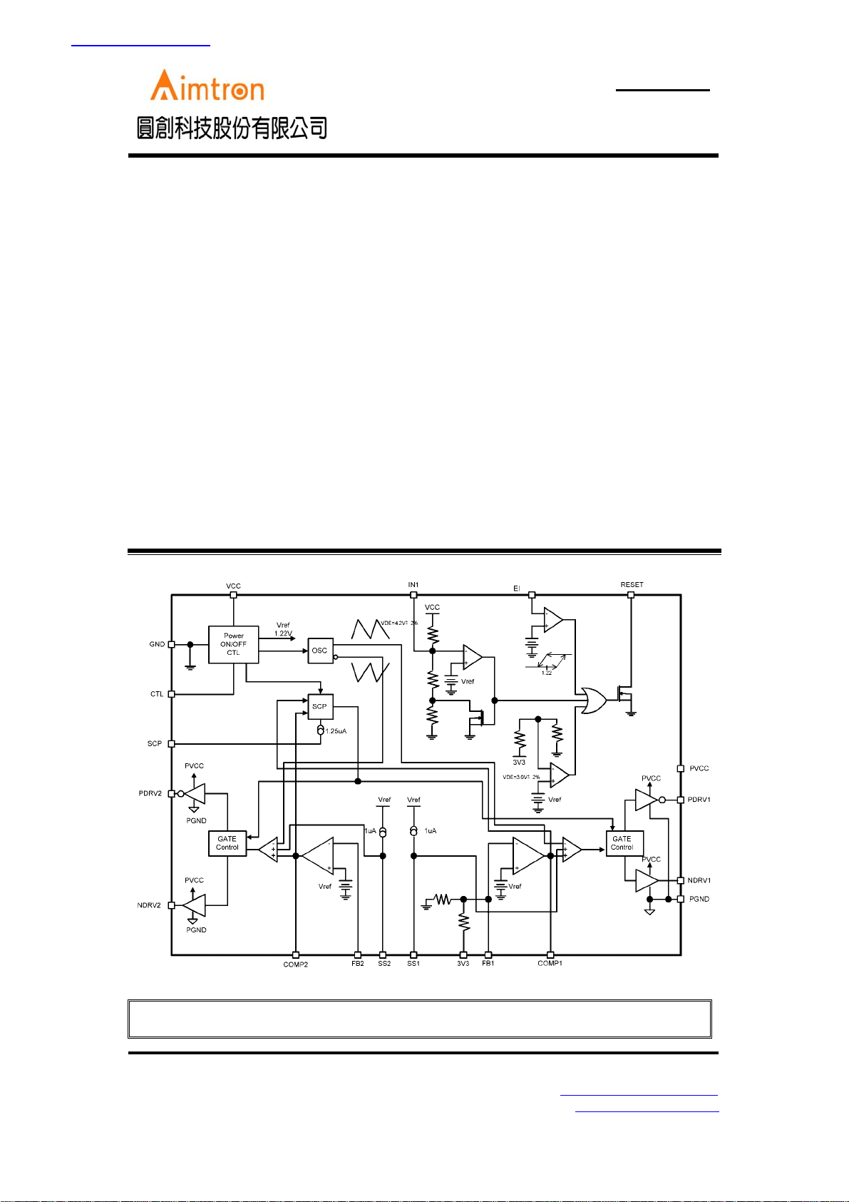
Block Diagram
General Description
The AT1369 provides complete control and
protection for a DC/DC converter optimized for
high-performance microprocessor applications. It
is designed to drive one P-Channel and one NChannel MOSFETs in a synchronous-rectified
buck topology. The AT1369 integrates all of the
control, output adjustment, monitoring and
protection functions into a single package. The
output voltage of the converter can be precisely
regulated with a maximum tolerance of ±2% over
temperature and line voltage variations. The
AT1369 is a family of low-noise synchronous stepdown DC/DC converters that is ideally suited for
systems powered from a 1-cell Li-ion battery or
from a 3-cell to 4-cell NiCd, NiMH, or alkaline
battery. It can also be used to USB-Based power
system.
Aimtron reserves the right without notice to change this circuitry and specifications.
2F, No.10, Prosperity RD. II, Science-Based Industrial Park, Hsinchu 300,Taiwan, R.O.C.
Tel: 886-3-563-0878 WWW: http://www.aimtron.com.tw
Fax: 886-3-563-0879 Email: [email protected]
1
Page 2
AT1369
Preliminary Product Information
2-Channel Synchronous Buck PWM Controller
with Power Good Reset
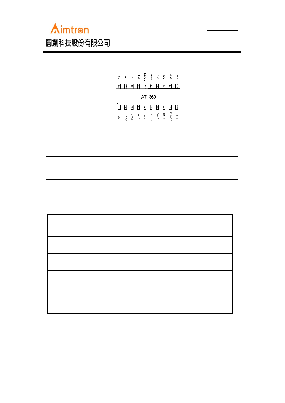
Pin Configuration
Ordering Information
Part number Package Marking
AT1369AR SSOP20 AT1369AR
AT1369AR_GRE SSOP20,Green AT1369AR, Date Code with one bottom line
AT1369BR SSOP20 AT1369BR
AT1369BR_GRE SSOP20,Green AT1369BR, Date Code with one bottom line
A: fosc =300KHz B: fosc =600KHz
Pin Description
Symbol Pin No. Descript Symbol Pin
FB1
COMP1
PVCC
PDRV1
NDRV1
NDRV2
PDRV2
PGND
COMP2
FB2
1 Inverting input to error
amplifier 1
2 Error amplifier1 output
3 Power blocks power
supply
4 Output1 for Pch-MOSFET
5 Output1 for Nch-MOSFET
6 Output2 for Nch-MOSFET
7 Output2 for Pch-MOSFET
8 Power blocks ground
9 Error amplifier1 output
10 Inverting input to error
amplifier 2
SS2
SCP
CTL
VCC
GND
RESET
IN1
EI
3V3
SS1
Descript
No.(A/B)
11 Sotf-start 2
12 Short-Circuit protection
13 Chip enable, high active
14 Control blocks power
supply
15 Control blocks ground
16 Power Good indicator
17 VCC monitor voltage
adjustable input pin
18 Adjustable Reset input
19 Output voltage 3.3V
20 Sotf-start 1
2F, No.10, Prosperity RD. II, Science-Based Industrial Park, Hsinchu 300,Taiwan, R.O.C.
Tel: 886-3-563-0878 WWW: http://www.aimtron.com.tw
Fax: 886-3-563-0879 Email: [email protected]
2
Page 3
AT1369
Preliminary Product Information
2-Channel Synchronous Buck PWM Controller
with Power Good Reset
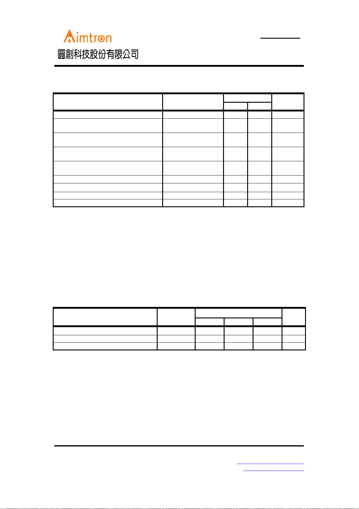
Absolute Maximum Ratings
Rated ValueParameter Condition
Unit
Min. Max.
Power Supply Voltage — - +8 V
Source Average Current of PDRV1,NDRV1
—--50mA
PDRV2,NDRV2
Sink Average Current of PDRV1,NDRV1,
—-50mA
PDRV2,NDRV2
Source Peak Current of PDRV1,NDRV1,
— - -200 mA
PDRV2,NDRV2
Sink Peak Current of PDRV1,NDRV1,
—-200mA
PDRV2,NDRV2
Input Voltage to Error Amplifier — - 6.5 V
Continuous power dissipation
SSOP20(Ta=+25℃)
Operating temperature — -30 +85
Storage temperature — -55 +125
Stresses beyond those listed under “Absolute Maximum Ratings” may cause permanent damage to the device. These are
stress ratings only, and functional operation of the device at these or any other conditions beyond those indicated in the
operational sections of the specifications is not implied. Exposure to absolute maximum rating conditions for extended
periods may affect device reliability.
-560mW
0
C
0
C
Recommended Operating Conditions
(Ta=+250C)
Va lu esParameter Symbol
Min. Typ. Max.
Power supply voltage V
Control input voltage V
Operating temperature T
CC
CTL
OP
2.5 -- 7
0--7V
-20 +25 +85 °C
2F, No.10, Prosperity RD. II, Science-Based Industrial Park, Hsinchu 300,Taiwan, R.O.C.
Tel: 886-3-563-0878 WWW: http://www.aimtron.com.tw
Fax: 886-3-563-0879 Email: [email protected]
3
Unit
V
Page 4

AT1369
Preliminary Product Information
2-Channel Synchronous Buck PWM Controller
with Power Good Reset
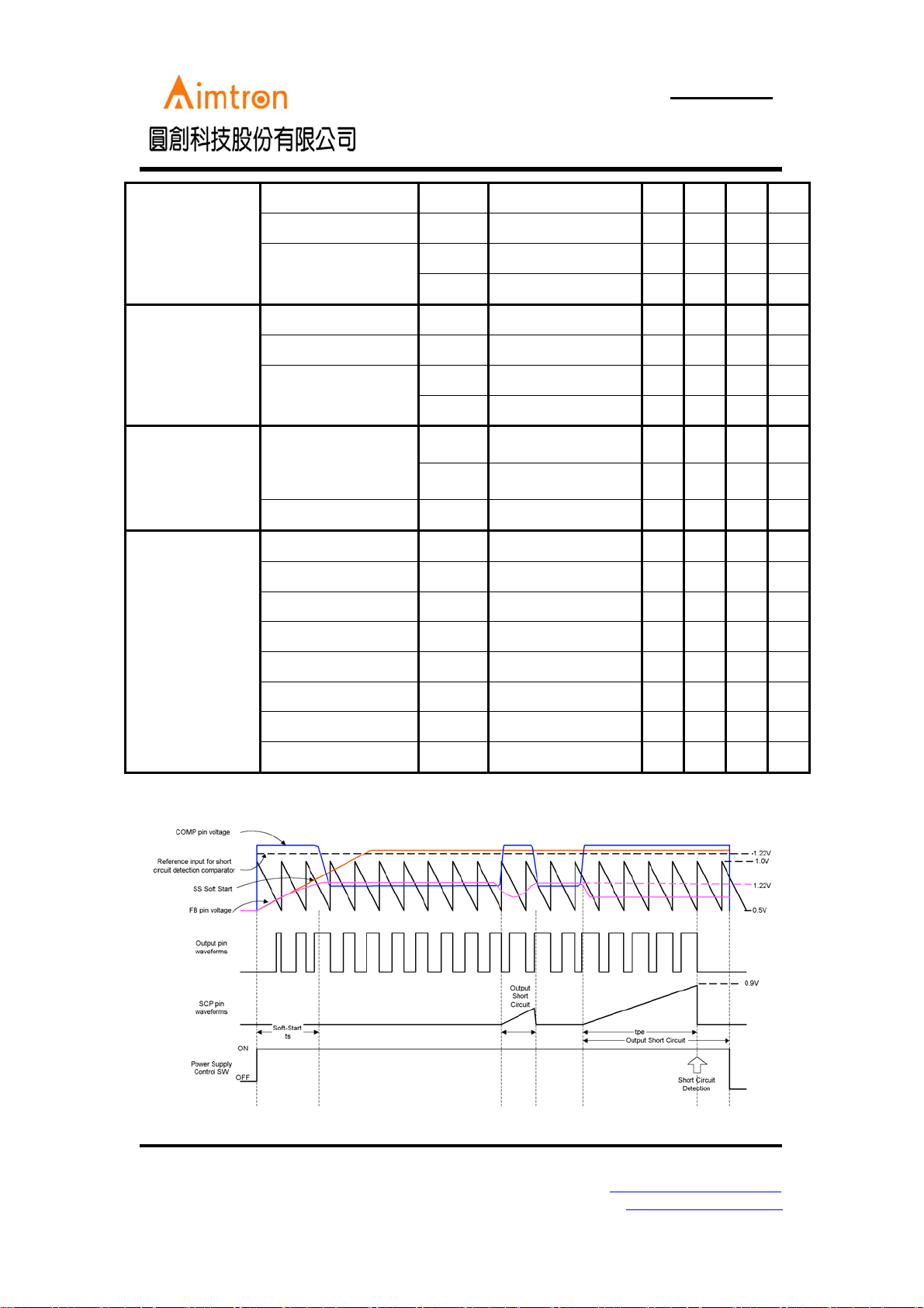
Electrical Characteristics
(VCC = 5V,Ta =+25℃ , unless otherwise noted. )
Entire device
Error amplifier
Sawtooth wave
oscillator (OSC)
Soft-Start
Short-Circuit
Input Supply Range V
Quiescent Current I
Current in standby mode I
Reference Voltage V
Reference Voltage
line-regulation
V
REF-Line
Rference Variation
with Temperature
Input Offset Voltage V
Source Current I
Sink Current I
Source current Variation
with temperature
Sink current Variation
with temperature
Unity Gain Bandwidth f
Common Mode Input
Voltage Range
V
DC Open Loop Gain A
fosc
Frequency
fosc
High Level Voltage
Low Level Voltage
Variation with Power
Supply
Variation with
temperature
Charge Current of
SS1,2
I
CSS1,2
Invalid threshold
voltage of SS1,2
Charge Current of
SCP
I
Threshold Voltage of
SCP
Min. Typ. Max.
CC
2.5 -- 7.0 V
Duty=50%,
f
=600KHz
OSC
CC
PDRV/NDRV No Load
CTL=0V
ST
Ta =-20℃ to +85℃
REF
1.20 1.22 1.24 V
VCC=2.5V to 7.0V
Ta =-20℃ to +85℃
IO
V
= V
OH
OL
V
COMP
COMP
-0.5V -1.0 -1.5 -2.0 mA
REF
= 0.5V
160 120 80
Ta =-20℃ to +85℃
Ta =-20℃ to +85℃
T
COM
V
0.2 1.5 V
AT1369A 250 300 350
AT1369B 500 600 700
Vcc=2.5V to 7V 2
Ta =-20℃ to +85℃
-1.5 -1.0 -0.8
CSCP
-1.7 -1.25 -1.0
Va lu esParameter Symbol Condition
Unit
1.5 2.0 mA
10
µA
110mV
0.5 1.5 %
10 mV
μA
20 %
20 %
10.0 MHz
110 dB
KHz
KHz
1.0
0.5
7%
µA
1.0 V
µA
0.9 V
V
V
%
2F, No.10, Prosperity RD. II, Science-Based Industrial Park, Hsinchu 300,Taiwan, R.O.C.
Tel: 886-3-563-0878 WWW: http://www.aimtron.com.tw
Fax: 886-3-563-0879 Email: [email protected]
4
Page 5
AT1369
Preliminary Product Information
2-Channel Synchronous Buck PWM Controller
with Power Good Reset
PDRV1,2 Output
Block
NDRV1,2 Output
Block
Control Block
Output source current I
Output sink current I
Output ON resistor
Output source current I
Output sink current I
Output ON resistor
CTL input voltage
CTL input Current I
source
R
R
source
R
R
V
V
CTL
Duty≥95% PDRV=0V
Duty≤5% PDRV=5V
sink
PDRV=-15mA
OH
PDRV=15mA
OL
Duty≥95% NDRV=0V
Duty≤5% NDRV=5V
sink
NDRV=-15mA
OH
NDRV=15mA
OL
Active mode VCC-
IH
Standby mode
IL
CTL=5.0V
- -130 -80 mA
65 100 mA
10 20
10 20
- -130 -80 mA
65 100 mA
10 20
10 20
1
0
VCC V
VCC/
20
Ω
Ω
Ω
Ω
V
2
µA
RESET Monitor
Block
VCC reset ON voltage V
VCC reset hysteresis V
3V3 reset ON voltage V
3V3 reset hysteresis V
EI reset ON voltage V
EI reset hysteresi V
RSTON1
RSTON1 hys
RSTON2
RSTON2 hys
RSTON3
RSTON hys
Reset output voltage V
Reset leakage current I
OL
Leak
IL =1mA
4.10 4.20 4.30 V
-100 100 mV
2.94 3.0 3.06 V
-60 60 mV
1.12 1.22 1.32 V
-100 - 100 MV
0.4 V
2.0
µA
2F, No.10, Prosperity RD. II, Science-Based Industrial Park, Hsinchu 300,Taiwan, R.O.C.
Tel: 886-3-563-0878 WWW: http://www.aimtron.com.tw
Fax: 886-3-563-0879 Email: [email protected]
5
Page 6
AT1369
Preliminary Product Information
2-Channel Synchronous Buck PWM Controller
with Power Good Reset
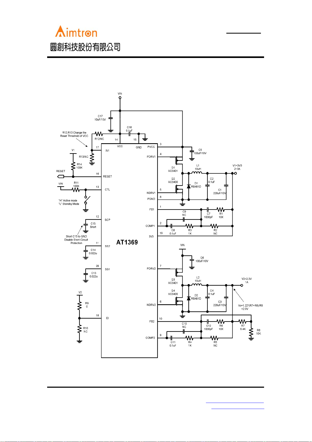
Typical Application Circuit: 3V3 and 2V Output
2F, No.10, Prosperity RD. II, Science-Based Industrial Park, Hsinchu 300,Taiwan, R.O.C.
Tel: 886-3-563-0878 WWW: http://www.aimtron.com.tw
Fax: 886-3-563-0879 Email: [email protected]
6
Page 7
AT1369
Preliminary Product Information
2-Channel Synchronous Buck PWM Controller
with Power Good Reset
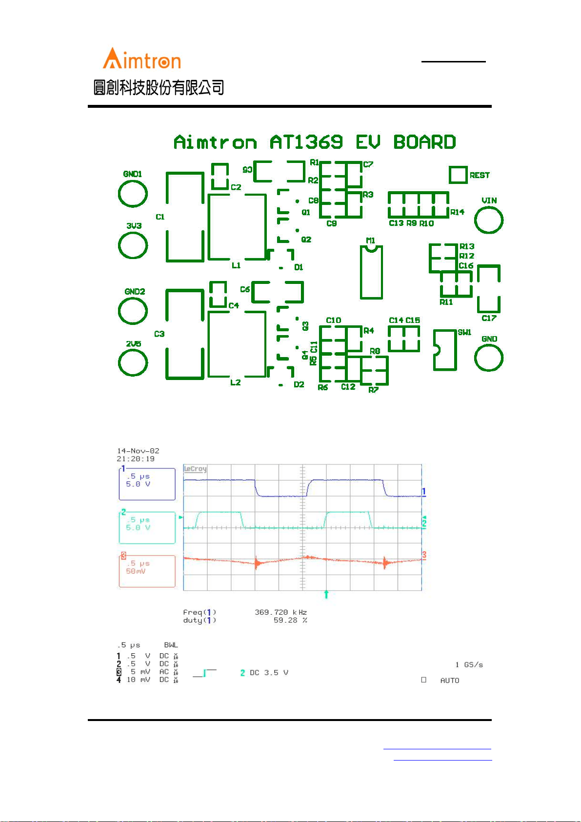
CH1:PDRV2 CH2:NDRV2 CH3:Output 2.0V/1A(AC ripple)
Fig1. Input 5V, Output 2.0V/1A
2F, No.10, Prosperity RD. II, Science-Based Industrial Park, Hsinchu 300,Taiwan, R.O.C.
Tel: 886-3-563-0878 WWW: http://www.aimtron.com.tw
Fax: 886-3-563-0879 Email: [email protected]
7
Page 8
AT1369
Preliminary Product Information
2-Channel Synchronous Buck PWM Controller
with Power Good Reset
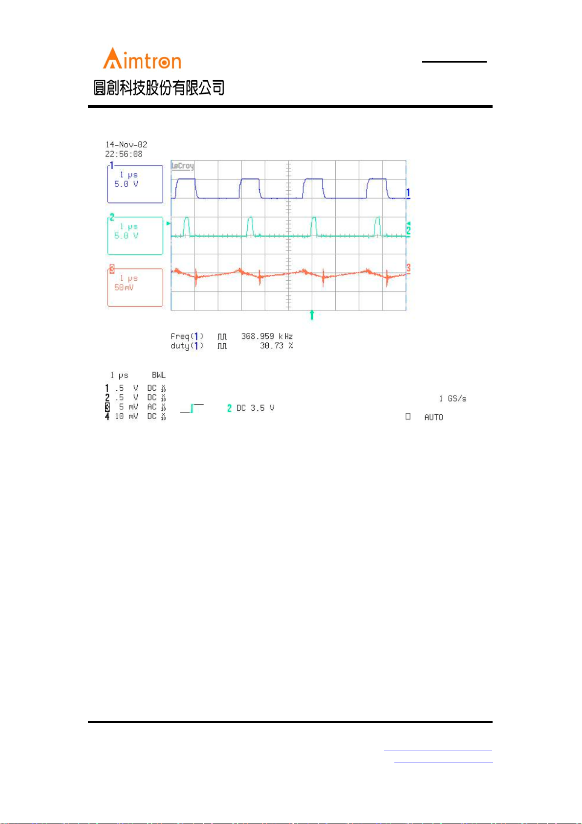
CH1:PDRV1 CH2:NDRV1 CH3:Output 3.3V/2A(AC ripple)
Fig2. Input 5V, Output 3.3V/2A
2F, No.10, Prosperity RD. II, Science-Based Industrial Park, Hsinchu 300,Taiwan, R.O.C.
Tel: 886-3-563-0878 WWW: http://www.aimtron.com.tw
Fax: 886-3-563-0879 Email: [email protected]
8
Page 9
AT1369
Preliminary Product Information
2-Channel Synchronous Buck PWM Controller
with Power Good Reset
2F, No.10, Prosperity RD. II, Science-Based Industrial Park, Hsinchu 300,Taiwan, R.O.C.
Tel: 886-3-563-0878 WWW: http://www.aimtron.com.tw
Fax: 886-3-563-0879 Email: [email protected]
9
Page 10
AT1369
Preliminary Product Information
2-Channel Synchronous Buck PWM Controller
with Power Good Reset
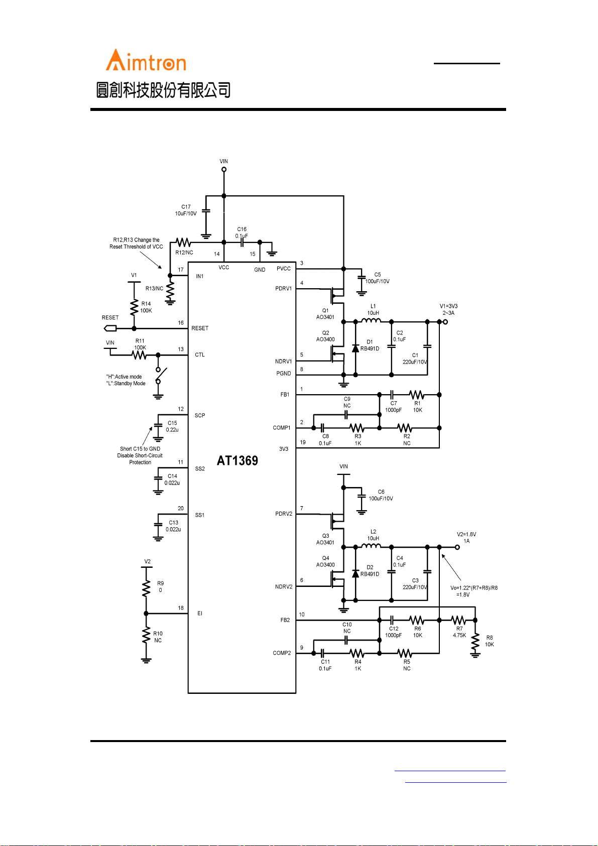
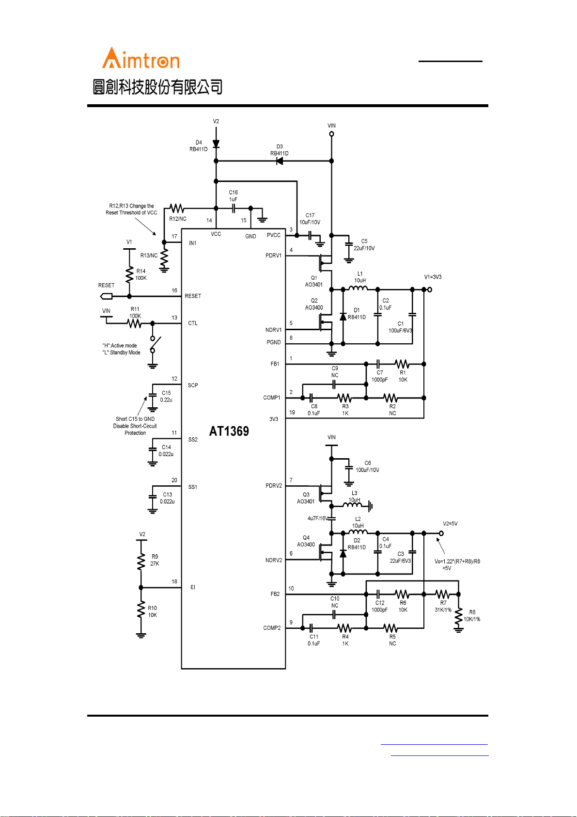
Vin=4 cell AA Battery
2F, No.10, Prosperity RD. II, Science-Based Industrial Park, Hsinchu 300,Taiwan, R.O.C.
Tel: 886-3-563-0878 WWW: http://www.aimtron.com.tw
Fax: 886-3-563-0879 Email: [email protected]
10
Page 11
AT1369
Preliminary Product Information
2-Channel Synchronous Buck PWM Controller
with Power Good Reset
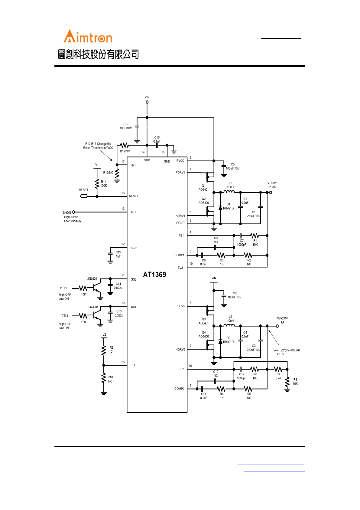
How to control CH1 and CH2 ON/OFF:
2F, No.10, Prosperity RD. II, Science-Based Industrial Park, Hsinchu 300,Taiwan, R.O.C.
Tel: 886-3-563-0878 WWW: http://www.aimtron.com.tw
Fax: 886-3-563-0879 Email: [email protected]
11
Page 12
AT1369
Preliminary Product Information
2-Channel Synchronous Buck PWM Controller
with Power Good Reset
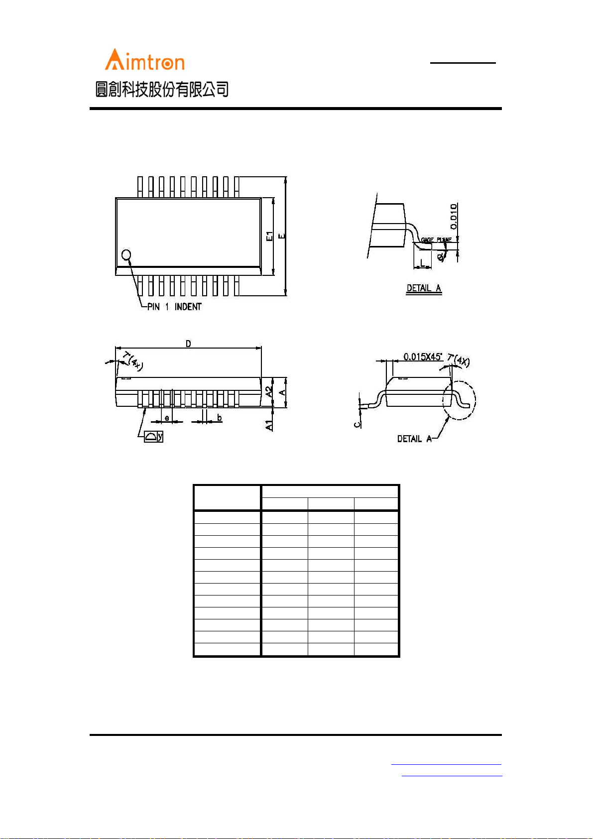
Package Outline 20-pin SSOP
SYMBOL
A 1.35 1.63 1.75
A1 0.10 0.15 0.25
A2 - - 1.50
b 0.20 - 0.30
C 0.18 - 0.25
D 8.56 8.66 8.74
E 5.79 5.99 6.20
E1 3.81 3.91 3.99
L 0.41 0.635 1.27
e - 0.635 -
y--0.076
θ 0° 8°
2F, No.10, Prosperity RD. II, Science-Based Industrial Park, Hsinchu 300,Taiwan, R.O.C.
Tel: 886-3-563-0878 WWW: http://www.aimtron.com.tw
Fax: 886-3-563-0879 Email: [email protected]
MILLIMETERS
MIN TYP MAX
12
 Loading...