

Page 1

FEATURES
“This La ser Product is d esignated as C lass 3R during al l procedures o f operation”.
“Laser L ight-Avoid Dire ct Eye Exposure ”.
• Made of ano dized aircra ft grade alumi num
• Red <5mW lase r
• Windag e and elevation ad justment
• Excelle nt for quick tar get acquisit ion
• 500M ran ge
SPECIFICATIONS
WAVELENGTH 635-6 55nm
BATTERY CR123A
OPERATING TEMPERATURE 35-90F
RANGE 500M
COMPLIES WITH FDA
PERFORMANCE
STANDARDS FOR
LASER PRODUCTS
EXCEPT FOR
DEVIATIONS
PURSUANT TO LASER
NOTICE NO. 50, DATED
JUNE 24, 2007
AIM SPORTS INC.
1321 E. CHIEF PRIVADO
ONTARIO, CA 91761
PROD #: XXXXX
LOT #: AIM13-XXXXX
LASER LIGHT
AVOID DIRECT EYE EXPOSURE
CLASS 3R LASER PRODUCT
635-655nm <5mW CW
EN/IEC 60825-1 2007
AIM SPORTS INC. WARRANTY
LIMIT ED LIFETIME WARR ANTY - USA & CANADA O NLY
The Aim Sp orts Inc. Limi ted Lifetime War ranty covers a gainst defect s in materials a nd workmansh ip.
Aim Spor ts Inc. will rep lace or repair d efective pro duct(s) upon insp ection by our tec hnical staf f. Defects
or damage f rom abnormal u se, improper st orage, unautho rized modifi cations, unau thorized rep air,
misuse, ne glect, abus e, alteration or i mproper inst allation will v oid the produc t(s) warranty and e ligibilit y.
Limited L ifetime Warran ty covers item(s) pu rchased from a n authorized de aler, within the fi rst 90 days
of owners hip, with proof of r eceipt purc hase (duplicat ions only). Aim Spo rts Inc. will w aive the $10.00
shippi ng and handlin g fee for returned p roduct(s). Returne d items over 90 days o f ownership or n o proof
of recei pt purchase pr ior to 90 days, a $10.00 fee w ill apply to cove r shipping an d handling char ges.
Make che cks or money orde rs payable to: Aim S ports Inc.
RETURNING ITEMS
Before shi pping item(s) bac k to Aim Sports In c. a Return Autho rization Numb er (RA#) must be ob tained
by callin g Technical Assi stance. All ret urn item(s) must be re ceived with R A#. There will be a del ay in
proces sing for all item (s) received with out RA#.
DO NOT ATTEMPT TO SHIP YOUR PRODUCT BACK WITHOUT FIRST
1321 E. Chief Privado, Ontario, CA 91761
WE WILL REPLACE OR REPAIR ANY DEF ECTIVE ITEM THAT IS PURCHASED OR MANUFACTURED BY AI M SPORTS INC.
IMPORTANT NOTICE!
CONTACTING OUR TECH NICAL ASSISTANCE:
AIM SPORTS INC.
TECHNICAL ASSISTANCE
Telephone: (8 55) ASK-4AIM
E-mail: RMA@aimsportsinc.com
Downloadable PDF Version Online
AIMSPORTSINC.COM
RED LASERS
Quick Start Manual
Page 2
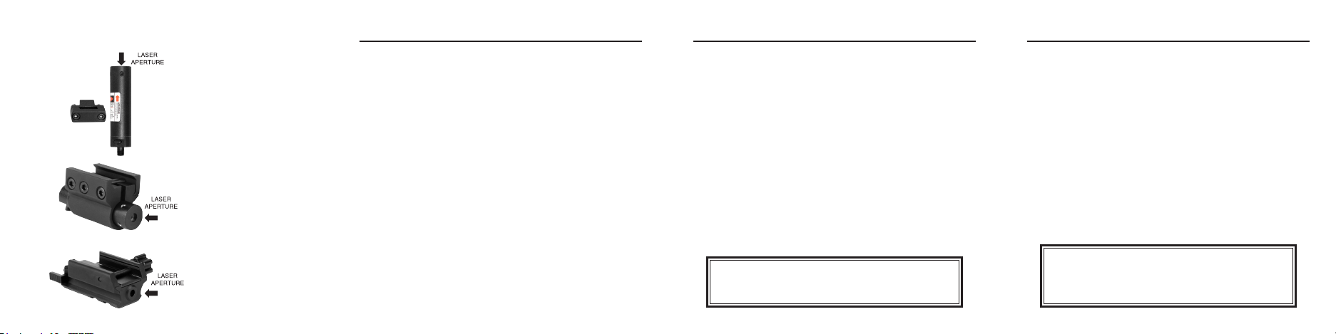
RED LASERS
Pistol Laser Sight
Pistol/Rifle Laser Sight
Tactical Red Laser
LH001
LH002
LH003
LH001 INSTRUCTIONS
INSTALLI NG LASER
1. Your laser come s with both a wire p ressure switc h and a toggle swi tch end cap. Uns crew the end
cap that c ame already at tached to the la ser, and insert t he three batter ies provide d into the tube.
Make sure th e + side is facin g up on each batte ry.
2. Select t he end cap one you w ould like to use, and i nstall it by scr ewing it onto the r ear end of the lase r.
The laser c an be activat ed by sliding the t oggle bar or pre ssing the wire p ressure pad.
3. Loosen t he thumbscre w located on the r ight side of the m ount until the la ser body is abl e to slide
inside of i t.
4. Locate t he trigger gua rd mount, and uns crew and remove th e two hex screws w ith the provid ed
wrench.
5. Place th e half of the mount w ith the threade d hole in the cent er on the front of the t rigger guard , and
the other h alf behind.
Note: Ther e 10 plastic shims of d ifferent size s included in th e kit to be used to c ompensate for t he
angle of th e trigger guar d if needed. If ne eded, selec t the appropr iate sized shim, a nd insert it be hind
the trig ger guard and int o the face of the bac k half of the moun t. There are round d imples in the
mount tha t mate with the rai sed circular b umps on the shim t hat fit togethe r.
7. Re-insert a nd tighten the hex s crews with the w rench provid ed to secure the t wo halves of the mo unt
to the trig ger guard.
8. Screw th e laser into the th readed hole on t he front of the moun t.
ADJUST ING LASER
1. To adjust the las er, locate the hex sc rews located o n the bottom and l eft side of the fr ont of the laser.
2. To adju st the elevatio n up, tighten the he x screw with the pr ovided wrenc h by turning it cl ockwise. To
lower the b eam, turn the sc rew counter clo ckwise.
3. To adjust the w indage to the ri ght, turn the hex sc rew on the left si de clockwi se. To move the beam to
the left , turn the screw c ounter clock wise.
LH002 INSTRUCTIONS
INSTALLI NG LASER
1. Your laser come s with both a wire p ressure switc h and a toggle swi tch end cap. Uns crew the end
cap that c ame already at tached to the la ser, and insert t he three batter ies provide d into the tube.
Make sure th e + side is facin g up on each batte ry.
2. Select t he end cap one you w ould like to use, and i nstall it by scr ewing it onto the r ear end of the lase r.
The laser c an be activat ed by sliding the t oggle bar or pre ssing the wire p ressure pad.
3. Loosen t he thumbscre w located on the r ight side of the m ount until the la ser body is abl e to slide
inside of i t.
4. Locate t he two small hex sc rews on the front o f the laser, and ensu re that one is posi tioned on the
bottom o f the laser, and one is p ositioned on t he left side. Th is will allow you to a ccess these
adjustm ent screws for s ighting in your la ser later.
5. Slide th e mount onto the ac cessory ra il into the desir ed position
6. Tighte n the hex screws wi th the wrench pr ovided. to sec ure the mount to the r ail.
ADJUST ING LASER
1. To adjus t the laser, locate t he hex screws lo cated on the bot tom and left si de of the front of the l aser.
2. To adjust the el evation up, tigh ten the hex screw w ith the provide d wrench by turn ing it clock wise. To
lower the b eam, turn the sc rew counter clo ckwise.
3. To adj ust the windag e to the right, tur n the hex screw on the l eft side clo ckwise. To move the b eam to
the left , turn the screw c ounter clock wise.
Do not over tighten the screws or you may strip the
threaded holes. Stripped holes are NOT covered by warranty.
CAUTIO N
LH003 INSTRUCTIONS
INSTALLI NG LASER
1. Loosen the t humb screw loc ated on the righ t side of the laser ( laser pointi ng down range), and s lide it
onto the ac cessory ra il into the desir ed position.
2. Tighten t he thumbscre w to secure the mou nt to the rail, usin g a coin or screwd river if desire d.
3. The lase r can be activa ted by sliding th e toggle bar loc ated at the rear e nd of the laser bac k and forth.
4. The batt ery can be acc essed by loos ening the batt ery cap loca ted on the botto m of the laser with a
coin or sc rewdriver.
ADJUST ING LASER
1. To adjust the win dage, turn the hex s crew located o n the left front s ide of the laser. To move it to t he
right, tu rn the screw clo ckwise wit h the provided w rench. To move it to the le ft, turn the scr ew counter
clock wise.
2. To adjust the el evation, turn th e hex screw loca ted on the botto m of the laser. To move the bea m up,
turn the s crew clockw ise. To move it down, tur n it counter clo ckwise.
Use of controls or adjustments or performance of procedures
other than those specified herein may result in hazardous
CAUTIO N
radiation exposure.
 Loading...