

Page 1

FIBER OPTIC AND
TRI-ILLUMINATED
Downloadable PDF Version Online
1 1
SCOPES
Quick Start ManualAIMSPORTSINC.COM
Page 2

Contents
Scope Parts ..................................................................................... 1
Scope Installation ............................................................................7
Focusing Reticle ............................................................................ 10
Adjusting Back Up Sight ................................................................ 11
Adjusting Windage & Elevation ..................................................... 13
Understanding Parallax .................................................................16
Illuminating the Reticle .................................................................. 17
Changing Batteries ........................................................................19
AIM Means Minimal Maintenance .................................................21
Troubleshooting .............................................................................23
Specifications ................................................................................ 25
Reticles ..........................................................................................26
About Us ........................................................................................ 30
AIM Sports Lifetime Warranty ....................................................... 31
Warranty Form
If you experience any problems with our products, please enclose this form
with an explanation of the problem and mail it to:
AIM SPORTS INC.
1321 E. Chief Privado
Ontario, CA 91761
Item Number: __________________________________________________
Purchased Date: _______________________________________________
Dealer/Distributor: ______________________________________________
Your Name: ___________________________________________________
Address: ______________________________________________________
City: _________________________________________________________
Phone: _______________________________________________________
Brief Remark/Description of Problem: ______________________________
______________________________________________________________
Return Authorization Number: ____________________________________
Warran ty forms are als o available on line at aimspo rtsinc.co m
Page 3

AIM SPORTS INC. WARRANTY
LIMITED LIFETIME WARRANTY
The Aim Sp orts Inc. Lim ited Lifetime Warrant y covers against defec ts in material s
and workmanship. Aim S ports Inc. wi ll replace or repair def ective produ ct(s) upon
inspe ction by our technica l staff. Defect s or damage from a bnormal use, imprope r
storag e, unauthorize d modifications, un authorized re pair, misuse, negl ect, abuse,
altera tion or improp er installati on will void the produc t(s) warranty and e ligibilit y.
Limite d Lifetime Warra nty covers item(s) purcha sed from an autho rized dealer, wi thin
the first 90 days o f ownership, wi th proof of recei pt purchase (duplica tions only). Aim
Spor ts Inc. will waiv e the $10.00 shipping and handling fe e for returned pr oduct(s).
Returne d items over 90 days of owner ship or no proof of r eceipt purch ase prior to 90
days, a $10.00 fe e will apply to cover ship ping and handling charges. M ake checks or
money or ders payable to: Aim Spor ts Inc.
RETURNING ITEMS
Before sh ipping item(s) bac k to Aim Sports Inc. a Retu rn Authorizat ion Number (RA#)
must be o btained by calling Technical As sistance. Al l return item(s) must b e received
with RA #. There will be a delay in pro cessing for al l item(s) received w ithout RA#.
DO NOT ATTEM PT TO SHIP YOUR PRODUCT BACK WITHOU T FIRST
CONTACTIN G OUR TECHNICAL ASSIS TANCE:
31
IMPORTANT NOTICE!
Telephon e: (855) ASK-4AI M
E-mail: RMA@aimsportsinc.com
KNOW YOUR SCOPE
Riflescopes have become far more sophisticated over the years, but the
four most basic parts have remained the same.
Workings from front to back are:
1. The objective lens (or front lens) is critical to a superior sight picture.
2. The internal erector lenses which rights the image.
3. The reticle, often referred to as the crosshair, provides the aiming point.
4. The ocular lens (or eyepiece lens) works with the other lenses to magnify
the image, provide correct eye relief, and make diopter corrections.
HOW SCOPES WORK
As light passes through and beyond the objective lens, the resulting
upside down image is sent to the internal lenses. Known as erector lenses,
these internal lenses return the image to a right-side-up position. Finally,
the ocular lens makes a final enlargement of that image and sends it on
to your eye. Your AIM scope was designed, manufactured, and tested to
ensure that, when properly mounted and sighted-in on your firearm, you
will enjoy exceptional performance. A solid mount is critical to satisfactory
performance of your scope. If you have problems or questions, please
contact AIM Technical Assistance (see page 35).
Page 4

SCOPE PARTS
(MODELS JTDFO432G & JTCFO432G)
1. Objective Lens
2. Elevation Turret
3. Windage Turret
4. Illumination Dial
5. Tube
6. Ocular Lens
Always check and be certain that the firearm is unloaded
before undertaking any work upon it.
11 30
7. Accessory Rail
8. Illumination Battery
Cap
9. Base Mount
10. Front Sight
11. Rear Sight
CAUTIO N
ABOUT US
Established in 2007, AIM SPORTS INC. first made its appearance in the
firearm’s accessory industr y by doing private label production for several
major manufacturers and retailers. During that period, AIM Sports began
receiving requests from numerous dealers and distributors for access to
the affordable, high quality products that Aim was capable of producing.
By soliciting feedback from both clients and end users, AIM was able to
overcome the challenges a new company often faces when entering a
global market and industry, especially one as competitive as the shooting,
hunting, and outdoors industr y. As AIM continues to grow and expand, it
constantly works to improve and find better ways to develop new products
that will surpass not only its own expectations, but also the expectations of
the consumer.
AIM’s Research and Development team, with over 10 years of experience,
continuously strives to improve and develop new products for the
company. AIM has expanded its original product line of optics, mounts,
and accessories to include products designed to enhance a wide variety
of firearms used by armed forces around the world, including some of the
latest and most innovative platforms that firearms industry offers.
Customer service and constant dedication to its clients sets AIM SPORTS
apart in the industry. Backed by a Lifetime Warranty, you can purchase and
use AIM products with confidence.
Page 5
RAPID RANGING RETICLE
The Rapid Ranging Reticle is designed specifically to enhance a shooter’s
long range accuracy and ranging capabilities under a variet y of field
conditions and allows for instant ranging of targets. Mid-weight posts stand
out against cover and thin crosshairs keep from obscuring your view of
the target. This reticle is calibrated for .223 Remington 55gr. bullet.
2
11
6
1
9
5
10
4
3
8
7
229
Page 6

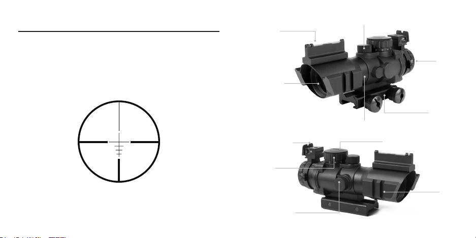
SCOPE PARTS
(MODELS JTDSR432G & JTDTR432G)
1. Objective Lens
2. Elevation Turret
3. Windage Turret
4. Illumination Dial
5. Tube
6. Ocular Lens
7. Accessory Rail
8. Illumination Battery
Cap
12. Base Mount
3/4 CIRCLE RETICLE
The 3/4 Circle Reticle is designed specifically to enhance a shooter’s
accuracy and capabilities under a variety of field conditions, both long and
close range. This reticle is not calibrated for a specific caliber.
Always check and be certain that the firearm is unloaded
before undertaking any work upon it.
3 28
CAUTIO N
Page 7

ARROW RETICLE
The Arrow Reticle is designed specifically to enhance a shooter’s accuracy
and ranging capabilities under a variety of field conditions, both long and
close range. Mid-weight crosshairs stand out against cover and chevron
keeps you right on target. This reticle is not calibrated for a specific caliber.
2
6
1
5
8
4
3
9
7
427
Page 8

SCOPE PARTS
(MODELS JTCTQ432G, JTDTRQ432G & JTHTQ432G)
1. Objective Lens
2. Elevation Turret
3. Windage Turret
4. Illumination Dial
5. Tube
6. Ocular Lens
7. Accessory Rail
8. Illumination Battery
Cap
12. Base Mount
AIM SPORTS RETICLES
A reticle is a grid or pattern placed in the focal plane of an optical
instrument, used to assist in establishing scale or position of objects under
observation. All AIM Sports reticles are designed to enhance a shooter’s
long range accuracy and ranging capabilities under a variet y of field
conditions. Most AIM Sports reticles are laser etched, ensuring a clear
reticle in your field of view with no distortion. Below the reticles that are
available with these AIM Sports Scopes.
ARROW 3/4 CIRCLE
Always check and be certain that the firearm is unloaded
before undertaking any work upon it.
5 26
CAUTIO N
RAPID RANGING
Page 9

SPECIFICATIONS
MAGNIFICATION
TUBE DIAMETER
OBJECTIVE
EYE RELIEF
EXIT PUPIL
FOV (feet at 100 yds.)
MOA
FINISH
LENS COATING
BAT TERY
LENGTH
WEIGHT
JTCFO432G
JTDFO432G
4X
30 mm
32 mm
3.5”
8 mm
36.6
1/4
Matte Black
Green
CR2032
6”
16.09 oz.
JTDSR432G
JTDTR432G
JTCTQ432G
JTDTRQ432G
JTHTQ432G
4X
30 mm
32 mm
3.5”
8 mm
36.6
1/4
Matte Black
Green
CR2032
6”
11.4 oz.
2
6
1
9
5
8
4
7
3
625
Page 10

SCOPE INSTALLATION
4. Be sure to use factor y-loaded ammunition of the same bullet type,
weight, and preferably, lot number. If one type of ammunition does not
shoot well, try another brand or bullet weight.
YOUR SCOPE IS DESIGNED TO MOUNT TO ANY
WEAVER / MIL STD PICATINNY 1913 RAIL
5. Be certain that both the barrel and chamber are clean. Heavy
factory grease or copper fouling in a barrel can diminish the accuracy of
the firearm.
FOR SCOPES EQUIPPED W/ THUMB SCREWS
(MODELS JTCFO432G, JTDFO432G, JTDSR432G & JTDTR432G)
1. Loosen the thumb screws on the mount base, and place it on the rail
where desired. Make sure the scope base is sitting flush on the rail,
and is not canted.
2. Tighten the thumb screws by hand, and check the eye relief on the
scope to ensure that the scope is mounted in the optimal position.
3. Using a standard screwdriver or a coin, complete the final tightening
of the thumb screws to ensure that the scope is secure to the rail. Don’t
overtighten screws. You may use thread locking compound if desired in
order to help avert loosening of the thumb screws due to recoil.
7 24
Page 11

TROUBLESHOOTING TIPS
FOR SCOPES EQUIPPED W/ QUICK RELEASE MOUNT (QRM)
(MODELS JTCTQ432G, JTDTRQ432G & JTHTQ432G)
Before you ship a scope back to the factory for service or repair, please
check the following items.
1. Check the mount. Make sure the scope is mounted securely to the rifle.
Try, with bare hands only, to gently twist the scope in the rings or see if
anything moves when you jiggle it. If there is any movement, re-tighten the
mounting system according to mounting instructions.
2. Make sure the action of your rifle is properly bedded in the stock, and
that all receiver screws are tight and have been tightened in the sequence
recommended by the manufacturer. A loosely fitted stock can cause
changes to the point-of-impact.
3. When test firing a rifle to check the point-of-impact relative to windage
and elevation adjustments, be sure to fire from a solid bench with sandbags
supporting the forearm and buttstock.
1. Move the QRM lever arm forward into the “open position.” (Fig 1)
2. On the opposite side of the scope (left side if looking through the
eyepiece) is a nut with an allen screw located in the center of the base.
Remove the nut. (Fig 2)
3. Next, loosen the allen screw with the allen wrench provided. Do not
remove. (Fig 2)
4. Place the scope onto any standard weaver/mil std. Picatinny 1913 rail in
the desired location relative to your eye relief. Make sure the mount is
flush to the rail and not canted.
5. Tighten the allen screw with the allen wrench until the screw is snug. Do
not over tighten.
6. Attempt to close the QRM lever. It should be tight and not easy to close,
but should not need to be forced. If it is too tight and difficult to close,
slightly loosen the allen screw until you are able to close the QRM lever
and the base is tight to the rail.
7. Once the base is securely mounted to the rail in the desired position,
replace the nut over the allen screw and tighten with a standard wrench.
This nut is to help prevent the allen screw from loosening due to recoil.
23 8
Page 12

Figure 1: Move the QRM lever arm into the open position.
SEALS
AIM scopes are sealed from within by several methods, including O-rings.
All seals are permanent and require no maintenance.
SCOPE EXTERIOR
AIM scopes are made of rugged 6061-T6 aircraf t aluminum alloy. No
maintenance of any kind is required; simply wipe off any dirt or fingerprints
that accumulate with a clean, dry cloth.
POWER SELECTOR RING
(ON VARIABLE POWER SCOPE)
No Lubrication is ever required on the power selector ring. DO NOT
LOOSEN OR REMOVE THE HEX-HEAD SCREW IN THE POWER
SELECTOR RING.
ADJUSTABLE OBJECTIVE/SIDE PARALLAX DIAL
No lubrication is required.
Figure 2: Remove base mount nut and loosen screw.
Do NOT remove screw.
9 22
Page 13

AIM MEANS MINIMAL MAINTENANCE
FOCUSING RETICLE
AIM scope lenses are coated to reduce light reflections and light scattering,
thus increasing light transmission through the scope. They should be
cleaned as carefully as you would a camera lens. Begin by using a lens
brush to remove dust and then pure alcohol, high-grade glass cleaner or
pure water on a cotton swab.
WINDAGE/ ELEVATION ADJUSTMENTS
These adjustments are permanently lubricated. There is no need to
lubricate them. Keep the turret caps on, except when adjusting, to keep out
dust and dirt. (It’s worth noting that, unlike competitive brands, AIM scopes
are waterproof even without the caps in place.)
EYEPIECE ADJUSTMENT
This adjustment is permanently lubricated. There is no need to lubricate it.
The eyepiece can be rotated as far as it will go in either direction. It will not
detach from the scope as there is an internal lock ring.
Secure the scope and firearm in a firm rest. Safely point the scope at a
light colored background object. With the scope approximately four inches
from your eye the reticle should appear sharp and crisp; if it does not, it is
necessary to adjust the focus by means of the eyepiece.
1. If you tend to hold things away from yourself to see them clearly (you
are farsighted) turn the eyepiece counterclockwise a couple of turns. If
you hold things close to yourself to see them clearly (you are
nearsighted) turn the eyepiece clockwise a couple of turns.
2. Looking through the scope when pointed at the sky, take a few quick
glances at the reticle. The focus of the reticle should be noticeably
different from when you started. Continue this process until the reticle
appears clear and sharp.
21 10
Page 14

ADJUSTING BACK UP SIGHT
(MODELS JTCFO432G & JTDFO432G)
Your scope comes with a set of back up “iron sights” located on top of the
scope. The front sight is a fixed “fiber optic” sight that illuminates when
exposed to external light. The rear sight is adjustable for both windage and
elevation, and can be adjusted following these steps.
TO ADJUST WINDAGE:
1. Using a small standard screwdriver, turn the screw located on the right
side of the rear sight (looking downrange) clockwise to move the sight to
the right. The sight is labeled with a letter “r” and an arrow pointing to
the clockwise direction.
2. Turn the screw counter-clockwise to move the sight to the left.
TO ADJUST ELEVATION:
1. Using the provided allen wrench, loosen the hex screw located in the
top center of the rear sight. Loosen the screw only until the sight may be
moved for ward and backward – do not remove.
This can be done in t wo ways:
a. Grasp the edges of the bat tery between the thumb and forefinger and
lift it free of the dial.
OR
b. Turn the scope so that the illumination dial faces downward and
gently tap the eyepiece against the edge of your palm.
3. Insert the new battery, positive (+) side up.
4. Replace the battery cover on the illumination dial and turn it clockwise
until it is secure while holding the sides of the illumination dial to keep the
entire dial from turning.
Replacement 3-volt lithium batteries:
CR2032
There may be other lithium batteries that are acceptable with your AIM
Illuminated Reticle scope. Check with your local retailer for other options.
11 20
Page 15

CHANGING SCOPE BATTERY
All AIM Illuminated Reticle scopes use a 3-volt lithium photo batter y.
1. Remove the battery cover by grasping its edge (located around the
top of the illumination dial) and twisting the cover counterclockwise
while holding the sides of the illumination dial to keep the entire dial
from turning.
2. Remove the old battery from its position in the center of the dial.
The battery for the AIM Illuminated Reticle is located
inside the control dial and can be changed without tools.
2. With the sight able to be moved, position the sight forward or backwards
until the sight is in the desired position. Once it is “zeroed,” re-tighten
the screw so that it will not move. Do not over tighten.
*NOTE*
The rear sight assembly is held onto the scope eyepiece using a band
with two hex screws. The sight is not zeroed from the factory and it may
be necessary to rotate the rear sight assembly on the eyepiece in order to
correctly align it with the front sight. If it needs to be aligned, use the allen
wrench provided with your scope to slightly loosen the hex screws, move
the sight into the desired position, and then re-tighten the screws.
19 12
Page 16

ADJUSTING WINDAGE AND ELEVATION
ADJUSTING ELEVATION
1. Unscrew the cap located on top of the elevation adjustment dial. (Fig 1)
2. Turn the dial counter clockwise (noted on the dial as up with an arrow
pointing to the left) in order to raise the elevation/point of impact. (Fig 2)
3. Turn the dial clockwise to the right to lower the elevation.
4. Replace the cap to protect the dials from being moved out of alignment.
Figure 1 Figure 2
To illuminate the reticle:
1. Grasp the illumination dial located on left side of scope, when scope is
pointing down range.
2. Turn the dial clockwise from the OFF position to the first number
indicated on the dial.
3. View the target through the scope to determine if the reticle is bright
enough to stand out clearly against the target.
To preserve the life of the battery, always remember to turn the illumination
dial to the OFF position when the scope is not in use. For prolonged
storage, remove the batter y.
If the reticle fails to illuminate or appears dim even on the highest
illumination setting, it is necessar y to change the battery.
WARNING: Always check to ensure that the firearm is unloaded before
changing the battery in the scope.
1813
Page 17

ILLUMINATING THE RETICLE
All AIM Illuminated Reticle scopes may be used in either the standard or
the illuminated state. When not illuminated, the reticle performs the same
as the reticle in a standard AIM scope. Illuminating the reticle allows a
better distinction to be made in poorly lighted conditions between the target
and the precise position of the aiming point.
ADJUSTING WINDAGE
1. Unscrew the cap covering the windage knob. (Fig 3)
2. Turn the knob clockwise to the right (noted on the knob face with an L
and an arrow pointing to the right) to move the windage/point of impact
to the left.(Fig 4)
3. Turn the knob counter clock wise to the left to move the windage/point of
impact to the right.
4. Replace the cap to protect the knob from being moved out of alignment.
The control dial for the AIM Illuminated Reticle is
located on the top of scope
Figure 3 Figure 4
17 14
Page 18

CENTERING WINDAGE / ELEVATION ADJUSTMENTS
Making windage and elevation adjustments moves the entire erector
system horizontally and vertically inside the scope. If the erector system is
off to one side – as a result of having been mounted on a non-adjustable
mount – the adjustments won’t provide equal travel in all directions. To
regain full balanced travel, you must re-center the adjustment as follows:
1. Turn the windage adjustment to the point that it stops moving.
2. Counting the clicks or hash marks, turn it all the way in the other
direction.
3. Turn the dial back half the amount of clicks or hash marks counted.
4. Repeat this process for the elevation adjustment
MICROMETER-STYLE ADJUSTMENTS
AIM Target, Hunting, and Tactical scopes have micrometer-style windage
and elevation adjustments. A click for each adjustment division can be both
heard and felt so adjustments to the scope can be made without looking
at the dials.
UNDERSTANDING PARALLAX
Parallax is the apparent movement of the target relative to the reticle when
you move your eye away from the center point of the eyepiece. It occurs
when the image of the target does not fall on the same optical plane as the
reticle. This can cause a small shif t in the point of aim.
Maximum parallax occurs when your eye is at the very edge of the exit
pupil. (Even in this unlikely event, our 4x hunting scope focused for 150
yards has a maximum error of only 8/10ths of an inch at 500 yards.)
At short distance, the parallax effect does not affect accuracy. (Using the
same 4x scope at 100 yards, the maximum error is less than 2/10ths of an
inch.) It is also good to remember that, as long as you are sighting straight
through the middle of the scope, or close to it, parallax will have virtually no
effect on accuracy in a hunting situation.
15 16
 Loading...